Three-phase network power calculation
The amount of energy consumed in a single-phase current network is determined by simple calculations; this does not cause difficulties. Calculating the power of a three-phase network poses some difficulties:
- The presence of three phases instead of one;
- Various consumer connection schemes - “star” or “triangle”;
- Symmetry or lack thereof when distributing the load across phases.
Three-phase network power: active, reactive, apparent
The values of the total active and total reactive powers of a three-phase circuit are equal, respectively, to the sums of active and reactive powers for each of the three phases A, B and C. This statement is illustrated by the following formulas:
here Ua, Ub, Uc, Ia, Ib, Ic are the values of phase voltages and currents, and φ is the phase shift.
When the load is symmetrical, that is, in conditions when the active and reactive powers of each phase are equal, to find the total power of a multiphase circuit, it is enough to multiply the value of the phase power by the number of phases involved. The total power is determined based on the obtained values of its active and reactive components:
In the above formulas, it is possible to express the phase values of quantities through their linear values, which for star or delta consumer connection schemes will differ, but the formulas for power will ultimately be the same:
From the above expressions it follows that, regardless of the connection diagram of the electrical energy receivers, whether it is a triangle or a star, if the load is symmetrical, then the formulas for finding the power will have the same form for both a triangle and a star:
These formulas indicate linear values of voltage and current, and they are written without subscripts. It is this kind of notation, without indices, that is usually found, that is, if there are no indices, then linear values are meant.
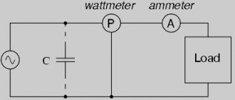
To carry out measurements in relation to active power in an electrical circuit, a special measuring device is used, which is called a wattmeter. Its readings are determined in accordance with the formula:
in the above formula, Uw and Iw are the vectors of the voltage applied to the load and the current flowing through it.
The nature of the active load and the phase connection diagram may be different, therefore, depending on the specific circumstances and the connection diagram of the wattmeters will be different.
For symmetrically loaded three-phase circuits, for the purpose of approximate measurement of the total active power, if high accuracy is not required, one wattmeter connected to only one of the phases is sufficient. Then, to obtain the active power value of the complete circuit, it remains to multiply the wattmeter readings by the number of phases:
For a four-wire circuit with a neutral wire, in order to accurately measure the active power, three wattmeters are needed, each of which is taken and then summed to obtain the total power of the circuit:
If there is no neutral wire in a three-phase circuit, then two wattmeters are sufficient to measure the total power, even if the load is asymmetrical.
In the absence of a neutral wire, the phase currents are related to each other in accordance with Kirchhoff's first law:
Then the sum of the readings of a pair of wattmeters will be equal to:
So, if you add up the readings of a pair of wattmeters, you will get the total active power in the three-phase circuit under study, and the readings of the wattmeters will depend on both the size of the load and its nature.
Looking at the vector diagram of currents and voltages in relation to a symmetrical load, we can come to the conclusion that the wattmeter readings are determined by the following formulas:
Having analyzed these expressions, we can understand that with a purely active load, when φ = 0, the readings of two wattmeters will be equal to each other, that is, W1 = W2.
With an active-inductive load, when 0 ≤ φ ≤ 90°, the readings of wattmeter 1 will be less than those of wattmeter 2, that is, W1 60°, the readings of wattmeter 1 will be negative, that is, W1
With an active-capacitive load, when 0 ≥ φ≥ -90°, the readings of wattmeter 2 will be less than wattmeter 1, that is, W1 > W2. At φ
Source
How to find out your scheme
To correctly determine and calculate power, knowledge of several factors is required:
- Number of power phases;
- Method of connecting consumers.
For a single-phase connection, two wires are used:
- Phase wire;
- Neutral wire.
A three-phase network is characterized by the presence of three or four conductors (connection with a grounded neutral). In this case, two different switching schemes are used:
- "Triangle". Each load is connected to two adjacent ones. The voltage of each phase is supplied to the consumer connection points.
- "Star". All three consumers are connected at one point. The power phases are connected to the second ends. This is an isolated neutral circuit. In a circuit with a grounded neutral, the consumer connection point is connected to the neutral conductor.
Three-phase or single-phase connection
Depending on what type of connection is used, the power consumption is determined differently.
In a single-phase network, the energy consumed is calculated using the simplest formula:
where cosϕ is the power factor characterizing the phase shift between current and voltage in a reactive load.
The power of a 3-phase network is the sum of consumption for each phase separately. The power formula for 3-phase current is as follows:
Ptotal=Uа∙Iа∙cosϕа+ Ub∙Ib∙cosϕb+ Uc∙Ic∙cosϕc,
where U, I, cosϕ are voltage, current and power factor in each phase, respectively.
For your information. It can be seen that in the general case, a three-phase connection requires a larger number of metering devices.
Sometimes you can calculate energy consumption using a simplified version. With symmetrical consumption, for example, when connecting an asynchronous motor, the consumption currents are the same, and the formula takes the following form:
Where:
- Uph, Iph – phase voltage and current;
- Ul, Il – linear voltage and current.
Star connection of consumers
In the general case of an asymmetric load, the active power of a three-phase receiver is equal to the sum of the active powers of the individual phases P = Pa + Pb + Pc, where Pa = Ua Ia cos φa; Pb = Ub Ib cos φb; Pc = Uc Ic cos φc; Ua, Ub, Uc; Ia, Ib, Ic – phase voltages and currents; φa, φb, φc – phase shift angles between voltage and current.
Reactive power is accordingly equal to the algebraic sum of the reactive powers of individual phases Q = Qa + Qb + Qc, where Qa = Ua Ia sin φa; Qb = Ub Ib sin φb; Qc = Uc Ic sin φc.
Total power of individual phases Sa = Ua Ia; Sb = Ub Ib; Sc = Uc Ic. Total power of a three-phase receiver.
With a symmetrical voltage system (Ua = Ub = Uc = UФ) and a symmetrical load (Ia = Ib = Ic = IФ; φa = φb = φc = φ), the phase powers are equal to Pa = Pb = Pc = PF = UФ IФ cos φ; Qa = Qb = Qc = QФ = UФ IФ sin φ.
Active power of a symmetrical three-phase receiver
P = 3 PF = 3 UФ IФ cos φ.
Reactive power is expressed similarly
Q = 3 QФ = 3 UФ IФ sin φ.
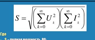
Full power
S = 3 SF = 3 UФ IФ.
It follows that in a three-phase circuit with a symmetrical voltage system and symmetrical load, it is enough to measure the power of one phase and triple the result.
Characteristics of a three-phase system
A three-phase power supply system is characterized by several voltage and current values. It all depends on between which points of the circuit the measurements are made:
- between the phase wire and the neutral – phase voltage Uph;
- between individual phases – linear Ul.
The relationship between these parameters:
With symmetrical load distribution, the currents in all wires are equal. In a four-wire circuit (with a grounded zero), there is no current in the neutral conductor, so even if the zero is broken, the network continues to function normally.
In the case where the energy consumption differs between phases, some current flows in the neutral wire. A complete break in the neutral conductor causes a phase imbalance, so the voltage on the wires can change in the range from zero to linear.
Example of calculating power indicators
The simplest example is the calculation of energy consumption by a symmetrical load. How much electricity will a three-phase asynchronous motor consume, connected to a network with a linear voltage of 380 V, and consuming a current of 10 A in each phase? Power factor cosϕ=0.76. Then the power consumption is:
More complex calculation of a household network:
- Phase voltage – 220 V;
- Line consumption – 10 A, 5 A, 2 A;
- The first two phases are connected to an active load (electric stove, kettle);
- The third is loaded with fluorescent lamps with cosϕ=0.5.
Ptotal=Uа∙Iа∙cosϕа+ Ub∙Ib∙cosϕb+ Uc∙Ic∙cosϕc=220∙10+220∙5+220∙2∙0.5=3520 VA.
Using an online calculation calculator, you can get rid of most errors and reduce calculation time. You just need to enter the data correctly according to the current parameters
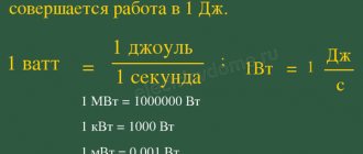
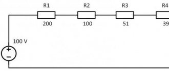
Formula for calculating the power of electric current
According to Ohm's law, current (I) is proportional to voltage (U) and inversely proportional to resistance (R), and power (P) is calculated as the product of voltage and current. Based on this, the current in the network section is calculated: I = P/U.
In real conditions, one more component is added to the formula and the formula for a single-phase network takes the form:
I = P/(U*cos φ),
and for a three-phase network: I = P/(1.73*U*cos φ),
where U for a three-phase network is assumed to be 380 V, cos φ is the power factor, reflecting the ratio of the active and reactive components of the load resistance.
Types of terminals for connecting wires: tips for choosing
RCD connection diagram: instructions, methods, errors
For modern power supplies, the reactive component is insignificant; the value of cos φ can be taken equal to 0.95. The exception is powerful transformers (for example, welding machines) and electric motors; they have high inductive reactance. In networks where it is planned to connect such devices, the maximum current should be calculated using a cos φ coefficient of 0.8, or the current should be calculated using the standard method, and then a multiplying factor of 0.95/0.8 = 1.19 should be applied.
Substituting the effective voltage values of 220 V/380 V and a power factor of 0.95, we obtain I = P/209 for a single-phase network and I = P/624 for a three-phase network, that is, in a three-phase network with the same load, the current is three times less. There is no paradox here, since three-phase wiring provides three phase wires, and with a uniform load on each phase it is divided into three. Since the voltage between each phase and working neutral wires is 220 V, the formula can be rewritten in another form, so it is more clear: I = P/(3*220*cos φ).
What is an RCD in electrical engineering: types, principle of operation
Connecting a two-key switch: diagrams, tips, instructions
Measuring power with a wattmeter
The power consumption of three-phase current is measured using wattmeters. This can be a special wattmeter for a 3-phase network, or a single-phase one connected according to a specific circuit. Modern electricity metering devices are often made using digital circuitry. Such designs are characterized by high measurement accuracy and greater capabilities for operating with input and output data.
Measurement options:
- Star connection with neutral conductor and symmetrical load - the measuring device is connected to one of the lines, the readings taken are multiplied by three.
- Asymmetrical current consumption in a star connection - three wattmeters in the circuit of each phase. The wattmeter readings are summed up;
- Any load and delta connection - two wattmeters connected in a circuit of any two loads. The wattmeter readings are also summed up.
In practice, they always try to make the load symmetrical. This, firstly, improves network parameters, and secondly, simplifies the accounting of electrical energy.
Three-phase circuit power
2015-02-27 16577
The active power of a three-phase circuit is equal to the sum of the active powers consumed by each load phase:
With a symmetrical load, the power consumed by each load phase is equal. In this case, , and the power consumed by each phase is defined as: .
where j is the shift angle between phase voltage and current.
Figure 4.11 — Vector diagram for an asymmetric load connected by a triangle
The reactive power of a three-phase circuit is equal to the sum of the reactive powers of the individual phases:
With a symmetrical load, the reactive powers of the individual phases are equal and the reactive power of a three-phase circuit, the reactive power of one phase: .
Three-phase circuit power with unbalanced load
LECTURE 9
Three-wire circuit (continued)
Connecting the receiver phases with a triangle
One of the main ways to noticeably change the power when the load is off is to switch the connection between the source and receiver from star to delta and vice versa.
When the beginning of one phase is connected to the end of another to form a closed circuit, a delta connection is obtained.
The receiver phases are connected by a triangle, i.e. three phases of the receiver are connected between the linear wires in Fig. 1.
The phase voltages of the receiver are equal to the corresponding line voltages of the power source:
those.
phase currents:
Positive direction of phase voltages
, and coincides with the positive direction of the phase currents.
When connecting a receiver with a triangle, a closed circuit is obtained, therefore:
Phase voltages are defined as linear generators:
; ;
Determination of phase and line currents
Currents in phases are determined by Ohm's law:
.
Linear currents are determined from phase currents according to Kirchhoff’s first law:
Linear currents are equal to the vector difference of phase currents of those phases that are connected to a given linear wire.
Regardless of the nature of the load, the sum of the line currents is always equal to 0.
When one of the phases changes, the operating mode of the other phases remains unchanged, because the generator line voltage remains constant. The delta connection is used for unbalanced loads.