POWER DELIVERED IN THE EXTERNAL CIRCUIT
. (2)
From formula (2) it is clear that during a short circuit (R0) and at R, this power is zero. For all other finite values of R, the power P1> 0. Consequently, the function P1 has a maximum. The value of R corresponding to the maximum power can be obtained by differentiating P1 with respect to R and equating the first derivative to zero:
. (3)
From formula (3), taking into account the fact that R and r are always positive, and E? 0, after simple algebraic transformations we get:
R= r. (4)
Consequently, the power released in the external circuit reaches its greatest value when the resistance of the external circuit is equal to the internal resistance of the current source.
In this case, the current strength in the circuit (5)
equal to half the short circuit current. In this case, the power released in the external circuit reaches its maximum value equal to
. (6)
When the source is closed to an external resistance, then current flows inside the source and at the same time a certain amount of heat is released at the internal resistance of the source. The power expended to release this heat is equal to
. (7)
Consequently, the total power released in the entire circuit is determined by the formula
= I2(R+r) = IE (8)
Physics
The efficiency of the current source (efficiency) is determined by the share of useful power from the total power of the current source:
η = P useful P full ⋅ 100%,
where P useful is the useful power of the current source (power released in the external circuit); P full - full power of the current source:
P total = P useful + P losses,
those. the total power released in the external circuit (P useful) and in the current source (P losses).
The efficiency of a current source (efficiency) is determined by the share of useful energy from the total energy generated by the current source:
η = E useful E complete ⋅ 100%,
where E useful is the useful energy of the current source (energy released in the external circuit); E total - total energy of the current source:
E total = E useful + E losses,
those. the total energy released in the external circuit (E useful) and in the current source (E losses).
The energy of the current source is related to the power of the current source by the following formulas:
- the energy released in the external circuit (useful energy) during time t is related to the useful power of the source P useful -
E useful = P useful t ;
- the energy released in the current source (loss energy) during time t is related to the loss power of the loss source P -
E losses = P losses t;
- the total energy generated by the current source during time t is related to the total power of the source Ptot -
E full = P full t.
The efficiency of the current source (efficiency) can be determined:
- the share of the resistance of the external circuit from the total resistance of the current source and load (external circuit) -
where R is the resistance of the circuit (load) to which the current source is connected; r is the internal resistance of the current source;
- the share of the potential difference at the terminals of the source from its electromotive force -
where U is the voltage at the terminals of the current source; ℰ — EMF of the current source.
At maximum power released in the external circuit, the efficiency of the current source is 50%:
since in this case the load resistance R is equal to the internal resistance r of the current source:
η * = RR + r ⋅ 100% = rr + r ⋅ 100% = r 2 r ⋅ 100% = 50%.
Example 16. When a current source with an efficiency of 75% is connected to a certain circuit, a power equal to 20 W is released on it. Find the amount of heat released in the current source in 10 minutes.
Solution . Let us analyze the condition of the problem.
The power released in the external circuit is useful:
P useful = 20 W,
where P useful is the useful power of the current source.
The amount of heat that is released in the current source is related to the power loss:
Q losses = P losses t,
where P losses is power loss; t is the operating time of the current source.
The source efficiency relates the useful and total power:
η = P useful P full ⋅ 100%,
where P total is the total power of the current source.
The useful power and power losses add up to the total power of the current source:
P total = P useful + P losses.
The written equations form a system of equations:
η = P useful P total ⋅ 100%, Q losses = P losses t, P total = P useful + P losses. >
To find the desired value - the amount of heat released in the source of losses Q - it is necessary to determine the power of losses P losses. Let's substitute the third equation into the first:
η = P useful P useful + P losses ⋅ 100%
and express P losses:
P losses = 100% − η η P useful.
Let's substitute the resulting formula into the expression for Q losses:
Q losses = 100% − η η P useful t .
Q losses = 100% − 75% 75% ⋅ 20 ⋅ 10 ⋅ 60 = 4.0 ⋅ 10 3 J = 4.0 kJ.
For the time specified in the problem statement, 4.0 kJ of heat will be released in the source.
Source
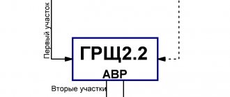
IT power and internal resistance
Defining and applying hand and gimlet rules
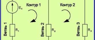
You can assemble a series circuit that includes a galvanic two-terminal network and a load resistance. A two-terminal network, having an internal impedance r and an emf - E, supplies current I to an external load R. The task of the circuit is to supply electricity to an active load that performs useful work. A light bulb or a heater can be used as a load.
A simple scheme for studying the dependence of Puseful. from R
Considering this circuit, you can determine the dependence of useful power on the resistance value. First, find the R-equivalent of the entire chain.
It looks like this:
Req. = R + r.
The movement of electricity in a circuit is found by the formula:
I = E/(R + r).
In this case, P EMF at the output will be Pout. = E*I = E²/(R + r).
Next, you can find P, dissipated when the generator heats up due to internal resistance:
Pr = I² * r = E² * r/(R + r)².
At the next stage, the power taken by the load is determined:
PR = I² * R = E² * R/(R + r)².
The total P at the output of the two-terminal network will be equal to the sum:
Rych. = Pr + PR.
This means that energy losses initially occur when dissipated by the impedance (internal resistance) of a two-terminal network.
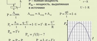
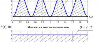
Next, to see at what load value the maximum value of useful power Ruseful is achieved, a graph is drawn.
When examining it, it is clear that the highest power value is at the point where R and r are equal. This is the point where the generator and load resistances are matched.
Attention! When R > r, the current generated in the circuit is small to transfer energy to the load at a sufficient speed. At R
The most obvious example of matching can be seen in radio engineering when matching the output impedance of a ULF (low frequency amplifier) and audio speakers. At the amplifier output, the resistance ranges from 4 to 8 ohms, while the Rin of the speaker is 8 ohms. The device allows you to connect to its output stage either one 8 Ohm speaker or two 4 Ohm speakers in parallel. In both cases, the ULF will operate in the specified mode, without loss of power.
In the process of developing certain real current sources, they use its representation in the form of an equivalent block. It consists of two components with which work is carried out: this is the ideal source and its impedance.
Theoretical introduction. Study of the dependence of the power and efficiency of the current source on the load size
Studying the dependence of the power and efficiency of the current source on the load value.
Purpose of the work: experimental Study of the dependence of the useful, total power and efficiency of the current source on the load current.
Equipment: current source
To maintain conductivity in a direct current circuit, it is necessary that, in addition to Coulomb forces, some other non-electric forces, called external forces, act on the current carriers. They can be caused by chemical processes, diffusion of charge carriers in a heterogeneous medium or across the boundary of two dissimilar substances, electric (but not electrostatic) fields generated by time-varying magnetic fields, etc. Under the influence of the created field of external forces, electric charges move inside the current source against the forces of the electrostatic field, due to which a constant potential difference is maintained at the ends of the circuit and a constant electric current flows in the circuit.
Third-party forces can be characterized by the work they do on charges moving along the chain. A physical quantity determined by the ratio of the work done by external forces to move a charge along a circuit to the magnitude of this charge is called electromotive force (EMF)
, acting in a circuit or on its section.
Consequently, if the work of external forces to move a charge dq through
an electric circuit is equal to dA,
then
, by definition: . (1)
An electrical circuit usually consists of a current source, supply wires and a current consumer or load. The current in a closed circuit is determined by Ohm's law:
, (2)
where r
— internal resistance of the current source;
R
is the resistance of the external circuit, i.e. resistance of supply wires and load. As a rule, the resistance of the supply wires is small and is often neglected.
When current passes through a circuit, work is done. Since the work of Coulomb forces to move a charge along a closed circuit is zero (the electrostatic field is potential), then the work to move a charge dq
along a closed circuit will be determined only by the work of external forces and will be equal, as follows from (1),
.
(3) By dividing the work dA
for the time dt
,
we obtain the power developed by the current source: (
) Substituting
I
its value (2), we obtain for the total power released in the entire circuit the expression .
(5)
Only part of this power is released in the load:
, (6)
which we call useful power. The rest of the power is spent in the current source and turns out to be useless.
Ratio of useful power to total power P
, developed by the emf in the circuit, determines the coefficient of performance (efficiency) of the current source:
.
(7) From this formula it follows that the greater the load resistance R
compared to the source resistance r .
Therefore, they strive to make the resistance of the current source as small as possible.
The power developed by a given current source depends on the load resistance R
.
It is maximum during a short circuit ( R
®0, see formula 5):
, (8)
but in this case, all the power is released in the source itself and turns out to be completely useless. With increasing load resistance R
the total power decreases, tending to zero as
R
® ¥.
It is possible to obtain a ratio at which the useful power taken from a given current source will be the greatest. To do this, you need to differentiate expression (6) with respect to R
and equate the derivative to zero.
From here we find that RN
has a maximum at
R=r
(another solution R =
¥
corresponds to the minimum RN) .
Therefore, in order to select the greatest useful power from a given EMF, you need to take a load resistance equal to the resistance of the current source. The efficiency in this case, as follows from (7), is equal to 0.5.
Installation diagram and measurement method
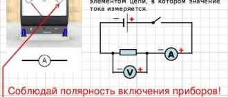
The unit is mounted in a metal casing. Its diagram is shown in Fig. 1.
| Rice. 1 |
1 – current source; 2 – power switch; U – voltmeter; mA – milliammeter; R – rheostat.
The method for determining EMF consists of measuring the current and voltage in the circuit at various values of load resistance. If R
1 and
R
2 are the load resistances, then these resistances, as follows from formula (2), correspond to the currents:
;
; Having solved this system of two equations with two unknowns and r
relatively and assuming U 1
=
I 1
R
1
and
U 2
=
I 2
R
2
,
we obtain a formula for determining the EMF :.
(9)
Your opinion is important to us! Was the published material useful? Yes | No
Source
Definition
Mathematically, the efficiency is defined as
η=AQ,{\displaystyle \eta ={\frac {A}{Q}},}
where A
is useful work (energy), and
Q
is the energy expended.
When efficiency is expressed as a percentage, this formula is sometimes written as
η=AQ×100%{\displaystyle \eta ={\frac {A}{Q}}\times 100\%}.
Here, multiplying by 100%{\displaystyle 100\%} does not have any meaningful meaning, since 100%=1{\displaystyle 100\%=1}. In this regard, the second option for writing the formula is less preferable (the same physical quantity can be expressed in different units, regardless of the formulas in which it is involved).
Due to the law of conservation of energy and as a result of irreparable energy losses, the efficiency of real systems is always less than one, that is, it is impossible to obtain more useful work or as much as the amount of energy expended.
Heat engine efficiency
- the ratio of the completed useful work of the engine to the energy received from the heater.
The efficiency of a heat engine can be calculated using the following formula η=Q1−Q2Q1{\displaystyle \eta ={\frac {Q_{1}-Q_{2}}{Q_{1}}}},
where Q1{\displaystyle Q_{ 1}} is the amount of heat received from the heater, Q2{\displaystyle Q_{2}} is the amount of heat given to the refrigerator. The highest efficiency among cyclic machines operating at given heater temperatures T
1 and refrigerator
T
2, have heat engines operating on the Carnot cycle;
this marginal efficiency is equal to ηk=T1−T2T1{\displaystyle \eta _{k}={\frac {T_{1}-T_{2}}{T_{1}}}}.
Types of DC power
Microcontroller: definition, tasks, varieties, application
Any power value is determined by the work that is done in a certain unit of time. Most often it becomes a second. It means a quantity that characterizes how quickly work is done. Regarding electrical power, this is the energy consumption per second.
The power characteristic of the current corresponds to the ratio of its work to time
Current work is the process of converting electricity into some other energy (mechanical, thermal or light). It is by power, which is designated by the letter “P” or “W,” that the performance of the electric current is assessed.
For your information! In general, a constant current does not have an active and reactive P. This type of network is characterized by only an instantaneous characteristic.
Instantaneous power
If we talk about alternating current networks, then the value in question in them, like electric current or voltage, regularly changes its values. This directly affects other parameters. With a constant flow of charges, everything remains unchanged. This is where the term “instantaneous power” comes from.
The forces in a regular current network remain unchanged and are equal to their instantaneous values taken at an arbitrary point in time. This characteristic can be calculated using instantaneous values. The formula for DC power in the circuit is suitable for this: P = I * U.
The value under consideration can be found from the product of electric current and voltage
If the network is passive and Ohm’s law is observed in it, then equality is true. In the case of connecting an EMF source, a different formula is needed: P = I * E, where E is the electromotive force.
Active power
Active power is the average value of instantaneous P over a period. With active P, current power is converted into energy of any type (mechanical, light or thermal). Such a transfer of electric current cannot be performed in the opposite direction. Active type is also measured in watts. 1 Watt is equal to 1 volt times 1 ampere.
The work is inextricably linked with the determination of power characteristics
For your information! On a domestic and even more so industrial scale, the unit of measurement watt is never used. For these purposes, indicators that are an order of magnitude higher are used: megawatts to kilowatts.
Reactive power
The reactive power characteristic determines the load that is created by electrical devices due to certain fluctuations in the energy of the electromagnetic field in sinusoidal current networks of variable frequency. It is equal to the product of the rms voltage and current values multiplied by the sine of the angle by which the phase shifts between them. The reactive parameter is inextricably linked with the full P and the active parameter.
All basic quantities can be found using Ohm's law
If we talk about the physical meaning of reactivity, then it represents a certain energy that is pumped from the source to the reactive elements of the receiver (capacitor, generator winding, inductor, etc.), and then returns back to the source during one oscillation period.
Full power
The total P of the electric current is the value corresponding to the product of the electric current and the voltage in the circuit. It is inextricably linked with active and reactive quantities and is determined by the following equation: where Sos = total power, and P and Q are its active and reactive characteristics, respectively.
Total power that can be represented as a glass of beer
To put it simply, active P exists wherever there is an active load. For example, in spiral heaters, wire resistance, etc. The reactive parameter is characteristic of the reactive load that is present in the inductive or capacitive elements.
Electrical circuit efficiency
The efficiency factor under consideration is primarily associated with physical quantities characterizing the speed of conversion or transmission of electricity. Among them, power, measured in watts, comes first. There are several formulas to determine it: P = U x I = U2/R = I2 x R.
Electrical circuits may have different voltages and charge amounts, and accordingly, the work performed is also different in each case. Very often there is a need to estimate the speed at which electricity is transmitted or converted. This speed represents the electrical power corresponding to the work done in a certain unit of time. In the form of a formula, this parameter will look like this: P=A/∆t. Therefore, work is displayed as the product of power and time: A=P∙∆t. The unit of work used is the joule (J).
To determine how efficient a device, machine, electrical circuit, or other similar system is in terms of power and operation, the efficiency factor is used. This value is defined as the ratio of usefully expended energy to the total amount of energy entering the system. Efficiency is denoted by the symbol &eta,, and is defined mathematically as the formula: &eta, = A/Q x 100% = [J]/[J] x 100% = [%], in which A is the work performed by the consumer, Q is the energy given by the source . In accordance with the law of conservation of energy, the efficiency value is always equal to or below unity. This means that useful work cannot exceed the amount of energy expended in doing it.
In this way, the power losses in any system or device are determined, as well as the degree of their usefulness. For example, in conductors, power losses occur when electrical current is partially converted into thermal energy. The amount of these losses depends on the resistance of the conductor; they are not part of the useful work.
There is a difference expressed by the formula ∆Q=AQ, which clearly shows the power loss. Here the relationship between the increase in power losses and the resistance of the conductor is very clearly visible. The most striking example is an incandescent lamp, the efficiency of which does not exceed 15%. The remaining 85% of the power is converted into thermal, that is, infrared radiation.
Heat engine
Efficiency formula
An engine in which the internal energy of the fuel that burns is converted into mechanical work.
Any heat engine consists of three main parts: the heater
,
working fluid
(gas, liquid, etc.) and
refrigerator
. The operation of the engine is based on a cyclic process (this is the process as a result of which the system returns to its original state).
Direct cycle heat engine
A common property of all cyclic (or circular) processes is that they cannot be carried out by bringing the working fluid into thermal contact with only one heat reservoir. You need at least two of them. A heat reservoir with a higher temperature is called a heater, and a heat reservoir with a lower temperature is called a refrigerator. Carrying out a circular process, the working fluid receives a certain amount of heat Q1 from the heater (expansion occurs) and transfers an amount of heat Q2 to the refrigerator when it returns to its original state and contracts. The total amount of heat Q=Q1-Q2 received by the working fluid per cycle is equal to the work performed by the working fluid in one cycle. Refrigerator reverse cycle
In the reverse cycle, expansion occurs at lower pressure and compression occurs at higher pressure. Therefore, the work of compression is greater than the work of expansion; the work is performed not by the working fluid, but by external forces. This work turns into heat. Thus, in a refrigeration machine, the working fluid takes a certain amount of heat Q1 from the refrigerator and transfers a larger amount of heat Q2 to the heater.
Carnot cycle
In heat engines, they strive to achieve the most complete conversion of thermal energy into mechanical energy. Maximum efficiency.
The figure shows the cycles used in a gasoline carburetor engine and a diesel engine. In both cases, the working fluid is a mixture of gasoline or diesel fuel vapor with air. The cycle of a carburetor internal combustion engine consists of two isochores (1–2, 3–4) and two adiabats (2–3, 4–1). A diesel internal combustion engine operates on a cycle consisting of two adiabats (1–2, 3–4), one isobar (2–3) and one isochore (4–1). The actual efficiency of a carburetor engine is about 30%, and that of a diesel engine is about 40%.
The French physicist S. Carnot developed the operation of an ideal heat engine. The working part of a Carnot engine can be imagined as a piston in a gas-filled cylinder. Since the Carnot engine is a purely theoretical machine, that is, ideal
, friction forces between the piston and cylinder and heat losses are considered equal to zero.
Mechanical work is maximum if the working fluid performs a cycle consisting of two isotherms and two adiabats. This cycle is called the Carnot cycle
.
section 1-2: the gas receives an amount of heat Q1 from the heater and expands isothermally at a temperature T1 section 2-3: the gas expands adiabatically, the temperature drops to the temperature of the refrigerator T2 section 3-4: the gas is exothermically compressed, while it gives up the amount of heat Q2 to the refrigerator section 4- 1: the gas is compressed adiabatically until its temperature rises to T1. The work performed by the working fluid is the area of the resulting figure 1234.
Such an engine functions as follows:
1. First, the cylinder comes into contact with a hot reservoir and the ideal gas expands at a constant temperature. In this phase, the gas receives a certain amount of heat from the hot reservoir.2. The cylinder is then surrounded by perfect thermal insulation, due to which the amount of heat available in the gas is conserved and the gas continues to expand until its temperature drops to the temperature of the cold heat reservoir.3. In the third phase, the thermal insulation is removed, and the gas in the cylinder, being in contact with the cold reservoir, is compressed, thereby transferring some of the heat to the cold reservoir.4. When the compression reaches a certain point, the cylinder is again surrounded by thermal insulation and the gas is compressed by raising the piston until its temperature is equal to that of the hot reservoir. After this, the thermal insulation is removed and the cycle is repeated again from the first phase.
The efficiency of the Carnot cycle does not depend on the type of working fluid for the refrigeration machine
In real heat engines
it is impossible to create conditions under which their operating cycle would be a Carnot cycle. Since the processes in them occur faster than is necessary for an isothermal process, and at the same time not so fast as to be adiabatic.
Study of power and efficiency of current generator
Maximum useful Pmax and maximum efficiencymax are incompatible concepts. Maximum source efficiency cannot be achieved at maximum power. This is due to the fact that P, given by a two-terminal network, will reach its maximum value only if the load resistance and the internal impedance of the IT are matched:
In this case, the source efficiency will be:
η = R/ R+r = r/ r+r = 1/2, which is only 50%.
To match the two-terminal network and the load, electronic circuits or matching blocks are used in order to achieve maximum power take-off from the source.
Efficiency | Physics
Using this or that mechanism, we perform work that always exceeds that which is necessary to achieve the goal. In accordance with this, a distinction is made between the complete or expended work As and the useful work Ap. If, for example, our goal is to lift a load of mass m to a height h, then useful work is that which is due only to overcoming the force of gravity acting on the load. With a uniform lifting of the load, when the force we apply is equal to the gravitational force of the load, this work can be found as follows:
Ap = Fth = mgh. (24.1)
If we use a block or some other mechanism to lift a load, then, in addition to the gravity of the load, we also have to overcome the gravity of the parts of the mechanism, as well as the frictional force acting in the mechanism. For example, using a movable block, we will be forced to do additional work to lift the block itself with a cable and to overcome the friction force in the axis of the block. In addition, while we win in strength, we always lose along the way (this will be discussed in more detail below), which also affects work. All this leads to the fact that the work we expended turns out to be more useful:
Az > Ap
Useful work is always only a small part of the total work done by a person using a machine.
A physical quantity that shows what proportion of useful work is the total work expended is called the efficiency of the mechanism.
The abbreviation for efficiency is efficiency.
To find the efficiency of a mechanism, it is necessary to divide the useful work by that which was expended when using this mechanism.
Efficiency is often expressed as a percentage and denoted by the Greek letter η (read “eta”):
η =* 100% (24.2)
Since the numerator Ap in this formula is always less than the denominator Az, the efficiency is always less than 1 (or 100%).
When designing mechanisms, they strive to increase their efficiency. To do this, reduce friction in the axes of the mechanisms and their mass. In cases where friction is negligible and the mechanisms used have a mass that is negligible compared to the mass of the load being lifted, the efficiency coefficient is only slightly less than 1. In this case, the work expended can be considered approximately equal to the useful work:
Az ≈ Ap (24.3)
It should be remembered that winning at work cannot be achieved using a simple mechanism.
Since each of the works in equality (24.3) can be expressed as the product of the corresponding force and the distance traveled, this equality can be rewritten as follows:
F1s1 ≈ F2s2 (24.4)
It follows that,
winning with the help of a mechanism in force, we lose the same number of times along the way, and vice versa.
This law is called the “golden rule” of mechanics. Its author is the ancient Greek scientist Heron of Alexandria, who lived in the 1st century. n. e.
The “golden rule” of mechanics is an approximate law, since it does not take into account the work of overcoming friction and gravity of the parts of the devices used. Nevertheless, it can be very useful in analyzing the operation of any simple mechanism.
So, for example, thanks to this rule, we can immediately say that the worker shown in Figure 47, with a double gain in force to lift a load by 10 cm, will have to lower the opposite end of the lever by 20 cm. The same will happen in the case shown in Figure 58. When the hand of the person holding the rope drops 20 cm, the load attached to the movable block rises only 10 cm.
1. Why does the work expended when using mechanisms always turn out to be more useful work? 2. What is called the efficiency of the mechanism? 3. Can the efficiency of the mechanism be equal to 1 (or 100%)? Why? 4. How to increase efficiency? 5. What is the “golden rule” of mechanics? Who is its author? 6. Give examples of the manifestation of the “golden rule” of mechanics when using various simple mechanisms.
Study of power dependence of current source efficiency
LABORATORY WORK No. 3.7.
STUDY OF USEFUL POWER AND EFFICIENCY OF CURRENT SOURCES
Last name I.O. _____________ Group ______ Date ______
The purpose of this work is to experimentally test the theoretical conclusions about the dependence of the useful power and efficiency of the current source on the load resistance.
An electrical circuit consists of a current source, supply wires and a load or current consumer. Each of these circuit elements has resistance.
The resistance of the lead wires is usually very small, so it can be neglected. In each section of the circuit, the energy of the current source will be consumed. The question of the appropriate use of electrical energy is of very important practical importance.
The total power P allocated in the circuit will be the sum of the powers allocated in the external and internal parts of the circuit: P = I 2 R + I 2 r = I 2 (R + r)
.
Since I(R + r) = ε
, then
Р =I·ε,
where R is the external resistance; r – internal resistance; ε – EMF of the current source.
Thus, the total power released in the circuit is expressed by the product of the current and the emf of the element. This power is released due to any third-party energy sources; such energy sources can be, for example, chemical processes occurring in the element.
Let's consider how the power released in the circuit depends on the external resistance R to which the element is closed. Let us assume that an element of a given EMF and a given internal resistance r is closed by an external resistance R; Let us determine the dependence on R of the total power P allocated in the circuit, the power Ra allocated in the external part of the circuit and the efficiency.
The current strength I in the circuit is expressed according to Ohm's law by the relation
The total power released in the circuit will be equal to
As R increases, the power decreases, tending asymptotically to zero as R increases indefinitely.
The power released in the external part of the circuit is equal to
This shows that the useful power Ra is zero in two cases - at R = 0 and R = ∞.
Investigating the function Pa = f(R)
to the extremum, we find that Ra reaches a maximum at R = r, then
To make sure that the maximum power Pa is obtained at R = r, let us take the derivative of Ra with respect to the external resistance
According to the maximum condition, the first derivative
r 2 = R 2 R = r
. You can make sure that under this condition we will obtain a maximum and not a minimum for Ra by determining the sign of the second derivative
.
The efficiency factor (efficiency) η of an EMF source is the ratio of the power Ra released in the external circuit to the total power P developed by the EMF source.
In essence, the efficiency of an EMF source indicates what proportion of the work of external forces is converted into electrical energy and transferred to the external circuit.
Expressing power in terms of current I, the potential difference in the external circuit U and the magnitude of the electromotive force ε, we obtain
That is, the efficiency of the EMF source is equal to the ratio of the voltage in the external circuit to the EMF. Under the conditions of applicability of Ohm's law, one can further replace U = IR; ε = I(R + r
), Then
Consequently, in the case when all the energy is spent on Lenz-Joule heat, the efficiency of the EMF source is equal to the ratio of the external resistance to the total resistance of the circuit.
Electric current and load
Ohm's Law comes into play. As I already wrote, this is the most significant law in all electronics. What exactly is a light bulb? This is tungsten wire in a glass flask with a vacuum. Tungsten is a metal, therefore it can conduct electric current through itself. But the funny thing is that at a certain voltage it becomes hot and begins to glow. That is, giving energy into space in the form of heat and radiation.
In a cold state, a tungsten filament has less resistance than in a hot state, more than ten times. Therefore, a light bulb is simply like a resistance for an electrical circuit. In this article, I took a light bulb to visually show the load. Load – from the word “load”. The power supply doesn't like being forced to supply electricity. He likes to work without load 
Now let's imagine all this from a hydraulic and mechanical point of view.
We have a pipe through which water flows rapidly. A turntable, like a water wheel, is attached to the pipe. The blades of the turntable rotate the shaft.
I drew the drawing according to all the dogmas of drawing: the main view, and on the right is its section.
If nothing clings to the shaft, then a stream of water runs violently through the pipe and spins the wheel, which in turn spins the shaft. This mode can be called the idle mode of operation of the water wheel, that is, the mode without load.
But what happens if we start using the rotation of the shaft for our benefit? For example, let's connect the shaft of a water wheel with the shaft of a mini-mill using a coupling?
I think many of my readers will immediately guess that the water wheel will begin to slow down, since we made it work. Our shaft will no longer be able to spin at idle speed. The speed will be less. That is, in our case we have a load on the shaft. What will happen to the flow of water in the pipe? It will slow down, since the shaft blades will not allow the water to flow calmly through the pipe. Therefore, the total water flow in the pipe will be less than BEFORE the shaft is idling.
What if you load the shaft so that it lifts a freight elevator?
I think the whole structure will immediately become a stake. That is, a large load will become unbearable for the shaft. And if we made the blades of the turntable so that they completely covered the diameter of the pipe, then the flow of liquid would stop altogether.
Let's take another example for understanding. Still the same drawing:
Let's assume that we attached emery to the shaft and removed the electric motor from this structure. So we decided to polish something.
So what do we get as a result? If we put little pressure on the grinding wheel, then the wheel will begin to slow down and will spin at a different speed. If we press harder on the circle, the speed of the shaft will drop even more. If the power of our shaft is rather weak, we can achieve a situation where, with strong pressure on the circle, we can stop the shaft altogether. Then nothing will be sharpened...
Let's go back to the mini mill again
What happens if the water flow in the pipe is increased several times? The mill will spin so that it will fucking break! What if the water flow in the pipe is very weak? Of course, the mill will grind one or two grains per hour. Although, again, with a large flow of water we can easily raise the elevator.
Do you understand what I'm getting at? Everything is connected to each other! Pipe pressure, fluid flow rate and load... They are all connected together.
What is a current source
This is a device or element, in the general sense, a two-terminal network in which the current passing through it does not depend on the voltage at the poles. Main characteristics of the current source (IT):
- size;
- internal conductivity (impedance).
The internal resistance of such a two-terminal network is very small. At an ideal source (IIT) it approaches zero.
Electron motion generators can be either independent or dependent.
The first are an ideal two-terminal network, with two terminals. In them, the current moving from one terminal to another does not depend on the shape and magnitude of the potential difference across the terminals. Its changes occur according to their own laws.
The second type of IT is an ideal two-terminal network, with two terminals, in which the movement of charges from one terminal to another depends on the shape and magnitude of the voltage at these terminals.
There is managed dependent IT. It is an ideal two-terminal network, having 2 input terminals and 2 output terminals. Its peculiarity is that the output current value at the output depends on its value at the input. In such IT there is an increase in power. By changing the zero power value at its input, the amount of power at the output terminals is controlled.
Information. The energy producer can be controlled by voltage (ITUN) or current (ITUT). Some are used for field-effect triodes and vacuum tubes, while others are used for bipolar transistors.
In reality, current generators have certain voltage limitations. They are far from ideal IT and create the movement of electricity in a voltage range where their upper limit depends on Upit IT. Therefore, a real current source has significant load limits.
Other similar indicators
Not all indicators characterizing the efficiency of energy processes correspond to the above description. Even if they are traditionally or erroneously called "efficiency", they can have other properties, in particular exceeding 100%.
Boiler efficiency
Main article: Boiler heat balance
The efficiency of boilers is not traditionally calculated based on the lower calorific value; it is assumed that the moisture of the combustion products leaves the boiler in the form of superheated steam. In condensing boilers, this moisture is condensed, and the heat of condensation is usefully used. When calculating efficiency based on the lower calorific value, it may end up being greater than one. In this case, it would be more correct to calculate it by the higher calorific value, taking into account the heat of condensation of steam; however, the performance of such a boiler is difficult to compare with data on other installations.