Fuses are designed to protect electrical circuits from short circuits and overloads. At one time, these devices were used everywhere in various electrical installations, including in the residential sector, but with the advent of automatic switches, they gradually disappeared from our apartments.
Despite the fact that classic “plugs” can rarely be found in home electrical panels, this does not mean that fuses have become some kind of anachronism. They continue to be widely used in switchgear, industrial installations, and electronics, largely due to their reliability, response speed, simplicity of design and low cost.
Moreover, sometimes fuses are preferable as a protective device than circuit breakers, for example, manufacturers recommend using high-speed fuses to protect semiconductor equipment such as frequency converters, soft starters, etc. since circuit breakers cannot always provide the required speed, and this can be critical for power diodes, transistors, and thyristors.
A fuse is called a fuse because it is based on a fuse link, which, when a current exceeding a specified value passes through it, is heated to a temperature at which it melts, thereby breaking the circuit. These processes are based on the Joule-Lenz law, according to which, when an electric current flows, heat is released on the conductor.
This leads to the main disadvantage of such fuses - after tripping they must be changed every time.
It is true that it is worth noting that there is a type of self-resetting fuses made of polymer materials with a positive temperature coefficient of resistance. The principle of their operation is based on the fact that when the threshold current value is exceeded, their resistance sharply increases, which leads to a break in the electrical circuit. After eliminating the cause of the trigger, its resistance is restored and the circuit is closed again.
Fuse types
Depending on their purpose, fuses are manufactured in various types.
Low current . They are used in circuits designed for low current consumption - up to 6A. This is perhaps the most common type of fuses that are often found in household electrical appliances. There are different standard sizes, indicating the outer diameter x length (3×15, 4×15, 5×20, 6×32, 7×15, 10×30).
This group also includes thermal fuses.
Fork . This type of fuses are widely used in cars. They differ in the size and shape of the case - Mini - H=16 mm, Standard - H=19 mm, Maxi - H= 34mm. Depending on the rated current value, the housings have different color markings.
Cork . They are used both in industrial equipment and in the residential sector. Designed for rated current up to 63A. In their design they are almost identical to low-current ones, only they have a ceramic body rather than glass. The base for such fuses is either NEOZED type threaded sockets or MINIZED type disconnectors with a drawer tray.
Knife . They are used in power circuits of electrical installations up to 1000V. Rated for current up to 1250A. The body of blade fuses is filled with a special filler to extinguish the electric arc, which is usually quartz sand. Depending on the design, they may have a visual indicator of operation and a mechanism for remote signaling of operation.
Quartz and Gas-generating . Used in high-voltage networks.
Advantages and disadvantages
The advantages of fuses include their relatively low cost.
The main disadvantage of a fuse is that it takes a relatively long time to operate compared to automatic fuses. During the time a fuse blows in high-voltage networks, equipment may fail. In addition, a fuse is a disposable element, that is, once it burns out, it cannot be used for further use, while automatic fuses can serve for quite a long time, since the principle of their operation is based on opening the circuit without damaging the structure of the fuse itself.
Fuse selection
When choosing fuses, you should first of all pay attention to such parameters as:
- The rated voltage of the fuse must correspond to the operating voltage of the network, while the actual voltage in the network should not exceed the rated voltage of the fuse by more than 10%.
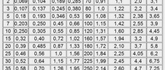
- The rated current of the fuse-link must be greater than the maximum continuous load current - In.v. >In.max, in this case it is necessary to take into account the nature of the load. For example, when protecting an electric motor, it is necessary to take into account short-term overloads caused by starting currents - In.v. > Istart.motor/k - where k is a coefficient that takes into account the ratio of the starting current to the rated current. According to the PUE clause 5.3.56, for engines with easy starting conditions k is taken equal to 2.5, for engines with heavy starting (long acceleration times, frequent starts, etc.) k should be equal to 2.0-1.6.
- The rated shutdown current is taken based on the calculated maximum short-circuit current of the line and must be equal to it or greater than Inom.off ≥ Imax.short.
- Response time characteristics , which again depend on the nature of the protected load. There are four types of fuses available:
- ultra-fast - usually used to protect semiconductor devices and microcircuits.
- Quick acting - main applications in control and signaling circuits.
- Standard fuses - have a wide range of applications.
- with a time delay or slow acting (Time-lag, Slow acting) - designed to protect electric motor circuits with high starting currents.
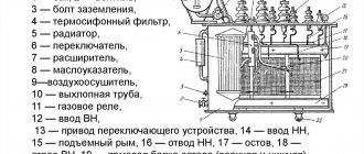
Purpose, operating principle and fuse design
To speed up the melting of the inserts during overloads, tin balls are soldered onto the wires. With overload currents, the ball melts and dissolves part of the metal on which it is soldered. The insert burns out where the ball is soldered.
Fuse parameters
The fuse operates in two sharply different modes: under normal conditions and under overload and short-circuit conditions. In the first case, overheating of the insert has the character of a steady-state process in which all the heat generated in it is released into the environment. In this case, in addition to the insert, all other parts of the fuse are heated to a steady temperature. This temperature should not exceed permissible values. The current for which the fuse-link is designed for long-term operation is called the rated current of the fuse-link Inom.
It may be different from the rated current of the fuse itself.
Typically, fuses with different rated currents can be inserted into the same fuse. Fuse rated current
, indicated on it, is equal to the highest of the currents of the fuse links intended for this fuse design.
The protective properties of the fuse during overloads are standardized. For normal speed fuses, the conditional non-melting current
- current, when flowing for a certain time, the fuse-link should not burn out,
conditional melting current
- current, when flowing within a certain time, the fuse-link should burn out.
For example, for a fuse with fuse links for rated currents of 63 -100 A, the fuse links should not burn out when a current of 1.3 I
nom flows for one hour, and with a current of 1.6
I
nom they should burn out in up to one hour.
Let's consider the heating of the insert under prolonged load.
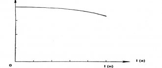
The main characteristic of a fuse is the time-current characteristic
, which is the dependence of the melting time of the insert on the flowing current
t
=f(
i
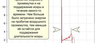
). For perfect protection, it is desirable that the time-current characteristic of the fuse (curve 1 in Fig. 6.3) at all points is slightly lower than the characteristic of the protected circuit or object (curve 2 in Fig. 6.3). However, the actual characteristics of the fuse (curve
3) intersects curve 2. Let us explain this. If the fuse characteristic corresponds to curve 1, then it will blow due to aging or when starting
Rice. 6.3. Coordination of characteristics of the fuse and the protected object
engine. The circuit will turn off in the absence of unacceptable overloads. Therefore, the melting current of the insert is selected greater than the rated load current. In this case, curves 2 and 3 intersect. In the area of high overloads (area B), the fuse protects the object. In area A, the fuse does not protect the object. For small overloads (1.5 – 2) I
Nominal heating of the fuse proceeds slowly. Most of the heat is given off to the environment,
The current at which the fuse-link burns out when it reaches a steady temperature is called the boundary current I
nogr.
In order for the fuse not to trip at the rated current I
nom, it is necessary
I
nogr >
I
nom.
On the other hand, for better protection, the value of I
nogp should be as close as possible to the nominal value.
To reduce the melting temperature of the insert, low-melting metals and alloys (copper, silver, zinc, lead, aluminum) are used during its manufacture.
Let us consider the heating of the insert during a short circuit.
If the current passing through the insert is 3 - 4 times greater than I
nom, then practically the heating process proceeds adiabatically, i.e. all the heat generated by the insert goes to heating it.
Time for heating the insert to the melting temperature
,
where A' is a constant determined by the properties of the material; q
— cross-section of the insert;
j
k is the insertion current density.
As part of the fusible link changes from solid to liquid, its resistivity will increase sharply (tens of times). Time to transition from solid to liquid
,
where is the resistivity of the insert material at the melting temperature; — specific resistance of the insert material in the liquid state; y is the density of the insert material; L
- latent heat of fusion of the material
inserts.
The main parameter of a fuse during a short circuit is the maximum shutdown current
- the current that it can turn off at a returning voltage equal to the highest operating voltage.
The lifetime of the arc depends on the design of the fuse. Total circuit fuse disconnection time
t
pr =
t
pl
+ t
cross +
t
arc
For a fuse with an insert in the air
,
where coefficient n
=3 takes into account premature destruction of the insert, and k0 = 1.2 -1.3 takes into account the duration of arc burning.
In fuses with a filler (closed type), destruction of the insert before its complete melting is less likely. Circuit break time by fuse
,
The coefficient cd = 1.7 -2 takes into account the duration of the arc.
Melting of an insert of variable cross-section occurs in isthmuses with the smallest cross-section. The heating process proceeds so quickly that the heat almost does not have time to be transferred to areas of increased cross-section. The presence of isthmuses of reduced cross-section makes it possible to sharply reduce the time from the onset of a short circuit to the appearance of an arc. The arc extinguishing process begins until the short-circuit current reaches a steady-state or even amplitude value. The arc is formed after time t
1 after the onset of a short circuit, when the current in the circuit is significantly less than the steady-state value
I
k set.
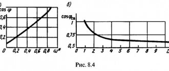
Arc extinguishing means can extinguish the arc in milliseconds. In this case, the current-limiting effect shown in Fig. When disconnecting a damaged current-limiting circuit, it is easier to extinguish the arc, since it is not the steady-state short-circuit current that is switched off, but the current determined by the melting time of the insert.
Rice. 6.4. Switching off DC and AC current using a current-limiting fuse
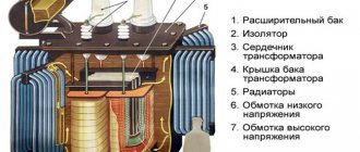
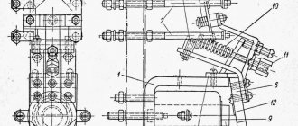
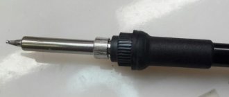
Fuse design
c) Fuse device. Wide application of fuses in
various areas of the national economy and in everyday life has led to a variety of their designs. However, despite this, they all have the following basic elements: a housing or load-bearing part, a fuse-link, a contact connecting device, an arc-extinguishing device or an arc-extinguishing medium.
⇐ Previous23Next ⇒
Recommended pages:
Fuse markings
The standard fuse marking consists of two letters.
The first letter indicates the protection range:
a - partial range (protection only against short-circuit currents)
g - full range (protection against short circuit currents and overloads)
The second letter indicates the type of equipment being protected:
G - universal for protecting various types of equipment: cables, electric motors, transformers.
L - for protecting cables and distribution devices.
B - to protect mining equipment. They have increased explosion safety requirements.
F - protection of low-current circuits
M - for circuits of electric motors and disconnecting devices.
R - for protecting semiconductor devices.
S - high-speed in case of short circuit and average response time in case of overload.
Tr - for protecting transformers.
On high-speed fuses, the diode sign can also be indicated as a graphic designation -
Time-delay fuses often display a stylized snail symbol -
The table below shows the main classes of fuses and their scope.
| Triggering characteristics | Application area |
| gB | Fuses that operate over the entire load range to protect cables and power lines in mining applications |
| gG | Fuses operating over the entire load range, for general use, mainly protecting cables and lines |
| gR | Fuses that operate over the entire load range to protect semiconductor elements |
| gS | Fuses that operate over the entire load range to protect semiconductor elements during increased line load |
| gF | Fuses for protecting linear circuits whose short-circuit current rating is low. |
| aM | Fuses for protecting electric motor circuits from short circuits |
| aR | Fuses for protecting semiconductor elements from short circuits |
Electric fuse
The fuse is connected in series with the consumer of electric current and breaks the current circuit when it exceeds the rated current - the current for which the fuse is designed.
According to the principle of action when the current breaks in the protected circuit, fuses are divided into four classes - fusible, electromechanical, electronic, and those using nonlinear reversible properties for changing resistance after exposure to overcurrent in some conductive semiconductor materials (self-restoring fuses).
In fuses, when the current exceeds the rated one, the conductive element of the fuse is destroyed (melting, evaporation), traditionally this process is called “burnout” or “burning out” of the fuse.
The automatic network protection switch is equipped with current flow sensors (electromagnetic and/or thermal), when the current exceeds the rated one, they break the circuit by opening the contacts; usually, the movement of the contacts to open is carried out by means of a pre-charged spring.
In electronic fuses, the protected circuit is broken by contactless keys.
In self-recovering fuses, when the current is exceeded, the specific electrical resistance of the semiconductor material of the current-carrying element of the fuse increases by several orders of magnitude, which reduces the circuit current; after removing the current and cooling, they restore their resistance.
The term electrical fuse, or usually fuse, refers to the most commonly used and cheapest fuse.
Fuses are widely used to protect any electrical equipment, for example, to prevent overheating of household electrical wires in the event of short circuits.
The absence of fuses or their improper use can lead to a fire.
Fuses on electrical circuit diagrams are designated by the abbreviation “FU” (international designation, from English to fuse - melt) or “Pr” (the graphic representation in Soviet and Russian ESKD standards coincides with IEEE/ANSI, the second option in the figure). Computer text uses the symbol ⏛ (Unicode number U+23DB, HTML code ⏛)