People use electric energy in almost all areas of their activities. Nowadays it is difficult to imagine life without electricity, which is converted from mechanical energy with the help of special equipment. Let's take a closer look at how this process occurs and how modern generators are designed.
Design and design of an alternating current generator
A standard electric generator has the following components:
- The frame to which the stator with electromagnetic poles is attached. It is made of metal and must perform the protective function of all elements of the mechanism.
- The stator to which the winding is attached. It is made of ferromagnetic steel.
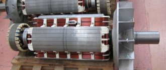
- A rotor is a moving element on the core of which there is a winding that generates electric current.
- A switching unit that removes electricity from the rotor. It is a system of movable conductive rings.
Depending on the purpose, the generator has certain design features, but there are two components that any device that converts mechanical energy into electricity has:
- The rotor is a movable one-piece piece made of iron;
- The stator is a stationary element that is made of iron sheets. Inside it there are grooves, inside of which there is a wire winding.
To obtain greater magnetic induction, there should be a small distance between these elements. By design, generators are:
- With a moving armature and a static magnetic field.
- With a fixed armature and a rotating magnetic field.
Current generator. Design and principle of operation of the generator.
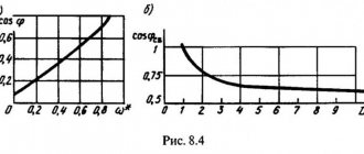
Rice. 2. The simplest principle of the design of the stator winding of a three-phase two-pole synchronous generator in the case of two coils in each phase. 1 scan of the surface of the stator magnetic system, 2 winding coils, U, V, W the beginning of the phase windings, X, Y, Z the ends of the phase windings. The poles of the inductor and, in accordance with this, the pole divisions of the stator, there may be more than two. The slower the rotor rotates, the greater the number of poles should be at a given current frequency. If, for example, the rotor rotates at a frequency of 300 r/min, then the number of generator poles to obtain an alternating current frequency of 50 Hz must be 20. For example, at one of the largest hydroelectric power plants in the world, Itaipu hydroelectric power station (see Fig. 4) generators operating at a frequency of 50 Hz are 66-pole, and generators operating at a frequency of 60 Hz are 78-pole. The field winding of a two- or four-pole generator is placed as shown in Fig. 1, in the grooves of the massive steel rotor core. This rotor design is necessary in the case of high-speed generators operating at a rotation speed of 3000 or 1500 r/min (especially for turbogenerators intended for connection to steam turbines), since at such speeds large centrifugal forces act on the rotor winding. With a larger number of poles, each pole has a separate field winding (Fig. 3.12.3). This salient-pole principle of the device is used, in particular, in the case of low-speed generators intended for connection with hydraulic turbines (hydrogen generators), usually operating at a rotation speed of 60 r/min to 600 r/min. Very often, such generators, in accordance with the design of powerful hydraulic turbines, are made with a vertical shaft.
Rice. 3. The principle of the rotor design of a low-speed synchronous generator. 1 pole, 2 field winding, 3 mounting wheel, 4 shaft The field winding of a synchronous generator
is usually supplied with direct current from an external source through slip rings on the rotor shaft.
Previously, a special direct current generator (exciter) was provided for this, rigidly connected to the generator shaft, but now simpler and cheaper semiconductor rectifiers are used. There are also excitation systems built into the rotor, in which the EMF is induced by the stator winding. If permanent magnets are used instead of an electromagnetic system to create a magnetic field, then the excitation current source is eliminated and the generator becomes much simpler and more reliable, but at the same time more expensive. Therefore, permanent magnets are usually used in relatively low-power generators (with a power of up to several hundred kilowatts). The design of turbogenerators, thanks to the cylindrical rotor of a relatively small diameter, is very compact. Their specific weight is usually 0.5...1 kg/kW, and their rated power can reach 1600 MW. The design of hydrogenerators is somewhat more complicated; the rotor diameter is large and their specific gravity is therefore usually 3.5...6 kg/kW. Until now, they have been manufactured with rated power up to 800 MW. When the generator operates, energy losses occur in it caused by the active resistance of the windings (copper losses), eddy currents and hysteresis in the active parts of the magnetic system (steel losses) and friction in the bearings of rotating parts (friction losses). Despite the fact that the total losses usually do not exceed 1...2% of the generator power, removing the heat released as a result of losses can be difficult. If we simply assume that the mass of the generator is proportional to its power, then its linear dimensions are proportional to the cubic root of the power, and its surface dimensions are proportional to the power to the power of 2/3. With increasing power, therefore, the heat sink surface increases more slowly than the rated power of the generator. If at powers of the order of several hundred kilowatts it is sufficient to use natural cooling, then at higher powers it is necessary to switch to forced ventilation and, starting from approximately 100 MW, use hydrogen instead of air. At even higher powers (for example, more than 500 MW), it is necessary to supplement hydrogen cooling with water. In large generators, the bearings also need to be specially cooled, usually using oil circulation. The heat generation of the generator can be significantly reduced by using superconducting field windings. The first such generator (with a capacity of 4 MVA), intended for use on ships, was manufactured in 2005 by the German electrical engineering company Siemens AG [3.24]. The rated voltage of synchronous generators, depending on the power, is usually in the range from 400 V to 24 kV. Higher rated voltages (up to 150 kV) were also used, but extremely rarely. In addition to synchronous generators of mains frequency (50 Hz or 60 Hz), high-frequency generators (up to 30 kHz) and low-frequency generators (16.67 Hz or 25 Hz) are also produced, used on the electrified railways of some European countries. Synchronous generators also include, in principle, a synchronous compensator, which is a synchronous motor that operates at idle and supplies reactive power to the high-voltage distribution network. With the help of such a machine, it is possible to cover the reactive power consumption of local industrial electrical consumers and free the main power system network from transmitting reactive power. asynchronous generators
can be used relatively rarely and at relatively low powers (up to several megawatts) .
In the rotor winding of such a generator, the current is induced by the stator magnetic field if the rotor rotates faster than the stator rotating magnetic field of the mains frequency. The need for such generators usually arises when it is impossible to ensure a constant rotation speed of the prime mover (for example, a wind turbine, some small hydraulic turbines, etc.). In a direct current generator,
the magnetic poles together with the field winding are usually located in the stator, and the armature winding is located in the rotor.
Since an alternating EMF is induced in the rotor winding during its rotation, the armature must be equipped with a commutator (commutator), with the help of which a constant EMF is obtained at the output of the generator (at the commutator brushes). Currently, direct current generators are rarely used, since direct current is easier to obtain using semiconductor rectifiers. Electric machine generators also include electrostatic generators
, on the rotating part of which a high voltage electric charge is created by friction (triboelectrically).
The first such generator (a manually rotated sulfur ball that was electrified by friction against a person’s hand) was made in 1663 by the mayor of Magdeburg (Germany), Otto von Guericke (1602–1686). During their development, such generators made it possible to discover many electrical phenomena and patterns. Even now they have not lost their importance as a means of conducting experimental research in physics. The first magnetoelectric generator
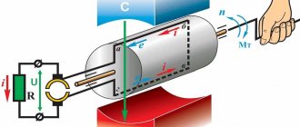
was made on November 4, 1831 by Michael Faraday, a professor at the Royal Institution of London (1791–1867). The generator consisted of a horseshoe-shaped permanent magnet and a copper disk rotating between the magnetic poles (Fig. 3.12.4). When the disk rotated between its axis and the edge, a constant emf was induced. The same principle applies to more advanced unipolar generators, which are still in use (albeit relatively rarely).
Rice.
4. The principle of construction of a unipolar generator
by Michael Faraday. 1 magnet, 2 rotating copper disk, 3 brushes. Disc handle not shown Michael Faraday was born into a poor family and after primary school, at the age of 13, he became an apprentice bookbinder. Using books, he independently continued his education, and using the Encyclopedia Britannica he became familiar with electricity, making an electrostatic generator and a Leyden jar. To expand his knowledge, he began attending public lectures on chemistry by the director of the Royal Institution, Humphrey Davy (1778–1829), and in 1813 received the position of his assistant. In 1821 he became chief inspector of this institute, in 1824 - a member of the Royal Society and in 1827 - professor of chemistry at the Royal Institution. In 1821, he began his famous experiments in electricity, during which he proposed the principle of operation of an electric motor, discovered the phenomenon of electromagnetic induction, the principle of a magnetoelectric generator, the laws of electrolysis and many other fundamental physical phenomena. A year after Faraday’s experiment described above, on September 3, 1832, the Parisian mechanic Hippolyte Pixii (1808–1835) manufactured, by order and under the direction of the founder of electrodynamics, Andre Marie Ampere (1775–1836), a generator with a manually rotated Faraday, with a magnet (Fig. 5). An alternating EMF is induced in the armature winding of the Pixie generator. To rectify the resulting current, an open mercury commutator was first attached to the generator, switching the polarity of the EMF with each half-turn of the rotor, but it was soon replaced by a simpler and safer cylindrical brush commutator, shown in Fig. 5.
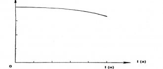
Rice.
5. The principle of the magnetoelectric generator
(a), a graph of the induced EMF (b) and a graph of the pulsating constant EMF obtained using a collector (c).
The handle and bevel gear are not shown. A generator built on the Pixie principle was first used in 1842 at his factory in Birmingham to power plating baths by the English industrialist John Stephen Woolrich (1790–1843), using it as a drive 1 liter steam engine engine With. The voltage of its generator was 3 V, the rated current was 25 A and the efficiency was about 10%. The same, but more powerful generators quickly began to be introduced at other electroplating enterprises in Europe. In 1851, the German military doctor Wilhelm Josef Sinsteden (1803–1891) proposed using electromagnets instead of permanent magnets in the inductor and powering them with current from a smaller auxiliary generator; He also discovered that the efficiency of the generator will increase if the steel core of the electromagnet is made not of massive, but of parallel wires. However, Sinsteden's ideas began to be actually used only in 1863 by the self-taught English electrical engineer Henry Wilde (1833–1919), who proposed, among other innovations, to attach an exciter machine (English exitatrice) to the generator shaft. In 1865, he produced a generator of unprecedented power of 1 kW, with which he could even demonstrate the melting and welding of metals. The most important improvement in DC generators
was their
self-excitation
, the principle of which was patented in 1854 by the chief engineer of the Danish State Railways, Soren Hjorth (1801–1870), but which did not find practical application at that time.
In 1866, this principle was rediscovered independently by several electrical engineers, including the already mentioned G. Wilde, but it became widely known in December 1866, when the German industrialist Ernst Werner von Siemens (1816–1892) used it in his compact and highly efficient generator. On January 17, 1867, his famous report on the dynamoelectric principle (self-excitation) was read at the Berlin Academy of Sciences. Self-excitation
made it possible to abandon auxiliary excitation generators (exciters), which made it possible to generate much cheaper electricity in large quantities. For this reason, the year 1866 is often considered the year of the birth of high current electrical engineering. In the first self-exciting generators, the excitation winding was connected, like Siemens, in series (serial) with the armature winding, but in February 1867, the English electrical engineer Charles Wheatstone (1802–1875) proposed parallel excitation, which makes it possible to better regulate the EMF of the generator to which it came even before the reports of sequential excitation discovered by Siemens (Fig. 6).
Rice.
6. Development of excitation systems for DC generators. a permanent magnet excitation (1831), b external excitation (1851), c series self-excitation (1866), d parallel self-excitation (1867). 1 armature, 2 excitation winding. Regulating excitation current rheostats are not shown. The need for alternating current generators
arose in 1876, when the Russian electrical engineer Pavel Yablochkov (1847–1894) working in Paris began to illuminate city streets using alternating current arc lamps (Yablochkov candles) that he produced.
The first generators necessary for this were created by the Parisian inventor and industrialist Zenobe Theophile Gramme (1826–1901). With the start of mass production of incandescent lamps in 1879, alternating current lost its importance for a time, but regained its relevance due to the increase in electrical transmission distances in the mid-1880s. In 1888–1890, the owner of his own research laboratory Tesla-Electric Co., New York, USA, the Serbian electrical engineer Nikola Tesla (1856–1943) who emigrated to the USA and the chief engineer of the AEG company (AEG, Allgemeine Elektricitats-Gesellschaft) Russian electrical engineer Mikhail Dolivo-Dobrovolsky (1862–1919) who emigrated to Germany developed a three-phase alternating current system. As a result, the production of increasingly powerful synchronous generators
for thermal and hydroelectric power plants under construction began. An important stage in the development of turbogenerators can be considered the development of a cylindrical rotor in 1898 by the co-owner of the Swiss electrical plant Brown, Boveri & Cie., BBC, Charles Eugen Lancelot Brown (1863–1924). The first generator with hydrogen cooling (power 25 MW) was released in 1937 by the American company General Electric, and with in-line water cooling - in 1956 by the English company Metropolitan Vickers.
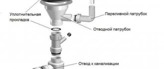
| Inverter. The design and principle of operation of the inverter. |
| Rectifier. The design and principle of operation of the rectifier. |
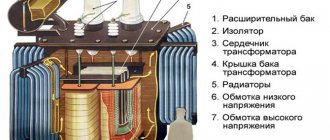
| Transformer. The design and principle of operation of the transformer. |
Classification and types of units
All electric generators can be classified according to operating criteria and the type of fuel from which electricity is generated. All generators are divided into single-phase (voltage output 220 Volts, frequency 50 Hz) and three-phase (380 Volts with a frequency of 50 Hz), as well as according to the operating principle and type of fuel that is converted into electricity. Generators can also be used in various fields, which determines their technical characteristics.
According to the operating principle
There are asynchronous and synchronous alternating current generators.
Asynchronous
Asynchronous electric generators do not have an exact dependence of the EMF on the rotor speed, but a term such as “slip S” works here. It makes that difference. The amount of slip is calculated, so there is still some influence of the generator elements in the electromechanical process of the asynchronous motor.
Synchronous
Such a generator has a physical dependence on the rotational movement of the rotor to the generated frequency of electricity. In such a device, the rotor is an electromagnet consisting of cores, windings and poles. The stator are coils that are connected according to the star principle and have a common point - zero. It is in them that electric current is generated. The rotor is driven by an extraneous force of moving elements (turbines), which move synchronously. The excitation of such an alternating current generator can be either contact or non-contact.
By engine fuel type
With the advent of generators, distance from the power grid no longer becomes an obstacle to using electrical appliances.
Operating principle
The rotating part of the generator is called the rotor, and its stationary part is the stator. An alternating current generator has a stator and a rotor, which by design can be both an armature and an inductor.
Almost all the electricity in the world's power plants is produced by alternating current generators. When the inductor rotates, a magnetic field is created, which rotates and induces an alternating electromotive force in the stator winding. Its frequency completely coincides with the rotor speed.