Single-phase transformer design
Any single-phase transformer can only operate in alternating current circuits. Due to it, the resulting electrical voltage changes to the desired value. The current obtained in this way increases, as a result of the fact that the power is actually delivered without loss. From this it follows that the main use of such a device is to output the voltage necessary to solve the problem, after which it can be used for certain purposes.
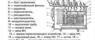
A detailed analysis of the transformer design will help you understand the operation of the device. It consists of the following main parts:
- A core consisting of materials with ferromagnetic properties;
- Two coils, the second is on a separate frame;
- Protective case (not available on all models).
Single-phase transformer design
Principle of operation
A single-phase transformer operates on a certain law, due to which the alternating electromagnetic field running in a coil induces an electromotive force in a nearby conductor. The action is called the law of electromagnetic induction, which was discovered by Michael Faraday in 1831. As a result of substantiating the law, the scientist created a general theory used in the operation of a huge number of modern electrical devices.
When the primary winding is connected to an alternating current source, an alternating current I1 flows in the turns of this winding, which creates an alternating magnetic flux in the core (magnetic core). Closing in the core, this flux couples with the primary and secondary windings and induces in them an emf proportional to the number of turns W.
Transformer operating principle
In the primary winding there is an EMF of self-induction: in the secondary winding there is an EMF of mutual induction: When connected to the secondary winding, I2 will flow to the load and U2 will be established.
What is a transformer
At its core, a transformer is an electrical current converter. Electromagnetic induction is used to change voltage.
The basic principles of operation of these devices are as follows:
- Electric current changes over time and creates a magnetic field that is subject to similar changes.
- The changed magnetic flux passing through the winding of the transformer causes the appearance of electromagnetic induction in it. Some high or ultra high frequency devices may not have a magnetic core. Ideally, there should be no loss of electricity spent on dissipation flows and heating of the windings.
Transformers can operate in various modes:
- Idling. In this case, the secondary circuit of the device is open and no current flows through it. Compensation of the power source voltage occurs by compensating the electromotive force of induction in the primary winding.
- Load mode. The secondary circuit is in a closed state. A current appears in it, under the influence of which a magnetic flux appears in the magnetic circuit. It acts in the opposite direction to the magnetic flux generated in the primary winding. The equilibrium of the induced emf with the power source is disrupted. As a result, the current in the primary winding will increase until the magnetic flux value returns to its previous level. This is the main operating mode for any transformer.
- In short-circuit mode, the secondary circuit is short-circuited. This condition allows you to determine how much useful power the transformer is losing when the wires heat up. A small alternating voltage is supplied to the primary winding. Its value must be the same as the rated current of the device.
Operating modes
Like any other converter, a single-phase transformer has three operating modes:
- Idle mode. From the name it is clear that no current will flow, due to the open secondary circuit of the device. And an idle current passes through the primary winding, the main element of which is represented by the reactive magnetizing current. The mode is used to determine the efficiency of a transformer, or to display core losses.
- Load mode. The mode is determined by the operation of the transformer with a connected source in the primary circuit, and a certain load in the secondary channel of the device. The secondary circuit is characterized by the flowing load current (calculated from the ratio of the number of turns of the winding and the secondary current) and the no-load current.
- Short circuit mode. The mode operates during the closure of the secondary circuit due to differences in potential values. In this mode, the resulting resistance from the secondary winding will be one load source. When a short circuit occurs, you can calculate the loss due to heating of the winding in the device circuit.
Also read: Single-phase cast current transformer - TPOL
Transformer operating mode
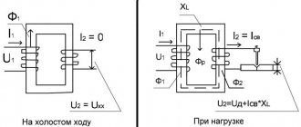
| Operating mode is the operating mode of a transformer in which a load is connected to the secondary winding (Fig. 1.6.). In no-load mode, the main magnetic flux in the core Ф0 creates a self-inductive emf in the primary winding, which balances most of the applied voltage. This will remain the case as long as the secondary winding is open. I2 will appear in it Ф2 in the same core , the sign of which, in accordance with the rule | Rice. 1.6. Transformer diagram with load |
Lenz, is opposite to the sign of the magnetic flux F1
created by the primary winding (Fig. 1.6).
As a result, the total magnetic flux in the core will decrease, and this will lead to a decrease in the emf E1
in the primary winding.
As a result, part of the applied voltage U1
will be unbalanced, which will lead to an increase in the current in the primary winding.
The current in the primary winding will increase until the demagnetizing effect of the load current stops. After this, the total magnetic flux will be restored approximately to the previous value Ф0
.
As the resistance of the secondary winding increases, the current decreases 12
and magnetic flux
Ф2
, which leads to an increase in the total magnetic flux and, consequently, to an increase
in E1
.
As a result, the balance between the applied voltage U1
and the emf
E1
: their difference will decrease, and therefore the current
I1
to a value at which the total magnetic flux will return to its previous value [4, Art. 134 – 135].
Thus, the magnetic flux in the transformer remains practically constant both in no-load mode and in variable load mode. This property of a transformer is called self-regulation ability ,
that is, the ability to automatically adjust the value of the primary current
I1
when the load current
I2
[4, art. 134 – 135].
Transformer efficiency
The transformation of electrical energy in a transformer is accompanied by losses. Transformer efficiency (efficiency) is the ratio of supplied active power to consumed (10) [4, art. 136]:
; (10)
where P1
– power consumed from the network
,
P2
– power supplied to the load.
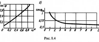
For practical determination of efficiency. transformer at rated load, it is necessary to measure the power in the primary and secondary windings. This measurement can be greatly simplified by including a resistive load in the secondary winding. Then cos φ ≈ 1
(the leakage flux is small), and the power
P2
can be calculated from the readings of the ammeter and voltmeter included in the secondary circuit.
This method of determining efficiency called the direct measurement method .
It is very simple, but has two significant drawbacks: low accuracy and inefficiency.
The first of them is due to the fact that the efficiency transformers is very high (up to 99%): therefore the power P2
and
P1
sometimes differ little in size. In this case, minor errors in instrument readings will lead to large errors in the efficiency value. The inefficiency of this method is associated with high energy consumption during the test, since the transformer has to be loaded to its rated power. Therefore, the direct measurement method has not found industrial application, but can be used for low-power transformers with low efficiency. (for example, in educational practice).
In practice, efficiency transformers are determined by the indirect method ,
those. by separately determining losses, based on the fact that the efficiency transformer can be presented in the form (11) [4, art. 137]:
; (11)
where Rst
– losses in steel (in the core),
Rm
– losses in copper (in windings).
Steel losses and copper losses are measured in open-circuit and short-circuit tests, respectively.
In the no-load test, in which the rated voltage is applied to the primary winding and the secondary winding is left open-circuit, steel losses ,
those.
losses due to hysteresis and eddy currents. Since at the rated voltage on the primary winding the magnetic flux is practically constant, regardless of whether the transformer is loaded or not, the losses in steel for it are a constant value. Thus, we can assume that in no-load mode the energy consumed by the transformer from the network is spent only on losses in steel, therefore the power of these losses is measured with a wattmeter connected to the primary winding circuit. This does not take into account the heating losses of the primary winding wire by the no-load current. But this current is small, and the losses from it are also small. In this experiment, the transformation ratio k
and the no-load current
I
01 are also determined.
If the secondary winding of the transformer is short-circuited, and such a reduced voltage is applied to the primary winding that the currents in the windings do not exceed the rated values, then the energy consumed by the transformer from the network is spent mainly on heat losses in the wires of the transformer windings. When the secondary winding is short-circuited, a reduced voltage is supplied to the primary winding, so the magnetic flux is very small and losses in the steel, depending on the value of the magnetic flux, are also small. This experience is called a short circuit .
Consequently, a wattmeter connected to the circuit of the primary winding of the transformer in this experiment will show the power corresponding to the losses in copper (
R
m) [4, Art. 137].
Transformation ratio
Transformers can be step-up and step-down, to determine this you need to find out the transformation ratio , with its help you can find out which transformer. If the coefficient is less than 1, then the transformer is step-up (this can also be determined by the values; if there is more in the secondary winding than in the primary, then it is step-up), and vice versa, if K>1, then it is step-down (if there are fewer turns in the primary winding than in the secondary).
Formula for calculating the transformation ratio
- U1 and U2 - voltage in the primary and secondary windings,
- N1 and N2 - number of turns in the primary and secondary windings,
- I1 and I2 - current in the primary and secondary windings.
Learn more about calculating the transformation ratio.
Operating principle
The operating principle of a single-phase transformer is quite simple and is based on the generation of electromotive force (EMF) in the windings of a conductor, which is in a moving magnetic field and generated using alternating I. When electricity passes through the windings of the primary coil, a magnetic flux (F) is created, which penetrates the secondary reel. Due to the closed design of the magnetic circuit, the power lines Ф have a closed structure. To obtain optimal power T, it is necessary to place the winding coils at a close distance relative to each other.
Based on the law of electromagnetic induction, a change in F occurs and an EMF is induced in the primary winding. This quantity is called self-induction emf, and in the secondary – mutual induction emf.
When a consumer is connected to the primary winding T, electrical energy will appear in the circuit, which is transmitted from the primary winding through a magnetic circuit (the coils are not galvanically connected). In this case, only F serves as a means of transmitting electricity. Transformers vary in design features. Upon achieving maximum magnetic coupling (MC), T are divided into the following types:
- Strong.
- Average.
- Weak.
With weak MS, a significant loss of energy occurs and Ts of this type are practically not used. The main feature of such Ts is open cores.
The average MC level is achieved only with a completely closed magnetic circuit. One example of such a T is the rod type, in which the windings are located on iron rods and are connected to each other by plates or yokes. The result of this design is a completely closed core.
An example of a strong MC is an armor-type T, the windings of which are located on one or more coils. These windings are located very close, which ensures minimal loss of electrical energy. The magnetic circuit completely covers the coils, creating a stronger F, which breaks into 2 parts. In transformers of this type, the coupling fluxes between the windings are almost equal.
Classification of single-phase transformers
Power transformer
The transformer is used in the conversion of electricity in networks and in devices used to obtain and use the required amount of electrical energy. “Power” implies its operation with high voltage. The use of power transformers is forced by different indicators of the operating power of power lines, networks in the urban area, output voltage for end objects, as well as for the general operation of electrical devices and machines. Power varies from a few units of volts to hundreds of kilowatts.
An autotransformer is one of the types of converter where the primary and secondary windings are not separated, but are directly connected to each other. Due to this, both electromagnetic and electrical connections are formed between them. The winding is accompanied by at least three terminals; by connecting to each of them, different powers can be used. The main advantage of such a transformer is its high level of efficiency, since not all of the voltage is converted, but only a certain part. The difference is especially noticeable when the input and output power are slightly different.
Current transformer
Such a transformer is mainly used to reduce the primary winding current to the desired value suitable for measurement, protection, control and signaling applications. In addition, it is used in galvanic isolation (transmission of electricity or signal by connected electrical circuits, while there is no electrical contact between them).
Also read: Three-phase dry voltage transformer - NTS
The normalized value of the secondary winding current parameters is 1 A or 5 A. The primary winding of the transformer is connected stepwise into the circuit with the load, while the alternating current is controlled, and measuring devices are connected to the secondary winding.
The secondary winding of the current transformer must be constantly in near-short circuit mode. After all, with any option of disconnecting the circuit, high power is supplied to it, which can knock out the insulation and cause the failure of the switched-on devices.
High voltage CT(left) and low voltage CT(right)
Read more about the current transformer.
Voltage transformer
Such a transformer receives energy from a voltage source. It is mainly used to change high voltage to low voltage in various circuits, including measuring and relay protection and automation. It has the ability to isolate protection and measurement circuits from high-power circuits.
High voltage transformer (left) and low voltage transformer (right)
Read more about TN.
Pulse transformer
Used to modify pulse signals with pulse response accurate to tens of microseconds. In this case, the pulse shape is accompanied by only slight distortion. The main purpose of a pulse transformer is to transmit a rectangular electrical pulse. Used to convert short video voltage pulses, often played back with high duty cycle.
An important parameter when using a pulse transformer is the undistorted type of transmission of pulsed voltage systems. When the input of a device is influenced by powers that differ from each other, it is important to obtain a voltage that exactly matches the same shape, perhaps with a different amplitude or different polarity.
Types of pulse transformers
Read more about the pulse transformer.
Types of transformers
Modern transformer devices have many varieties and are used in a wide variety of fields.
Power transformers
Electricity is transmitted over a distance using power transformers. These low-frequency devices perform its reception and conversion. They received the name power because they work with voltages that can reach more than 1000 kilovolts.
In cities, such transformers lower the voltage to 0.4 kV, turning it into 380 or 220 volts necessary for normal consumption. These devices are equipped with two, three or more windings, which allows you to simultaneously convert voltage from several generators at once. Normal temperature balance is maintained using transformer oil, and in particularly powerful devices an active cooling system is additionally installed.
Network transformers
Until recently, almost all electrical appliances had single-phase network transformers installed. With the help of these devices, the usual network voltage of 220 volts was reduced to the required level of 5, 12, 24 and 48 V.
In network transformers, it was practiced to install several secondary windings at once. This design provided power to different parts of the circuit from several power sources at once. For example, an incandescent transformer was necessarily present in circuits with radio tubes.
Modern devices of this type use W-shaped, toroidal or rod cores. They are based on plates made of electrical steel. With a toroidal shape of the magnetic circuit, the transformers are more compact; the winding passes over the entire surface, leaving no empty sections of the yoke.
Autotransformers
Autotransformers are also low-frequency devices in which the primary and secondary windings complement each other. There is not only a magnetic but also an electrical connection between them. A single winding is equipped with several terminals at once, which allows you to obtain different voltage values. These devices are lower in cost because less wire is needed for the windings, as is less steel for the core. As a result, the total weight of the device is also reduced.
Peculiarities
As a rule, single-phase transformers are used in electrical networks and as power sources for various devices.
Based on the fact that the heating of a wire is directly proportional to the square of the current flowing through the wire, when transmitting energy over long distances it will be more profitable to use high voltages and low currents. To avoid damage to electrical appliances and reduce the amount of insulation at home, it is better to use low powers.
Also read: Pulse transformer
In view of this, to reduce the cost of transporting electrical energy in the general power grid, power transformers are used in large quantities: first, they increase the voltage of generators at power plants before transmitting energy via cable, and after transportation, they reduce the voltage of power lines to the required level for widespread use.
Single-phase transformers
Application of transformers in electrical networks
Energy losses for heating the wire are directly proportional to the square of the current that passes through the wire. When transmitting electricity over long distances, it is advantageous to use low currents and high voltages. For safety reasons, as well as in order to reduce the weight of the insulation layer in everyday life, medium voltages should be used - transformers are used for the profitable transportation of energy in the network. The devices first increase the voltage of generators at stations before transporting current, and then reduce the voltage in the line to an optimal level.
The electrical network has three phases, so three-phase transformers are used to convert voltage. The core of such a device is common to all phases. Despite the high operating efficiency of the equipment, large amounts of heat are generated in powerful installations - therefore, there is a need to use a special cooling system. The transformer is placed in a tank filled with technical oil or a special liquid, which begins to circulate under the influence of convection or between the radiators and the tank forcibly. In some cases, the oil can be cooled with water.
Exploitation
When using single-phase transformers, safety precautions are given a special place. This is due to the fact that the device is under high voltage located on the primary windings. When connecting and installing a transformer in electrical circuits, it is important to follow a number of rules to avoid breakdowns and malfunctions of the device:
- To prevent the windings from failing (burning out), it is necessary to install short circuit protection on the secondary circuit;
- It is necessary to control the temperature conditions of the core and windings. It is advisable to install a cooling system that prevents a critical increase in temperature during operation.
In the case of different loads from the electrical network, its voltage also changes. For stable operation of devices receiving energy, it is necessary that the voltage does not change from a set level above the permissible range. In view of this, it is permissible to use methods of voltage regulation in the network.
What are its advantages and disadvantages
Any electrical device has a number of advantages and disadvantages. Single-phase electrical transformers are no exception to this. They have more advantages than disadvantages. The main ones are:
- have one of the highest coefficients of performance (efficiency), which is 98%;
- They cool well and have increased resistance to overloads and short-term power surges;
- environmental safety of dry type. There is no oil in them, which means that nothing can harm the environment even after disposal;
- no need to comply with special fire safety measures at transformer installation sites;
- relatively small sizes, allowing the devices to be installed in small compartments.
You might be interested in Mercury 201 Electricity meter Transformer: symbol and description
These devices are not without a number of disadvantages, which depend on their type and place of use:
- difficult maintenance if the device is oil-based. It should be regularly checked for breakdown and leakage of rubber gaskets, the replacement of which is quite difficult;
- dry single-phase devices do not tolerate high humidity, wind, chemical and physical influences, as well as pollution;
- high cost of dry transformers compared to oil transformers.
Conventional device for single-phase networks