Transformers are static electrical devices with no moving parts that convert electrical energy from one voltage and current to another. The frequency of the electric current remains constant.
Transformers are classified by function: step-up or step-down. Step-up transformers increase the incoming voltage, and step-down transformers reduce the output voltage. The input voltage is called the primary voltage, and the output voltage is called the secondary voltage. The transformer can also be used for galvanic isolation.
Typically, step-up transformers are located in power plants, increasing the voltage supplied from the power plant to distribution networks over long distances. Step-down transformers, on the other hand, reduce the voltage of distribution networks received at the local distribution level. The long distance flow is first reduced to a level acceptable for local distribution and then reduced again at each consumer node (residential buildings and offices).
Necessity of Transformers
When transmitting electrical energy, both over long and short distances, the power supply system experiences its own losses. The higher the current in the line, the greater the losses (at lower voltage, since the power transferred is the same). For this reason, in order to transmit electricity over long distances, it is necessary for the electricity to have the highest voltage possible and the lowest possible current. However, high voltage is not safe for consumers and is not suitable for most electrical appliances. Household electrical appliances are typically rated at 220V (110V in the US).
Transformers convert electrical power between the high voltage, low current needed for transmission over long distances, and the low voltage, high current needed for consumer use.
Additionally, power lines are typically made of copper to minimize transmission losses. Copper has the lowest electrical resistance of any conductive material.
Which transformer is called a step-up transformer?
A step-up transformer is an ordinary transformer (see the purpose and principle of operation of a transformer) that increases the voltage value of an electric current. On the primary winding it is lower, and on the secondary winding it is higher. Thus, the voltage at the output of the device is higher and, due to a certain number of turns of the winding and cross-section, has the desired value.
The principle of operation of a step-up transformer is the value of K (transformation ratio).
When K>1 the transformer is a step-down transformer, and when K is a step-up transformer circuit
Application of step-up transformers
The devices are installed in electrical lines and power supplies of consumer points. According to the Joule-Lenz law, as the current increases, heat is released, which heats the wire. To transmit energy over long linear distances, the voltage is increased and the currents are decreased. When reaching the consumer, the power is reduced, since for safety reasons it would be necessary to use massive insulation.
At the beginning of the chain, a step-up transformer is installed, and at the receiving point the indicators are reduced. Such combinations are used repeatedly along power lines, achieving favorable conditions for transporting electricity and creating acceptable values for the consumer.
Due to the presence of three phases in the network, three-phase units are used for energy transformation. Sometimes a group is used in which the devices are combined into a star model, with a common conducting rod.
Although the efficiency of high-power units reaches almost one hundred percent, a lot of heat is still generated. A typical 1 GW power plant transformer produces several megawatts. To reduce this phenomenon, a cooling system has been developed in the form of a tank containing non-flammable liquid or transformer oil and a strong air heat distribution device. Cooling is often water-based; the dry principle is used at low power.
Step-up toroidal transformer
As you understand, when we say “toroidal transformer,” we usually mean a network single-phase transformer, power or measuring, step-up or step-down, whose toroidal core is equipped with two or more windings.
A toroidal transformer works in principle the same way as transformers with other forms of cores: it lowers or increases the voltage, increases or decreases the current - it converts electricity. But a toroidal transformer, with the same transmitted power, is smaller in size and lighter in weight, that is, has better economic indicators.
The main feature of a toroidal transformer is the small total volume of the device, reaching up to half in comparison with other types of magnetic cores.
The laminated core is twice as large in volume as a toroidal strip core with the same overall power.
Therefore, toroidal transformers are more convenient to install and connect, and it is no longer so important whether we are talking about internal or external installation.
Any specialist will say that the toroidal core shape is ideal for a transformer for several reasons:
- firstly, saving materials in production,
- secondly, the windings evenly fill the entire core, distributed over its entire surface, leaving no unused spaces,
- thirdly, since the windings are shorter, the efficiency of toroidal transformers is higher due to the lower resistance of the winding wires.
Winding cooling is another important factor.
The windings are effectively cooled by being arranged in a toroidal shape, hence the current density can be higher.
Losses in the iron are minimal and the magnetizing current is much lower. As a result, the thermal load capacity of the toroidal transformer turns out to be very high.
Energy savings are another plus in favor of a toroidal transformer.
Approximately 30% more energy is saved at full load, and approximately 80% at idle, compared to laminated magnetic cores of other forms. The dissipation index of toroidal transformers is 5 times less than that of armored and rod transformers, so they can be safely used with sensitive electronic equipment.
With a power of a toroidal transformer up to a kilowatt, it is so light and compact that for installation it is enough to use a metal pressure washer and a bolt. All the consumer needs to do is select a suitable transformer based on load current and primary and secondary voltages. When manufacturing a transformer at the factory, the cross-sectional area of the core, the area of the window, the diameters of the winding wires are calculated, and the optimal dimensions of the magnetic circuit are selected, taking into account the permissible induction in it.
Why are voltage-increasing transformers installed near power plants?
Any conductor has its own resistance and therefore heat losses inevitably occur in power lines due to heating of the conductor . The amount of heating is proportional to the square of the current in the circuit, so by increasing the voltage to hundreds of kilovolts, we, according to Ohm’s law, lower the current, and therefore reduce heat losses and the size of power line conductors, saving materials and costs.
- See the principle of operation of transformers in the transmission of electrical energy over a distance
Video: Step-up transformer
Application of a step-down transformer
Power plants produce electricity at 20 kV, which is then increased to 330 kV (and sometimes higher) for distribution over long distances. When received at the local distribution station, the voltage is reduced to 6.10 kV using a step-down transformer. Then, for distribution to individual consumers, another step-down transformer is used, which reduces the voltage to standard 380 V (220 V), suitable for consumer use.
Household voltage in most areas is 220 V. However, not all over the world uses 220 V in household outlets. For example, in the United States, household voltage is 110 V. Connecting a 220 V device to a 110 V outlet may damage the device. Fortunately, there are inexpensive transformer adapters (picture below) that completely solve this problem.
Transformer operation
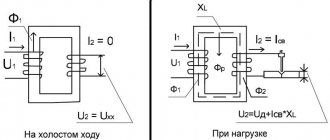
Transformers operate on the principle of mutual induction. A changing magnetic field in one turn of wire induces an electromotive force (EMF) in an adjacent turn of wire, inductively coupled to the first. Simply put, a transformer consists of two coils of copper wire with high mutual inductance. These coils are electrically separated, while at the same time they share a common magnetic circuit (picture below).
In a step-down transformer, the secondary winding has fewer turns than the primary, which reduces the voltage at the output of the device.
The primary winding, which is the first set of coils, is connected to an AC voltage source. The secondary winding is connected to the load, distributing electricity from the transformer.
Alternating current flowing at the primary voltage creates an alternating magnetic flux. It induces a similar current in the secondary coil, creating a secondary voltage. Here, the reduced number of secondary coil windings effectively reduces the resulting voltage, hence "stepping down" the voltage to a lower value while maintaining a constant frequency.
Note that as the voltage decreases, the current increases to maintain equal frequency between the primary and secondary windings. For this reason, the secondary winding in step-down transformers usually has a larger wire cross-section than the primary. Since the current in the primary winding is low, large gauge wire is not required to connect the primary winding. Conversely, increased current flowing through the secondary winding requires an increase in the cross-section of the conductor. If the wire in the secondary coil is too thin, it will melt due to overheating, causing the transformer to fail.
Design features
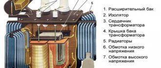
This is a very useful device. A transformer is a device that consists of a core with two windings. They must have the same number of turns, and the core itself is made of electrical steel. Voltage is applied to the input of the device, an electromotive force appears in the winding, which creates a magnetic field.
The basic principle of operation of the device.
The turns of one of the coils pass through this field, due to which a self-inductive force arises. In the other, a voltage arises that differs from the primary by as many times as the number of turns of both windings differs.
With its help, we can easily reduce the voltage and current in AC circuits. The advent of transformers made the transmission of electricity over long distances a practical reality. Transformers make it possible to reduce losses on the wires of power lines (connecting generating stations with loads) to reduce alternating current.
At both ends (both the generator and the loads), transformers step down voltage levels to safer values and reduce the cost of the equipment involved.
A step-down transformer can be of various types and types: single or three-phase, with an open housing or with a protective casing. One of the most important characteristics of the device is the transformation ratio, which should not exceed 1. Basic facts about step-down transformers are shown in the figure below.
Basic facts about step-down transformers.
Depending on the modification, the device converts electric current of different initial voltages, which can reach 660V. The transformer that steps down to 220V is most widely used. There is also a transformer that steps down to 380 volts.
A magnetic core is a set of elements of ferromagnetic material (usually electrical steel), which are assembled in a certain geometric shape. The main magnetic field of the step-down transformer is localized in it.
The entire magnetic system, together with all its components, is called the core. In this case, the part where the main windings are located is called the rod. And the part needed to complete the magnetic circuit is the yoke.
In accordance with the arrangement of the rods in space, the step-down transformer can have a flat, spatial, symmetrical or asymmetrical magnetic system.
In accordance with the requirements for each case, the output voltage can be different: for example, a transformer that reduces to 36 Volts, as well as 12, 24, 42V, etc. The video describes in detail the principle of operation of the device.
Which core is better
Step-down voltage transformers differ in their design features. Manufacturers make a choice in favor of one of two concepts - armored or rod.
The fundamental difference between the technical solutions is that in the first case, the windings are enclosed in an armor-type core, and in the second, the core is enclosed in rod-type windings.
Moreover, in devices of the first type, the axis of the windings can be located vertically or horizontally, while in the second case, the axis is placed vertically.
It will be interesting➡ What is the difference between voltage transformers and current transformers
However, the production method does not affect the performance and reliability of the device. The enterprise chooses the option that it considers best from the point of view of organizing the technological process.
Core and coils of a step-down transformer.
Manufacturing Considerations
Transformers are an expensive but important element of the power supply system. Transformers require large capital expenditures to purchase and are expected to operate for their entire predicted service life. In reality, however, transformers typically fail at about half their expected life. Improperly repaired windings, on-load tap-changers and bushings are often the root cause.
However, inadequate maintenance plans are not the only culprit. Transformers are often not suitable for their intended use, placing unnecessary stress on the device. Even though transformers are completely static and have no moving parts, the amount of current flowing through the windings causes wear on the windings themselves. The same goes for tap changers and bushings. Over time, the integrity of these materials is compromised, resulting in mild to critical failure.
To prevent premature failure, transformers should be selected carefully. After installation, commissioning must also be carried out carefully. Operating conditions must be carefully monitored and maintenance plans must be carried out regularly and thoroughly. With these provisions in place, transformers are likely to provide optimal performance throughout their predicted service life.
Self-production
The design of the transformer is quite simple, so it is not difficult to make it yourself. But before proceeding directly to its manufacture, it is necessary not only to prepare the material and tools, but also to perform a preliminary calculation.
How to make a step-down transformer with your own hands can be considered using a specific example. Let the task be to manufacture a converter from 220 V to 12 V with an output current of 10 A.
It is unlikely that you can make the core yourself, so it is better to use an unnecessary transformer of any type. You will need to carefully disassemble it and remove the “hardware” from there.
The next step is to make the frame. You can use various materials, for example, fiberglass. To calculate it, you can use the Power Trans program. It is worth noting that although this application can also calculate the number of turns, it is better not to use it for these purposes, due to not entirely correct results.
In the program, you can select the type of core, as well as set the cross-section of the core, windows and power of the product. Then click on calculation and get a finished drawing with dimensions. Next, all that remains is to transfer the drawing onto the textolite and cut out the required number of parts. After all the elements are prepared they are assembled into a frame.
Now you can proceed to preparing the insulating gaskets. They will be necessary to isolate the layers from each other. They are cut into strips of varnished fabric, fluoroplastic, mylar, or even thick paper, for example, which is used for baking. It is important to note that the width of the strip is made a couple of millimeters larger, and it is not recommended to mark the cutting lines with a graphite pencil (graphite conducts current).
At the last stage, the wire is prepared. Since it will be necessary to wind a 220 V 12 V 10a transformer, that is, a step-down transformer, the secondary coil will be made with a thick wire, and the primary coil with a thin wire.
Design calculation
Design calculations begin by finding the power that the secondary winding must withstand. Substituting into the formula: P = U * I, the values given to the conditions b for the secondary coil, you get: P 2 = 12 * 10 = 120 W. Assuming that the efficiency of the product will be about 80% (the average value for all transformers), we can determine the primary power: P = P 2/0.8 = 120/0.8 = 150 W.
Based on the fact that power is transmitted through the core, the value of P1 will depend on the cross-section of the magnetic circuit. The cross section of the core is found from the expression: S = (P 1)½ = 150 = 12.2 cm2. Now you can find the required number of turns in the primary winding to produce one volt: W = 50/ S = 4.1. That is, for a voltage of 220 volts you will need to wind 917 turns, and for a secondary voltage - 48 turns.
You may be interested in this How a voltmeter works
The current flowing through the primary coil will be equal to: I = P / U = 150/220 = 0.68 A. Hence the diameter of the primary winding wire is calculated by the formula: d = 0.8 * (I)½ will be 0.66 mm, and for the secondary - 2.5 mm. The cross-sectional area can be taken from reference tables or calculated using the formula: S = 0.8 * d 2. It will be 0.3 mm2 and 5 mm2, respectively.
If suddenly a wire of such a cross-section is difficult to get, then you can use several conductors connected to each other in parallel. In this case, their total cross-sectional area should be slightly larger than the calculated one.
Winding technique
To wind the product, the made frame must be clamped on the axis and centered . It is better to first wrap the wire around some cylindrical object. For example, a spool of thread or a piece of pipe. A coil of wire is placed opposite the clamped frame. The wire is placed on the base and made several turns around it. Then they begin to rotate the frame body. In this case, you should carefully ensure that each turn lies next to the other and does not intersect it. After each layer, two turns of insulation are applied.
Once the primary winding is wound, the wire must be brought out to the side to form a lead. The rest of the wire is cut off. Before applying the secondary winding, several layers of insulation are laid and the whole process is repeated, but with a wire of a thicker cross-section. Upon completion of the work, the free ends of the coils are soldered to the terminals. Using a tester, the coils are checked for breaking.
There are some nuances when winding that it is advisable to know. During winding, the wire may accidentally break. In this case, you will need to strip the broken ends, twist them and solder them. Carefully insulate the soldering area, for example, by placing two layers of insulating paper. When winding, to increase the electrical strength of the product, it is recommended to impregnate each layer. This prevents vibration of the wire. Epoxy or acrylic based varnishes are used as impregnation.
Now all that remains is to connect the transformer from 220 to 12 to the power source. The connection to it occurs in a parallel circuit. Using a multimeter you can check the output voltage. To do this, it switches to the AC signal measurement mode.
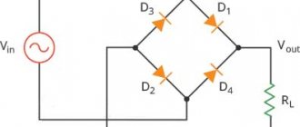
If in the future it is necessary to obtain a constant signal, then a diode bridge (rectifier) with an electrolytic capacitor (smoothing filter) is connected to the secondary winding of the transformer. But it should be taken into account that for a current of 10 amperes you will need a corresponding rectifier unit capable of withstanding such a current with a margin of about 15%.
Thus, even a novice radio amateur can make a step-down transformer on his own. The main thing is to perform the correct calculation. And the manufactured product will certainly find its application.
Windings
Carefully select the type of metal from which the transformer windings are made. Here the goal is to minimize resistance in the wires while increasing electrical conductivity. In this case, copper is best, although it is usually more expensive than aluminum, which is an alternative.
In the long run, copper is generally the most cost-effective option as it offers less electrical resistance than alternative materials. This reduced resistance results in less power loss, increasing the long-term efficiency of the equipment. An additional benefit is reduced heat generation in the system, as electrical resistance generates heat when using alternative materials.
It is important to understand the physical layout of the windings. This arrangement must be consistent with the expected operating conditions.
