Main types of electromagnetic relays
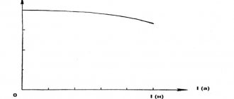
The main purpose of these devices is switching at high load currents. In other words, they perform the functions of switches that, through weak currents, turn on circuits with high currents. If such a circuit is connected directly without a relay, then the wiring and button simply will not withstand high currents and will melt. The relay takes on a large current load and makes switching using powerful contacts.
Electromagnetic switches are divided into two main groups:
- Neutral relays have the simplest design. It includes a contact and magnetic system. Each contact group includes two fixed and one common moving contact. The magnetic system consists of a movable armature, a core, a winding and a yoke.
- A polarized relay consists of the same systems. However, the magnetic system contains two cores with windings, as well as a contact rod and a permanent magnet.
Unlike neutral ones, electromagnetic polarized devices are able to operate depending on the polarity of the control signal. Electrical sheet steel is used to make the core, which can significantly increase the speed of operation of the device.
Using a polarized relay in a car.
Material from Maxim from the site: https://www.drive2.ru
So, another useful modification of minimal complexity. With frequent and not very long trips during the day, you have to turn off the headlights and radio every time you get out of the car, and when you return, turn everything back on. So I thought about the problem - how to automate this process by entrusting it to the car alarm unit, while providing for blocking the switching off of the dimensions when this is necessary for reasons of road safety.
I ask in advance for comments like “My radio turns off with the ignition switch, and why is all this necessary?” don't write, just close this page. The purpose of this article, like the others in my blog, is to clearly describe the approach and the element base used in implementing the task. Let me make a reservation right away that what is stated below is applicable to security systems that have additional programmable outputs (service channels). For example, StarLine, Sheriff, Pantera, etc. have 4 or more additional channels. In my fairly budget version Sheriff-ZX725 – 6 extra. channels. Gradually 4 channels were used - ex. trunk lock; glass closer, ex. radio and dimensions, polite light when disarming. . If these channels are not available, it is possible to connect to door central locking actuators as an option. Requirements for improvement: - simplicity and repeatability; - minimum current consumption (or even better - its absence!); — reliability; - low cost of parts. If you, dear reader, look through the forums, you will find many diagrams on ordinary relays connected to the central locking system, alarm system (to the engine blocking channels). Their main drawback is the current consumption of the relay when it is on, which is about 0.05-0.2A (depending on the type). It turns out the following: the relay is energized either when the alarm is off or when it is on - depending on the specific circuit design. Meanwhile, there is another type of electromagnetic relay - a polarized relay - quite interesting in its functionality and widely used in automation equipment. It is described in more detail here: electricalschool.info/spr…lektromagnitnye-rele.html
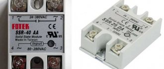
So: we find relays HFD2/012-M-L2-D, (HFD2/012-S-L2-D), RT314F12 or similar ones, widely available for sale. The cost (today) is about 50 UAH. / 100 rub. ($2.1). Link to parameters: www.dart.ru/cataloguenew/…relays_hf/html/hfd2.shtml
Polarized relay
Briefly about the theory . A polarized relay contains two independent windings and two groups of (mechanically connected) switching contacts, just like a conventional relay. The principle of operation is somewhat different from a conventional relay - to switch the contact groups, a short pulse, about 0.1 s, applied to one of the windings is sufficient. When a pulse is applied to another winding, the contact groups switch to the opposite state. Everything is extremely simple. The relay is more like a “memory cell” - it maintains its state without power. This is very attractive in this task. Now about the connection.
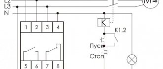
We program the algorithm for the operation of additional channels. In different security systems they are called differently, so let’s call them conventionally “channel A, channel B.” Channel A must be programmed for the appearance of a negative pulse (short to ground for 0.5 s or more) when the car is armed, channel B – a negative pulse when disarmed. In my case, these same channels are used to control the PWM-200 glass closer. The circuit can be assembled by “hinged mounting” by soldering wires to the terminals, bending them and placing them in heat shrink, or placing everything on a breadboard with screw terminals. The diodes are protective and do not need to be installed. We use one group of contacts to control the radio (at the break in the red wire). The second group of contacts breaks the side lights circuit (into the break of the white-black wire) from the side position switch. Locking button SB1 - designed to block the disabling of the lights, for example when parking on the roadway and other cases, at the discretion of the driver and for reasons of road safety.
Topic 18. Neutral and polarized relays.
18>
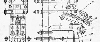
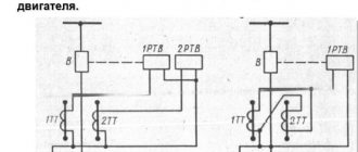
In addition to neutral relays such as RPN and RES - 14, polarized relays are used. They have high sensitivity, high response speed and control of currents in two directions. A polarized relay (Fig. 25 a) consists of a permanent magnet 1,
2 pole pieces,
3 control windings,
4
armatures and 5 contact screws. The relay magnetic circuit is built according to a differential (branched) circuit.
A permanent magnet with poles N
and S creates magnetic fluxes
F1
and F2 passing through the pole pieces and air gaps
a1
and a2.
The magnitudes of the fluxes Ф1 and Ф2 depend on the air gaps a1
and
a2
, respectively: the larger the air gap, the lower the magnetic flux value.
In the left position of the armature (see Fig. 25 a) a1 <a2,
therefore, Ф1 > Ф2 and therefore the relay armature will be attracted to the left pole piece, and the armature tongue will be pressed against the left contact screw.
In order for the armature to be thrown to the right contact, it is necessary to pass a current pulse through the control windings. When current flows through the relay windings, a magnetic flux Fi is created, which passes sequentially through both air gaps. The direction of the flow Фi should be opposite to the flow Ф1 and its value is greater than the difference between the flows Ф1-Ф2. If the specified conditions are met, the anchor, under the influence of the flow Фi, will be thrown to the right contact screw. After turning off the current, the armature remains attracted to the right pole piece, since now the air gap a1>a2
and, therefore, Ф1< Ф2.
Thus, a polarized relay has two sources of magnetomotive force, which create two magnetic fluxes: the working one, created by the electromagnet windings, and the polarizing one, created by the permanent magnet. To return the relay armature back (to the left contact screw), it is necessary to pass a current pulse through the relay windings in a different direction.
The main parameters of a polarized relay that determine the quality of its operation are:
sensitivity, characterized by the minimum current value at which the relay armature is transferred to another position (operation current); armature starting time - the time during which the current in the relay windings increases from zero to the operating current value.
Figure 25 – Design of a polarized relay
The quality of relay operation largely depends on its adjustment. Adjusting the polarized relay consists of setting the air gaps b1
and
b2
between the armature and the pole pieces (Fig.
25 b).
The adjustment can be carried out neutrally or predominantly.
Neutral regulation is characterized by the fact that when current pulses of equal duration and amplitude in both directions are passed through its winding, the armature is closed with each contact for the same time. Typically, polarized relays regulate neutrally. In this case, the distance b 1
between the pole piece and the armature in the left position of the armature and.
the corresponding distance b2
for The forces that hold the armature in one and the other state in the absence of current in the windings are also the same.
When adjusting with a predominant distance b1
and
b2
are performed differently, which leads to different values of operating currents when switching the armature from one state to another and vice versa.
Adjustment of distances b1
and
b2
is carried out using contact screws 5. Checking the relay adjustment is carried out using special devices IP-5, DINIR, etc.
The most widely used devices in rural automatic telephone exchanges (for receiving inductive signals in RSL sets) are polarized relays of the following types: TRM, RP-4 and RP-5 (small-sized). The latter have higher sensitivity than TRM relays; the RP-5 relay differs from the RP-4 relay in that in the initial state its armature is in the middle position, i.e., it does not touch the contact screws.
18>
Date added: 2020-06-09; views: 120; ORDER A WORK WRITING
Find out more:
Advantages and disadvantages
Like any element, relays have their advantages and disadvantages, however, despite the disadvantages, in some cases it is simply impossible to do without the use of these devices.
pros
- Simple design
- Easy to repair, you can always disassemble it to clean contacts or replace individual elements
- Low contact resistance
Minuses
- Limited resource due to mechanical elements used
- Contacts sometimes burn out
- Low speed when triggered, unlike semiconductor elements, a mechanical device is a hundred times slower than an electronic device, but the trigger speed is still quite high
- Possible contact rattling if there is insufficient voltage on the coil
- Clicking noise when switching
Polarized electromagnetic relays
Unlike the previously discussed neutral electromagnetic relays, in a polarized relay the direction of the electromagnetic force depends on the polarity of the DC signal in the winding. The polarization of these relays is carried out using a permanent magnet.
There are many design varieties of polarized relays, which are classified according to a number of characteristics. According to the design diagram of the magnetic circuit, relays with serial, parallel (differential) and bridge magnetic circuits are distinguished, according to the number of control windings - single and multi-winding, according to the method of setting the contacts (the number of stable positions of the armature) - two- and three-position.
Polarized relays can also be used as vibration converters, but they are most widespread in low-power automation, especially in tracking systems when controlling reversible motors.
The advantages of polarized relays include: high sensitivity, which is characterized by low operating power and amounts to 10-5 W; large control coefficient; short response time (a few milliseconds).
The disadvantages compared to neutral electromagnetic relays are the following: the design is somewhat more complicated; large overall dimensions, weight and cost.
Polarized relays use differential and bridge circuits of magnetic circuits, which have many varieties (the name of the circuits is determined by the type of electrical equivalent circuit of the electromagnetic system). In Fig. Figure 11.11 shows a polarized relay with a differential magnetic circuit.
The relay armature is acted upon by two fluxes independent of each other: flux Ф0(n), created by a permanent magnet 3
and independent of the operating state of the circuit in which the relay is connected, and the operating (control) flux Fe(p), created by magnetizing coils 1 and 1' and depending on the current flowing through their windings.
Electromagnetic force acting on the armature 4,
Thus, it depends on the total action of the flows Fe(p) and Ф0(n). A change in the direction of the electromagnetic force when the polarity of the current in the working winding changes occurs due to the fact that the direction of the working flow relative to the polarizing one changes.
The polarizing flow Ф0(п) passes through the armature and branches into two parts - Ф01 and Ф02 in accordance with the conductivities of the air gaps to the left δЛ and to the right δр from the armature. Depending on the polarity of the control signal, the operating flux Fe(p) is subtracted from the flux Ф01 in the gap to the left of the armature and added to the flux Ф02 to the right of the armature (as shown in Fig. 11.11), or vice versa. In the case shown in the figure, the anchor will swing from the left position to the right. When the signal is turned off, the anchor will be in the position it occupied before the signal was turned off. Thus, the resulting electromagnetic force acting on the armature will be directed towards the gap where the magnetic fluxes are summed up.
In a polarized relay with a bridge circuit of a magnetic circuit
(Fig. 11.12) the attractive forces of an armature included in one of the diagonals of this circuit act in the same way as in a differential circuit, i.e. in the air gap on one side of the armature the working flow Fe(p) is directed in accordance with the polarizing flow Ф0(П), and on the other - counter. Bridge circuits of polarized relays have higher stability of parameters and resistance to external mechanical influences.
Polarized relays are available in three settings. The relay shown in Fig. 11.11, is two-position. If the fixed contacts 5 and 5′ are symmetrically located relative to the neutral line (the armature is adjusted symmetrically), then when the control signal is turned off, the relay armature remains in the same position that it occupied in the presence of the control signal. Re-activation of the control signal of the previous polarity will not cause a change in the position of the armature. If you change the polarity of the control signal, the armature will be thrown to another position and remain in it after the signal is removed. This setting is called neutral or two-position.
If (Fig. 11.13, a)
one of contacts
1
or
2
is pushed beyond the neutral line, then the relay is a two-position relay with a predominance to one of the contacts.
In this case, when the relay is switched off, the armature is always pressed to the left contact 1
(to the right contact
2,
if the left contact is pushed beyond the neutral line) and is thrown to the right only while a current of the corresponding polarity flows in the control winding.
A three-position relay has fixed contacts symmetrically located from the neutral line (Fig. 11.13, b).
In the absence of a control signal, the armature is held in the middle position using special springs located on both sides, or is fixed on a flat spring, the elasticity of which creates a stable equilibrium position in the middle position. When a signal is applied to the control winding, the contact on the armature closes with the left or right contact (depending on the polarity of the signal) and returns to the neutral position after the signal is removed.
Polarized relays are widely used in automation circuits due to their characteristic features. The presence of several windings allows them to be used as logic elements, low operating power - as elements for monitoring small electrical signals, short operating time and sensitivity to the polarity of input signals - as amplitude modulators and demodulators. Due to their high sensitivity, polarized relays are often used in low-power AC circuits connected through a rectifier.
5. Reed switches