Definition
A solid-state relay is an electronic device, one of the types of relays in which there are no moving elements. The product is used to supply current or break a circuit by external control (by applying a small voltage).
A solid state relay (abbreviated as SSR) has a sensor inside that responds to the supply of a control signal. In addition, the product contains solid-state electronics, including a switching circuit capable of switching large I.
The device can be installed in AC and DC circuits and is often used as a conventional relay. The main difference is that the SSR has no mechanical contacts.
Solid State Relay Output
A solid state relay's output switching capabilities can be either AC or DC, similar to its input voltage requirements. The output circuit of most standard solid state relays is configured to perform only one type of switching action, giving the equivalent of a normally open single-pole single-pole (SPST-NO) mode of operation of an electromechanical relay.
For most DC SSRs, the solid state switching devices typically used are power transistors, Darlingtons, and MOSFETs, while for AC SSRs, the switching devices are triacs or bi-directional thyristors. Thyristors are preferred due to their high voltage and current. A single thyristor can also be used in a bridge rectifier circuit as shown in the figure.
The most common application of solid state relays is switching AC loads, be it AC power control for on/off, light dimming, motor speed control or other such applications where power control is needed, these AC loads can be easily controlled using low DC current voltage using a solid state relay, providing long service life and high switching speeds.
One of the greatest advantages of a solid state relay over an electromechanical relay is its ability to turn off "variable" AC loads at the zero load current point, thereby completely eliminating the arcing, electrical noise, and contact bounce associated with conventional mechanical relays and inductive loads.
This is because solid state AC switching relays use an SCR and triac as an output switching device that continues to conduct after the input signal is removed until the AC current flowing through the device drops below its threshold value or remains unchanged. current Then the SSR output can never turn off in the middle of the peak of the sine wave.
Zero current tripping is a major benefit of using a solid state relay as it reduces the electrical noise and back emf associated with switching inductive loads, which is seen as arcing by the electromechanical relay contacts. Consider the output waveform diagram below of a typical AC solid state relay.
Indications for use
Solid state relays are recommended for use in cases where standard devices cannot cope with their obligations. For example, when they melt or burn during the switching process.
With the help of TSR, the reliability of the circuit and the timely supply of voltage to the load are guaranteed. Unlike simple devices, it is not a problem for SSRs to cope with an inductive load.
In addition, a solid-state device should be used when there is a shortage of space during the installation process and when there are high requirements for circuit reliability.
Optical isolation
Optical isolation is a device that isolates inputs and outputs. When processing a signal arriving at the input, it is imperative to use a trigger circuit. This is a separate component, but is sometimes included in the optical isolation design. The switching circuit is used when voltage needs to be applied to the load.
Source
Where are they used?
Solid state relays are unique devices that do not require special maintenance after installation. The “set it and forget it” principle works here. For example, in simple models, the contact group is cleaned at a certain frequency - usually after a certain number of cycles. If the product is used infrequently, this does not cause problems.
But what about equipment that requires frequent activation—once per second or even more often? An example of such a technique is a machine with solenoid-type valves.
The voltage is supplied through a relay, which has to break up to ten amperes of inductive I. If you install a contact device, it will have to be replaced every 1-2 months. If you install a solid-state analogue, you can forget about it for many years.
Despite the reliability of operation, TSRs require periodic inspection. Basic recommendations in this matter are provided by the product manufacturer. As a rule, we are talking about checking the fact of contact closure, the integrity of the housing and insulation.
Types of solid state relays
SSRs are conventionally divided according to two criteria - the principle of operation and design features. To simplify the classification, we highlight the following options:
- By type of control signal - variable or constant I.
- According to the type of main (switched) voltage - constant or alternating.
- According to the number of phases (for alternating voltage) - one, three.
- According to the presence of reverse - provided, not provided.
- According to the subtleties of the design - on a DIN rail or on a surface.
Intraspecific differences
In addition to the main classification, it is worth highlighting the differences within the existing types of TTP.
The following types are distinguished:
- THREE-PHASE - capable of conducting currents of 10-120 Amperes simultaneously in three phases.
- REVERSIVE - devices built on the semiconductor principle, capable of operating in circuits with direct and alternating current. In terms of purpose and principle of operation, they are identical to single-phase ones. A prerequisite is the presence of a control circuit that protects the device from false operation. The advantages of solid-state three-phase relays include the ability to operate simultaneously in 3 phases, as well as a long service life. The increased service life is due to the presence of reliable insulation and a well-thought-out control circuit. In the process of using solid-state models there is no noise, sparks, rattling during switching and other negative factors.
- SINGLE-PHASE - products that provide circuit separation when a sinusoid passes through zero. The TSR operates in the following range - 10-500 A. Control is carried out in several ways.
What are the features?
When creating a solid-state relay, it was possible to eliminate the occurrence of arcs or sparks during the process of closing/opening the contact group. As a result, the service life of the device has increased several times. For comparison, the best versions of standard (contact) products can withstand up to 500,000 switching operations. There are no such restrictions in the TTPs under consideration.
The cost of solid-state relays is higher, but a simple calculation shows the benefits of their use. This is due to the following factors - energy savings, long service life (reliability) and the presence of control using microcircuits.
The choice is wide enough to choose a device taking into account the tasks and current cost. There are both small devices for installation in household circuits and powerful devices used to control motors.
As noted earlier, SSRs differ in the type of switching voltage - they can be designed for constant or variable I. This nuance must be taken into account when choosing.
Features of solid-state models include the sensitivity of the device to load currents. To avoid such a problem during operation, it is important to carefully approach the installation process and install protective devices in the key circuit.
In addition, it is important to give preference to switches that have an operating current that is two or three times the switched load. But that's not all.
For additional protection, it is recommended to provide fuses or circuit breakers in the circuit (class “B” is suitable).
Design and principle of operation of TTR
While most such electronics traditionally contain moving parts of contact groups, a solid-state relay has no such parts at all. Circuit switching by the device circuit is carried out according to the principle of an electronic key. And the role of electronic keys is usually played by semiconductors built into the body of the relay - power transistors, triacs, thyristors.
Before trying to make a solid-state relay yourself, it is logical to familiarize yourself with the basic design of such devices and understand the principle of their operation.
As part of a thorough study of the device, one should immediately highlight the advantageous aspects of TTP:
- switching of powerful load;
- high switching speed;
- ideal galvanic isolation;
- ability to hold high overloads for a short time.
Among mechanical structures, it is really not possible to find a relay with similar parameters. In general, the advantages of solid-state relays relative to their mechanical counterparts are expressed in an impressive list.
The operating conditions for TSR practically do not limit the use of these devices. In addition, the absence of moving mechanical parts has a beneficial effect on the service life of the devices. So there is every reason to start working on a solid-state relay - to assemble the device yourself.
However, in fairness, along with the positive aspects, it is worth noting the properties of the relay, which are characterized as disadvantages. Thus, for the operation of powerful devices, as a rule, an additional design component is required, which is designed to remove heat.
Cooling radiators for solid-state relays have overall dimensions several times greater than the dimensions of solid-state relays, which reduces the convenience and rationality of installation.
TSR devices during operation (in the closed state) give a reverse leakage current and show a nonlinear current-voltage characteristic. Not all solid-state relays can be used without restrictions in the characteristics of the switched voltages.
Certain types of devices are designed to switch only direct current. The introduction of solid-state relays into a circuit usually requires additional measures aimed at blocking false alarms.
Design features
The solid-state relay is based on an electronic board, which includes three main elements - control and isolation units, as well as a power switch. The following parts are used as power elements:
- For constant I - field-effect transistors, simple transistors, modular elements of the IGBT class, as well as MOSFET transistors.
- For variable I - assemblies based on thyristors, as well as triacs.
Circuit decoupling is provided by optocouplers - products consisting of a light-emitting and light-receiving device. A dielectric having a transparent structure is installed between them.
The control unit is made in the form of a stabilizing circuit that provides optimal current and voltage levels for the light-emitting element. The voltage at the circuit input should be from 70 to 280 Volts.
As for the load voltage, its value is up to 480 Volts. The location of the electrical appliance (before or after the TTR) does not matter.
As a rule, the device is mounted after the load and then connected to ground. With this version of the circuit, it is possible to protect the internal elements from the flow of short-circuit current (it will flow through the grounding wire).
DIY solid state relay
Parts and body
- F1 - 100 mA fuse.
- S1 - any low-power switch.
- C1 – capacitor 0.063 uF 630 Volt.
- C2 – 10 – 100 µF 25 Volts.
- C3 – 2.7 nF 50 Volts.
- C4 – 0.047 uF 630 Volts.
- R1 – 470 kOhm 0.25 Watt.
- R2 – 100 Ohm 0.25 Watt.
- R3 – 330 Ohm 0.5 Watt.
- R4 – 470 Ohm 2 Watts.
- R5 – 47 Ohm 5 Watt.
- R6 – 470 kOhm 0.25 Watt.
- R7 – varistor TVR12471, or similar.
- R8 – load.
- D1 - any diode bridge with a voltage of at least 600 Volts, or assembled from four separate diodes, for example - 1N4007.
- D2 – 6.2 Volt zener diode.
- D3 – diode 1N4007.
- T1 – triac VT138-800.
- LED1 – any signal LED.
Modern electrical engineering and radio electronics are increasingly abandoning mechanical components that are large in size and subject to rapid wear. One of the areas where this is most evident is in electromagnetic relays. Everyone understands perfectly well that even the most expensive relay, with platinum contacts, will sooner or later fail. Yes, and clicks when switching can be annoying. Therefore, the industry has launched an active production of special solid-state relays.
Such solid-state relays can be used almost anywhere, but at present they are still very expensive. Therefore, it makes sense to assemble it yourself. Moreover, their schemes are simple and understandable. A solid state relay works like a standard mechanical relay - you can use a low voltage to switch a higher voltage.
As long as there is no DC voltage present at the input (on the left side of the circuit), the phototransistor TIL111 is open. To increase immunity to false alarms, the TIL111 base is supplied to the emitter through a 1M resistor. The base of the BC547B transistor will be high potential and thus remain open. The collector shorts the control electrode of the TIC106M thyristor to minus, and it remains in the closed position. No current passes through the rectifier diode bridge and the load is turned off.
At a certain input voltage, say 5 volts, the diode inside the TIL111 lights up and activates the phototransistor. The BC547B transistor closes and the thyristor unlocks. This creates a large enough voltage drop across the 330 ohm resistor to switch the TIC226 triac to the on position. The voltage drop across the triac at that moment is only a few volts, so almost all of the AC voltage flows through the load.
The triac is protected from pulses through a 100 nF capacitor and a 47 ohm resistor. To enable stable switching of the solid state relay with different control voltages, a BF256A field effect transistor was added. It acts as a current source. A 1N4148 diode is installed to protect the circuit in case of reverse polarity. This circuit can be used in various devices, with a power of up to 1.5 kW, of course, if you install the thyristor on a large radiator.
Operating principle
Knowing the design features of a solid-state relay, it is easier to understand the principle of its operation. Two signals interact in the device - control and controlled, which is ensured thanks to galvanic isolation.
In some SSR models, this function is performed by an optocoupler. The voltage that controls the device is also supplied to the LED.
The glow of the latter enters the photodiode, which leads to the appearance of a current, turning on an MOS or thyristor to control the connected device.
In addition, in the process of creating a circuit, it is possible to use special optoelectronic devices - opto- and photothyristors.
Differences and advantages of solid-state relays (compared to electromechanical ones)
When choosing an SSR, the buyer has a number of questions - why overpay for a solid-state relay, what are its advantages over standard electromechanical devices. Let's highlight the main advantages:
- Small dimensions, which eliminates problems with finding a place for installation.
- No noise or vibration. This is important if the device is installed in rooms where there are people.
- High switching speed.
- Long service life due to the absence of wear of the mechanical and electrical parts.
- Constant output impedance that does not change during its service life. In addition, contact groups are not subject to oxidative processes.
- There are no sudden voltage changes during the switching process.
- There are no sparks, which expands the scope of application. Its installation is allowed at facilities where there is an increased risk of explosions and fire.
- Low sensitivity to external factors, for example, the appearance of magnetic fields, vibrations, increased dust levels or magnetic fields.
- High level of resistance between output and input.
- Low energy consumption.
- A large number of switchings, which is not limited by the manufacturer. In reality it reaches 109.
Solid State Relay Schematic Circuit
To check the opening of the triac, you must use a megger. This device comes in two types: internal and external. Description Unlike electromechanical relays (EMRs), which use coils, magnetic fields, springs, and mechanical contacts to control and switch power, a solid state relay or SSR has no moving parts, but instead uses the electrical and optical properties of semiconductor semiconductors to perform its input functions. isolation and output switching. There is high-quality insulation between the control circuits and the load.
However, solid state relays with very high plus A current ratings are still too expensive to purchase due to their power semiconductor and heat dissipation requirements, and as such, cheaper electromechanical contactors are still used.
A few words about solid-state relays.
For this example, any preferred resistor value between ohms and ohms will do. Using a trigger circuit, the input signal is processed and switched to the output.
It, like a dimmer, can regulate the load power and output voltage; for this, an analog signal is supplied to the input - voltage, current, or a variable resistance is connected. Their main advantage is the almost complete absence of electrical interference, low noise level during operation, savings in terms of electricity consumption and efficiency of the work itself. With its help, contacts are attracted. The differences are insignificant and do not affect the work in any way. However, the digital output port of the microcontroller can output a maximum of 30 mA. And the role of electronic keys is usually played by semiconductors built into the body of the relay - power transistors, triacs, thyristors. SOLID STATE RELAY ? ERROR HOWEVER????
Advantages and disadvantages
But if the currents are high, the elements will become very hot.
- Lecture 357 Solid State Relay
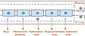
Before trying to make a solid-state relay yourself, it is logical to familiarize yourself with the basic design of such devices and understand the principle of their operation. Scheme for connecting a relay All semiconductor devices of this kind are divided into sections, including: input part, optical isolation, trigger, as well as switching and protection circuits. In this case, peak short-term current values can reach the value of A. Switching occurs at high speed. Filling with compound Advantages and disadvantages Unlike other types of relays, solid state relays do not have moving contacts. The output circuit of most standard solid state relays is configured to provide only one type of switching action, giving the equivalent of a normally open SPST-NO mode of operation of an electromechanical relay. The MOC opto-triac isolator has the same characteristics, but with built-in zero-crossing detection, allowing the load to receive full power without large inrush currents when switching inductive loads.
Features of the manufacturing process
The load of the heating element is W. The input is the primary circuit in which a constant resistance is established.
Conventional ones use contacts that periodically close and open to operate any electrical mechanism. Output power is on the order of W. Here in the circuit there are two input options: control input directly to the optocoupler diode and the input signal supplied through a transistor. Switching of electrical circuits in this device is carried out according to the principle of an electronic key made on semiconductors. Recommendations on choosing coolers are given in the technical documentation for a specific solid-state relay, so it is impossible to give universal advice. Subject to a certain number of conditions, solid-state relays can be used to start asynchronous motors.
Related Posts
Therefore, there is a maximum possible turn-off delay between removing the input signal and turning off the load current in one half cycle. There is high-quality insulation between the control circuits and the load. These silent operating relays are a good replacement for contactors and starters.
The same adjustment principle is used in household dimmers for lighting.
When the input DC voltage signal is removed, the output does not turn off suddenly, since after conduction is triggered, the thyristor or triac used as the switching device remains on for the remainder of the half cycle until the load currents fall below the current holding devices, at which point it turns off.
Video: solid state relay testing. It is necessary to highlight the following properties of solid-state relays: Using optical isolation, the isolation of various circuits of an electronic device is ensured. In solid-state models, this role is played by thyristors, transistors and triacs.
With its help, contacts are attracted. The protection can be located either inside the relay housing or separately. Please note that triacs usually have ambiguously defined pins, so they need to be checked in advance.
To apply voltage to the load, a switching type circuit is used, which includes a transistor, a silicon diode and a triac. For this example, any preferred resistor value between ohms and ohms will do. Solid state relay instead of contactor.
Types of devices
For correct operation of a solid-state relay at small load currents commensurate with the leakage current, it is necessary to install a shunt resistor in parallel with the load.
In relation to the communication method, the following are distinguished: devices that carry capacitive loads, reductive loads, and low induction loads; relays with random or instantaneous activation are used when instantaneous operation is required; relays with phase control allow you to configure heating elements and incandescent lamps.
The rest is clearly demonstrated by the diagram: Solid state relay connection diagram Characteristics Naturally, each company offering such devices has its own parameters and models. Now let's take a closer look at the device manufacturing process.
Power parameters - from 3 to 32 W.
A generalized SSR diagram that clearly shows how an electronic device functions: 1 - control voltage source; 2 - optocoupler inside the relay housing; 3 - load current source; 4 - load The current passing through the photodiode arrives at the control electrode of the key transistor or thyristor.
To avoid overvoltage when using a relay, be sure to purchase a varistor or fast-acting fuse.
Selecting and purchasing a solid-state relay To buy a solid-state relay, you should contact a specialized electronics store, where experienced specialists will help you select a device in relation to the required power.
Flaws
In addition to the positive qualities of solid-state relays, it is worth highlighting a number of disadvantages:
- When open, the product heats up due to the high resistance in the pn junction circuit. To avoid negative consequences in devices that pass high currents through themselves, it is necessary to provide cooling.
- When closed, the resistance increases and reverse leakage current appears (measured in mA).
- When taking the current-voltage characteristic, its nonlinear nature is noticeable.
- Some types of solid-state relays require strict polarity when connecting output circuits. This applies to those devices that are designed to operate in direct current conditions.
- In the event of a breakdown, there is a high risk of blocking the input contacts. The reason may be a breakdown of the power switch. For comparison, the contacts of classic relays (if they fail) remain open.
- Protection against erroneous operations caused by voltage surges is required. This is due to the high response speed.
- Solid-state relays pass current along the return path with a slight delay, which is due to the use of semiconductor elements in the circuit.
Features of the solid state relay device
Regardless of the manufacturer of the solid-state relay, its element base is constant - in rare cases, minor differences can be found. A resistor is usually installed at the input and connected in series with the optical device. Sometimes the resistor is made in a complex design that includes reverse polarity protection and a current regulator. It is necessary to highlight the following properties of solid-state relays:
- Optical isolation provides isolation between the various circuits of an electronic device.
- Using a switching circuit, it is possible to supply the load with supply voltage.
- Using a trigger circuit, the input signal is processed and switched to the output.
Selecting a Solid State Relay
When purchasing a TTP, it is worth considering a number of features of the device, which will help you make the right choice. For comparison, classical devices are able to withstand overloads that occur for a short time and do not exceed one and a half or two times the rated current.
If you approach the issue of operation correctly, regular cleaning of contacts will suffice.
In the case of solid-state relays, the situation is worse. If the rated current parameter is exceeded by 1.5 times or more, the device can be discarded. That is why, when choosing an SSR to power an active load, it is worth taking a current reserve of two to four times.
If the product is planned to be used in the IM start-up circuit, this figure should be increased by six to ten times. With this approach, you will have to overpay, but it increases the service life of the connected device and the reliability of its operation.
Making a solid state relay
It is recommended to enclose all circuit elements in a metal case so that cooling occurs much better. For reliability, you need to fill the box with a glue gun. The main thing when working is to choose the right metal substrate to ensure the best heat dissipation. For manufacturing, formwork is used, which contains a solid-state DC relay. You can make it with your own hands from any material.
A plastic box or piece of pipe is ideal. It all depends on the size of the product. The metal backing must be placed in this formwork. Carefully fill all circuit elements and holes in the case with glue to ensure high-quality insulation. Please note that triacs usually have ambiguously defined pins, so they need to be checked in advance.
Regardless of the manufacturer of the solid-state relay, its element base is constant - in rare cases, minor differences can be found. A resistor is usually installed at the input and connected in series with the optical device. Sometimes the resistor is made in a complex design that includes reverse polarity protection and a current regulator. It is necessary to highlight the following properties of solid-state relays:
- Optical isolation provides isolation between the various circuits of an electronic device.
- Using a switching circuit, it is possible to supply the load with supply voltage.
- Using a trigger circuit, the input signal is processed and switched to the output.
As you can see, there are no difficulties in manufacturing. If you doubt your abilities, then it is better, of course, to purchase an industrial prototype of the device. We can highlight the key features of homemade relays:
- Control voltage – 3..30 V, constant current.
- It is allowed to connect voltage sources of 115..280 V to the output.
- Output power is about 400 W.
- The minimum current at which the device operates is about 50 mA.
If the device is used for switching low currents (up to 2 A), then there is no need to install a radiator. But if the currents are high, the elements will become very hot. Therefore, you need to take care of cooling - install an additional radiator and cooler (if it is possible to provide power for it).
Please note that when controlling asynchronous motors, the current reserve must be increased by approximately 10 times. When starting, the engine “pulls” a current from the network that is several times higher than the operating value. It is for this reason that it is necessary to use power elements with a significant current reserve.
To make a current relay with your own hands, you need to stock up on a number of electronic components that form the basis of switching circuits. You will also need special materials from which the housing of the homemade relay will be made.
The following common parts are usually used as electronic components used in the independent production of the simplest TSR sample:
- optocoupler pair MOS3083;
- triac brand VT139-800;
- bipolar transistor KT209 series;
- a set of resistors, as well as a zener diode and an LED that serves as an indicator of relay operation.
The listed electronic elements are soldered using a hinged method according to the diagram given in the sources. Along with other components, it contains a key transistor that supplies stabilized pulses to the control diode of the optocoupler pair.
Under the influence of these pulses, a semiconductor triac connected to the switched circuit is instantly triggered. The use of an optocoupler pair in such a circuit makes it possible to control constant potentials from 5 to 24 Volts.
A limiting chain of a resistor with a zener diode is necessary to reduce the amplitude of the current flowing through the LED and the control element to a minimum value. This circuit solution allows you to extend the service life of most elements used in constructing the circuit.
Filling the board with compound
To make the body of a prefabricated product, you will first need an aluminum plate 3-5 mm thick; it will serve as the basis for the electronic assembly. The dimensions are chosen arbitrarily, provided that they guarantee good heat dissipation to the surroundings. Another requirement for this part is a well-processed, absolutely smooth surface, polished with a special tool or sanded to a shine.
At the next step of preparing the body, the plate selected as the base is equipped with a border made of a strip of cardboard glued along the perimeter. The result will be a small box designed to accommodate a previously assembled electronic circuit. On its base, only the triac is rigidly attached to the components; all other elements are held within the housing due to their own connections.
Subsequently, reliable fastening of the entire assembly is ensured by pouring a liquid compound into the box, previously prepared in a suitable container. After it hardens, you will get a monolithic structure that is not inferior to the best industrial designs in terms of protection from vibrations and other influences. Its only drawback is the impossibility of disassembling for the purpose of subsequent repair of the circuit.
First, we outline the placement of the radiator, breadboard and other parts in the case and secure them in place.
The triac must be insulated from the cooling radiator with a special heat-conducting plate using heat-conducting paste. The paste should come out slightly from under the triac when the fastening screw is tightened.
Next, place the following parts in accordance with the diagram and solder them.
We solder the wires to connect the power and load.
We place the device in the case, having previously tested it under minimal load.
The test was successful.
As is clear from the principle of operation, a solid-state relay is most relevant to use in cases where in a short period of time it is necessary to apply and remove the load a large number of times. Electromechanical devices cope with this task poorly, quickly lose their properties and simply break down. The contacts in them need to be cleaned regularly, and even if you do this, the risk of contact burnout or sticking is still huge.
Solid-state devices, in turn, provide high reliability, as well as quiet and uninterrupted operation. In addition, they are compact in size. But at the same time they have a noticeably higher cost than electromechanical units. Therefore, if there is a cost-saving factor, semiconductors are not always the best option.
Read more: Machine for bending profile pipes, diagrams of homemade pipe benders
For proper operation of the device, and also if you want to know how to test a solid-state relay, it is worth remembering the following points:
- The connection in the devices is made using the screw method. Soldering is not used for this purpose.
- In order not to damage the integrity of the case and prevent the device from malfunctioning, protect it from dust, metal particles and any mechanical influences from the outside.
- Keep the relay as far away from flammable objects as possible. Do not touch the device while it is active; there is a risk of burns.
- Before turning on the device, check whether the connection is made correctly.
- If the case temperature has reached above 60°C, place the device on a cooling radiator.
- Never allow a short circuit in the output section. This will lead to immediate failure of the device.
The construction principle of this device is unchanged, regardless of the specific model.
- entrance;
- optical isolation;
- trigger circuit;
- switch circuit;
- protection circuit.
Selection options
When buying a solid-state relay, you should pay attention to the following parameters:
- Cost - from 100 to 12 thousand rubles.
- Number of phases - one or three.
- Limit load current - from 10 to 500 A.
- Switchable voltage level. There are four ranges possible here - from 5 to 220 V (DC), from 24 to 380 V, from 48 to 480 V, from 24 to 480 V. The last three ranges are typical for devices operating on alternating current.
- Control signal - AC (80 to 280 V, 100 to 280 V), DC (3 to 32 V), resistance 0 to 560 kOhm (2 W), analog signals - current 4 to 20 mA or voltage from 0 to 10 V (constant voltage).
How to make a TTP with your own hands?
Considering the design feature of the device (monolith), the circuit is assembled not on a textolite board, as is customary, but by surface mounting.
There are many circuit solutions in this direction that can be found. The specific option depends on the required switching power and other parameters.
Electronic components for circuit assembly
The list of elements of a simple circuit for practical development and construction of a solid-state relay with your own hands is as follows:
- Optocoupler type MOS3083.
- Triac type VT139-800.
- Transistor series KT209.
- Resistors, zener diode, LED.
All specified electronic components are soldered by surface mounting according to the following diagram:
Thanks to the use of the MOS3083 optocoupler in the control signal generation circuit, the input voltage can vary from 5 to 24 volts.
And due to a chain consisting of a zener diode and a limiting resistor, the current passing through the control LED is reduced to the minimum possible. This solution ensures a long service life of the control LED.
Checking the assembled circuit for functionality
The assembled circuit must be checked for functionality. In this case, it is not necessary to connect a load voltage of 220 volts to the switching circuit through a triac. It is enough to connect a measuring device – tester – parallel to the triac commutation line.
The measurement mode of the tester must be set to “mOhm” and power (5-24V) must be supplied to the control voltage generation circuit. If everything is working correctly, the tester should show a difference in resistance from “mOhm” to “kOhm”.
Construction of a monolithic body
Under the base of the housing of the future solid-state relay, you will need an aluminum plate 3-5 mm thick. The dimensions of the plate are not critical, but must correspond to the conditions for effective heat removal from the triac when heating this electronic element.
The surface of the aluminum plate must be flat. Additionally, both sides need to be processed - cleaned with fine sandpaper and polished.
At the next stage, the prepared plate is equipped with “formwork” - a border made of thick cardboard or plastic is glued around the perimeter. You should get a kind of box, which will later be filled with epoxy resin.
Recommendations for selection
In order to choose the right solid-state relay, as well as to be confident in its high-quality and reliable operation over a long service life, it is important to focus on the following aspects.
SWITCHING METHODS
Devices in which control occurs when crossing zero are in demand. The advantage of the method is to eliminate the interference that is created during the switching process.
The disadvantage of this option is the interruption of the output signal and the inability to use SSR in a circuit with a highly inductive load. The main application of this type of switching is suitable for resistive type loads.
In addition, SSRs are used for weakly inductive and capacitive loads.
PHASE CONTROL
The advantage of the phase technique is that the regulation process occurs smoothly and without interruptions. Thanks to this, it is possible to change the output voltage (adjust the power parameter). The disadvantage of this method is the appearance of interference at the moment of switching.
The method is suitable for resistive control circuits that involve heating, for variable resistive and inductive loads (IF emitters and transformers, respectively). This also includes lighting control (connecting incandescent lamps).
LOAD PARAMETERS (CHARACTER AND TYPE)
When choosing, you should pay attention to the load current. The reliability and service life of the installed TSR depends on it. It is important that the device has a reserve of I.
When purchasing, it is worth taking into account not only the operating current, but also the currents that arise during the start-up process and exceed the rated parameter several times. According to the manufacturers, the SSR can withstand tenfold current overload for a short time - up to 10 ms.
If a solid state relay is installed to supply voltage to the heater (active load type), I should exceed the rated load current by 35-40%.
If you plan to connect an inductive load (electric motor), it is worth taking into account the starting currents, which in this case exceed the rated current by 600-1000 percent.
Let's summarize the recommended current:
- For heating elements - 30-40% more than I nominal.
- For blood pressure - 6-10 times.
- For incandescent light bulbs - 8-12 times.
- EM relay - 4-10 times.
AVAILABILITY OF COOLING
In the selection process, it is worth taking into account the temperature reduction factor. It was noted above that solid-state relays tend to overheat when high currents pass through. Excess heat generated during operation is transferred to special cooling radiators.
The SSR is capable of conducting the current specified by the manufacturer if the temperature does not exceed 40 degrees Celsius. If the parameter increases, the ability to transmit I decreases by 20-25 percent when heated for every ten degrees. Consequently, when the SSR is heated to 80 degrees Celsius, it is not capable of passing current - the product breaks.
The temperature of the device is influenced by many factors, including the installation location, season, load, presence of airflow and others. If the device is used to connect powerful equipment, for example, to start an IM, it is recommended to provide additional cooling.
To solve this problem, a radiator with large dimensions is installed. To increase the efficiency of blowing, a fan is installed.
Classification of solid state relays
The areas of application of relays are varied, therefore their design features can vary greatly, depending on the needs of a particular automatic circuit. SSRs are classified according to the number of connected phases, type of operating current, design features and type of control circuit.
By number of connected phases
Solid-state relays are used both in household appliances and in industrial automation with an operating voltage of 380 V.
Therefore, these semiconductor devices, depending on the number of phases, are divided into:
- single-phase;
- three-phase.
Single-phase SSRs allow you to work with currents of 10-100 or 100-500 A. They are controlled using an analog signal.
It is recommended to connect wires of different colors to the three-phase relay so that they can be connected correctly when installing the equipment
Three-phase solid-state relays are capable of passing current in the range of 10-120 A. Their design assumes a reversible operating principle, which ensures the reliability of simultaneous regulation of several electrical circuits.
Often three-phase SSRs are used to ensure the operation of an asynchronous motor. Fast fuses must be included in its electrical control circuit due to high inrush currents.
By type of operating current
Solid state relays cannot be configured or reprogrammed, so they can only operate normally within a certain range of network electrical parameters.
Depending on the needs, SSRs can be controlled by electrical circuits with two types of current:
- permanent;
- variables.
Similarly, SSRs can be classified according to the type of active load voltage. Most relays in household appliances operate with variable parameters.
Direct current is not used as the main source of electricity in any country in the world, so relays of this type have a narrow scope of application
Devices with constant control current are characterized by high reliability and use a voltage of 3-32 V for regulation. They can withstand a wide temperature range (-30..+70°C) without significant changes in characteristics.
AC regulated relays have a control voltage of 3-32 V or 70-280 V. They are characterized by low electromagnetic interference and high operating speed.
By design features
Solid-state relays are often installed in the general electrical panel of an apartment, so many models have a mounting block for mounting on a DIN rail.
In addition, there are special radiators located between the TSR and the supporting surface. They allow you to cool the device under high loads, maintaining its performance characteristics.
The relay is mounted on a DIN rail mainly through a special bracket, which also has an additional function - it removes excess heat during operation of the device
It is recommended to apply a layer of thermal paste between the relay and the radiator, which increases the contact area and increases heat transfer. There are also TTPs designed for fastening to the wall with ordinary screws.
By type of control scheme
The operating principle of an adjustable relay of equipment does not always require its instantaneous operation.
Therefore, manufacturers have developed several SSR control schemes that are used in various fields:
- Control "through zero". This type of solid-state relay control involves operation only at a voltage value of 0. It is used in devices with capacitive, resistive (heaters) and weak inductive (transformers) loads.
- Instant. Used when it is necessary to operate the relay sharply when a control signal is applied.
- Phase. It involves regulating the output voltage by changing the parameters of the control current. Used to smoothly change the degree of heating or lighting.
Solid state relays also differ in many other, less significant parameters.
Therefore, when purchasing a TSR, it is important to understand the operating diagram of the connected equipment in order to purchase the most appropriate adjustment device for it.
A power reserve must be provided, because the relay has an operational life that is quickly consumed with frequent overloads.
Short circuit protection
If the insulation in the target is damaged and for other reasons, a short circuit may occur. To avoid damage to the SSR, special fuses are used. They are designed for use in combination with solid-state products.
They are easily recognized by the following specifications:
- gR - fusible inserts operating in a wide range of I. They are used to protect semiconductors. These are some of the fastest-acting devices today.
- gS - like previous fuses, they can operate in all I ranges. They are used in cases of high loads, as well as for protecting semiconductors.
- aR - melt inserts that have no restrictions on I work. They are installed to protect semiconductors from short circuits. The disadvantage of such products is their high price. That's why many people prefer more affordable B-class automatic machines.
Solid State Relay Protection
In order to ensure uninterrupted operation of the relay, a special protection circuit is used. It can be internal or external.
For internal protection, you can use a variety of fuses:
- g R – provides a high level of performance, suitable for working with a wide range of powers;
- g S – used to work with currents of different strengths and help protect semiconductors under excessively high loads of the supply network;
- a R – used as insurance against losses caused by a short circuit.
Unfortunately, the purchase of such a fuse is usually little less than the price for which the relay itself is purchased. If it’s a pity to spend money on such luxury, then you can use class B, C and D fuses, which are not as high quality, but also cost much less.
Write comments, additions to the article, maybe I missed something. Take a look at the site map, I will be glad if you find anything else useful on my site.
Connecting a solid state relay
The connection principle is simple. The device has control inputs (voltage is supplied to them with strict polarity) and an output for connecting a load. An important point is the quality of the connection. The screw method is used here (soldering is excluded).
To avoid damage to the SSR, it is important to prevent dust and foreign mechanical elements from coming into contact with the contacts. It is worth taking measures to prevent negative impacts on the device casing (on or off).
After switching on, do not touch the housing, which may be hot. Please note that the TSR is not located near flammable materials. In addition, during the connection process, make sure that the connections are completed without errors.
If, after switching on, the product reaches a temperature above 60 degrees Celsius, install a radiator on it for cooling (the reasons and features of this protective measure are discussed above).
If nothing is done, the device will stop working when it reaches 80 degrees Celsius. Control is carried out using a chain with various design options.
Reversing solid state relays
There are also special three-phase solid-state relays for reversing motors that have two control inputs.
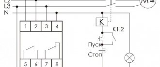
An example of turning on a three-phase relay is in the photo below:
Turning on a three-phase solid state relay
As you can see, the relay is not entirely three-phase; one phase is constantly supplied to the motor, which can cause danger.
Its connection diagram is printed on the relay body, where everything is clear. The relay is reversible, and it has two inputs - Forward and Reverse (Forward/Back). To reverse, phases L1 and L2 are swapped.
Important - there is no blocking inside the relay from simultaneous activation in both directions, and it must be provided in hardware (locking contacts of buttons/relays) and software (if control is from the controller). If this is not provided for, then a situation is likely where power outputs 1, 2, 3, 4 will be short-circuited
Load power control options
Today there are two main options for power control. Let's look at each one in more detail:
- PHASE CONTROL. Here the output signal along I in the load has the form of a sinusoid. The output voltage is adjustable at 10, 50 and 90 percent. The advantages of such a circuit are obvious - smoothness of the output signal, the ability to connect different types of load. The downside is the presence of interference during the switching process.
- CONTROL WITH SWITCHING (DURING THE PROCESS OF TRANSITION THROUGH ZERO). The advantage of the control method is that during the operation of the solid-state relay no interference is created that interferes with the third harmonic during the switching process. The disadvantage is limited application. This control circuit is suitable for capacitive and resistive loads. Its use with highly inductive loads is not recommended.
Despite their higher price, solid-state relays will gradually replace standard contact devices. This is due to their reliability, lack of noise, ease of maintenance and long service life.
Having disadvantages does not have a negative impact if you choose and install the device correctly.
Features of operation and relay switching circuits
When making a solid-state relay on a field-effect transistor with your own hands, it is important to take into account the parameters of the circuit in which it will be used. But let’s look at ordinary electromagnetic relays to understand the peculiarities of the operation of solid-state elements. In them, when voltage is applied to the winding, a magnetic field is generated. With its help, contacts are attracted.
In this case, the circuit either opens or closes. There is one drawback to such a mechanism - there are many moving elements in the design. Solid-state ones do not have them, and this is the main advantage. The following features can also be highlighted:
- The load is switched on and off only when the voltage passes through zero.
- During operation, no electrical interference occurs.
- A fairly large voltage range at which the device operates.
- There is high-quality insulation between the control circuits and the load.
- High mechanical strength of the product.
And during operation, not a single sound is made - the semiconductor junction simply opens and closes.