A lighting control system based on pulse relays can no longer be called some kind of know-how.
She appeared a very long time ago. However, the widespread practice of introducing and using bistable relays, as they are also called scientifically, instead of the old time-tested pass-through switches, is becoming increasingly widespread right now.
Of course, there are more modern devices based on control via a Wi-Fi signal or connected to a PLC, but impulse switches (blocking relays) are more affordable for a wide range of ordinary users.
On average, their price ranges from 1000 - 1500 rubles per piece, depending on the manufacturer and functionality (built-in timer, central control function, etc.)
They are also more repairable. If one relay fails, only one lighting zone will stop working, and the light will not go out in the whole house, as will happen with a PLC.
Let's look at how it all works, what circuits it is connected to, and try to figure out whether it is better or worse than pass-through switches.
Impulse relays or pass-through switches
In long corridors, on stairs when going from the first to the second floor, in bedrooms, it is very convenient to turn on the light at the entrance, and turn it off in a completely different place (at the exit or near the bed).
In such cases, electricians recommend installing pass-through (flight) and cross switches.
What is the significant difference between them and impulse relays? And why does everyone refuse switches?
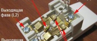
What does the connection diagram look like at the checkpoints? As a rule, power is first supplied to the branch box under the ceiling, and then from it to the switches themselves. For installation, a three-core cable VVGng-Ls 3*1.5mm2 is used.
The more switches you install, the more wires you will need.
When installing pass-through two-key switches, you already have 6 contacts, wires need to be connected to each of them.
Would you like to try connecting such a bundle correctly in a junction box? Not every electrician can immediately figure out such a connection diagram.
In this case, each of the switches passes directly through itself the entire load current. This means that during switching or a short circuit, contact burnout is quite possible.
Another feature of pass-throughs is the absence of a fixed key position. You cannot understand from its state whether the switch is on or off, as is done on a single-keyboard.
This will directly depend on other “brothers” collected in one chain. Which is not always convenient and takes some getting used to.
Several types of connection diagrams
There are several installation options, each of which has its own characteristics, advantages and disadvantages. The designation of the RIO-1 relay contacts has the following meaning:
- N – neutral wire;
- Y1 – enable input;
- Y2 – shutdown input;
- Y – on/off input;
- 11-14 – switching contacts of the normally open type.
These designations are used on most relay models, but before connecting to the circuit you should additionally familiarize yourself with them in the product data sheet.
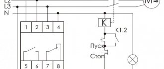
The presented electrification circuit is used to control the light from three places using a relay and three push-button switches without fixing the position
In this circuit, the power relay contacts use a current of 16 A. The control and lighting circuits are protected by a 10 A circuit breaker. Therefore, the wires have a diameter of at least 1.5 mm2.
The connection of push-button switches is made in parallel. The red wire is the phase, it goes through all three push-button switches to power contact 11.
The orange wire is the switching phase, it comes to input Y. After which it leaves terminal 14 and goes to the light bulbs. The neutral wire from the bus is connected to terminal N and to the lamps.
If the light was initially turned on, then when you press any switch the light will go out - a short-term switching of the phase wire to the Y terminal will occur and contacts 11-14 will open.
The same thing will happen the next time you press any other switch. But pins 11-14 will change position and the light will turn on.
The advantage of the above circuit over pass-through and crossover switches is obvious. However, with a short circuit, detecting the damage will cause some difficulties, unlike the next option.
This scheme will save on wires, since the cross-section of control cables can be reduced to 0.5 mm2. However, you will have to purchase a second protection device
This is a less common connection option. It is the same as the previous one, but the control and lighting circuits have their own circuit breakers for 6 and 10 A, respectively. This makes it easier to identify faults.
If there is a need to control several lighting groups with a separate relay, then the circuit is slightly modified.
This connection method is convenient to use to turn lights on and off in entire groups. For example, immediately turn off a multi-level chandelier or the lighting of all workplaces in the workshop
Another option for using impulse relays is a centrally controlled system.
The scheme is convenient because you can turn off all the lighting with one button when leaving home. And when you return, turn it on in the same way
Two switches are added to this circuit to make and break the circuit. The first button can only turn on the lighting group. In this case, the phase from the “ON” switch will come to the Y1 terminals of each relay and contacts 11-14 will close.
The trip switch operates similarly to the first switch. But switching is carried out on the Y2 terminals of each switch and its contacts occupy the circuit-breaking position.
Why only push-button ones?
When using pulse relays, other types of switches are used - push-button, bell or push-type.
Please note that simple single-key or two-key keyboards will not work here.
With rare exceptions, for example for the Meander RIO-2 relay. But more on that later.
Based on this fact, a signal cannot be applied to pulse relays for too long, otherwise its coil will burn out. Some manufacturers warn that the continuous signal time on their models should be no more than 1 minute.
And some children really like to play with such buttons, after which they fail.
Push-button switches resemble ordinary ones in appearance, only inside their design there is a return spring, which after each press returns the key and contact to its original position.
There are also two-key buttons in one housing.
They will come in handy when you want to connect general lighting in the kitchen from one relay and at the same time illumination of the work area of the countertop.
Or in the hall - a chandelier and lighting around the perimeter, plus a separate sconce.
Many people use spring-loaded buttons for doorbells instead of special switches.
Types, labeling and benefits
The main types of pulse relays are electromechanical and electronic. Electromechanical, in turn, are classified according to their operating principle.
Types of pulse devices
This means that switching of power contacts can be carried out by forces other than the force of the magnet. They are divided into:
- electromagnetic;
- induction;
- magnetoelectric;
- electrodynamic.
Electromagnetic devices in automation systems are used more often than others. They are quite reliable due to a simple method of operation based on the action of electromagnetic forces in a ferromagnetic core, provided that there is current in the coil.
The impact on the contacts here is carried out by a frame, which in one position is attracted by the core, and in the second is returned by a spring.
The armature, i.e. a plate with magnetic properties, is attracted by an electromagnet, which is a copper wire wound on a coil with a yoke
Induction ones have a principle of operation based on the contact of alternating currents with induced magnetic fluxes with the fluxes themselves.
This interaction creates a torque that moves a copper disk located between two electromagnets. Rotating, it closes and opens contacts.
The operation of magnetoelectric devices is carried out due to the interaction of the current in the rotating frame with the magnetic field created by a permanent magnet. The closing/breaking of contacts is controlled by its rotation.
These relays are very sensitive relative to their type. However, they are not widely used due to the response time of 0.1-0.2 s, which is considered long.
Electrodynamic relays operate due to the force generated between moving and fixed current coils. The method of closing contacts is the same as in a magnetoelectric device. The only difference is that induction in the working gap is created electromagnetically.
Electronic models are almost identical in design to electromechanical ones. They have the same blocks: executing, intermediate and control.
The only difference is the latter. Switching is controlled by a semiconductor diode as part of a microcontroller on a printed circuit board.
Transistors and thyristors act as semiconductors in this device. Although they can withstand harsh dust and vibration conditions, they are susceptible to short current and voltage overloads
This type of relay is equipped with additional modules. For example, a timer allows you to run a lighting control program after a specified period of time.
This is convenient for saving energy when there is no need to operate the equipment. If necessary, you can turn off the light by pressing the button twice.
Advantages and disadvantages of the main types of relays
Unlike semiconductor switches, electromechanical switches have the following advantages:
- Relatively low cost due to inexpensive components.
- A small amount of heat is generated at the switched contacts due to the low voltage drop.
- The presence of powerful insulation of 5 kV between the coil and the contact group.
- Not subject to the harmful effects of overvoltage pulses, interference from lightning, or switching processes of powerful electrical installations.
- Control of lines with a load of up to 0.4 kV with a small device volume.
When a circuit is closed with a current of 10 A in a small volume relay, less than 0.5 W is distributed across the coil. While on electronic analogues this figure can be more than 15 W. Thanks to this, there is no problem of cooling and harm to the atmosphere.
Their disadvantages include:
- Wear and problems when switching inductive loads and high voltages with direct current.
- Turning the circuit on and off is accompanied by the generation of radio interference. This requires installing shielding or increasing the distance to the equipment subject to interference.
- Relatively long response time.
Another disadvantage is the presence of continuous mechanical and electrical wear during switching. These include oxidation of contacts and their damage from spark discharges, deformation of spring blocks.
During installation, it is worth considering that the electromechanical version of the contactors may not work correctly if it is in a horizontal position
Unlike electromechanical relays, electronic relays control the intermediate unit via a microcontroller.
The advantages and disadvantages of electronics can be analyzed using the example of devices from the F&F company relative to the ABB brand, which produces mechanics.
The advantages of the first type of switches include:
- greater security;
- high switching speed;
- availability on the market;
- indicator alerts about the operating mode;
- advanced functionality;
- silent operation.
In addition, the indisputable advantage lies in several installation options - it is possible to install not only on the DIN rail of the panel, but also in a socket box.
Disadvantages of F&F electronics compared to ABB mechanics:
- disruption of work due to power failures;
- overheating when switching high currents;
- “glitches” are possible for no apparent reason;
- switching off the device during a short-term power outage;
- high resistance in closed position;
- some relays only operate on DC current;
- The semiconductor circuit does not immediately allow current to flow back to its normal direction.
Despite these shortcomings, electronic switches are constantly evolving and, due to the greater potential of functionality relative to electromechanical ones, their predominant use is expected.
To avoid confusion, the manufacturer provides the most detailed product characteristics in the store catalogs and in the technical data sheet of the device
Main characterizing parameters
Depending on the purpose and area of application, relays can be classified according to several criteria:
- return coefficient - the ratio of the value of the armature output current to the retraction current;
- output current – its maximum value in the coil terminals when the armature exits;
- retraction current - its minimum indicator in the coil clamps when the armature returns to its original position;
- setting – the level of the response value within specified limits, set in the relay;
- response value – the value of the input signal to which the device automatically responds;
- nominal values - voltage, current and other quantities underlying the operation of the relay.
Electromagnetic devices can also be divided by response time. The longest delay for a time relay is more than 1 second, with the ability to configure this parameter.
Then there are slow ones - 0.15 seconds, normal ones - 0.05 seconds, fast ones - 0.05 seconds. And the fastest inertia-free ones are less than 0.001 seconds.
Decoding product labeling
The contactor marking code can often be found in store catalogs and on the device itself. It gives a complete description of the design features, purpose and conditions of their use.
The composition of the designation can be seen on the electromagnetic intermediate relay REP-26. It is used in AC circuits up to 380 V and DC up to 220 V.
To understand the markings, you need to break the inscription into blocks and use descriptive tables that can be found in specialized reference books
The product designation in the store may look like this: REP 26-004A526042-40UHL4.
REP 26 – ХХХ Х Х ХХ ХХ Х – 40ХХХ4. This type of notation can be parsed as follows:
- 26 – series number;
- XXX – type of contacts and their number;
- X – wear resistance class of switching;
- X – type of switching coil, type of relay return and type of current;
- XX – design according to the method of installation and connection of conductors;
- ХХ – coil current or voltage value;
- X – additional structural elements;
- 40 – protection level according to IP standard or GOST 14254;
- ХХХ4 – climatic zone of application in accordance with GOST 15150.
Climatic design can be: UHL - for cold and temperate climates or O - for tropical or general climate design.
According to special designation tables, the device in question is an intermediate electromagnetic relay, with four switching contacts, switching resistance class A, using direct current.
It has a socket mount with lamellas for soldering external conductors, a 24 V coil and a manual manipulator.
Comparison of circuits using pass-through switches and pulse relays
The most important advantage of all these relays is that the buttons are connected to each other in parallel and a two-wire wire is enough for this.
Regardless of how many buttons you use - two, three, four, etc.
This significantly saves cable costs and simplifies lighting connections.
Visually compare the diagram and number of wires in the same room when installing pass-through switches and impulse relays.
Scheme on pass-through switches
Scheme on a pulse relay
As you can see, in the second case there is at least double savings (two-core cable instead of four-core, fewer connections, more free space in junction boxes). The functionality of the lighting in the room was not affected at all by this.
Device
There is a wide variety of pulse relays on the market; due to technical and design differences, you can find different devices. But as an example, we will consider the simplest and most practical principle of operation for understanding (see Figure 1).
Rice. 1. Example of a pulse relay device
The simplest example of a pulse relay consists of the following elements:
- Coil - made of a copper conductor wound on a non-magnetic base, for example, a frame made of textolite, electrical cardboard, etc. Designed to create an electromagnetic field that affects magnetic elements.
- The core is made of ferromagnetic materials that interact with the magnetic field of the coil. Designed to move and perform magnetic influence.
- Relay contact system - consists of movable and fixed contacts designed to transmit a signal.
- Resistive, capacitive and signal elements are used to set the operating logic of the device and indicate the state.
- Timer – sets the time interval for the relay, but is not present in all models; it helps to significantly expand the functionality of the equipment.
How to connect a pulse relay
To correctly connect a pulse relay, you need to understand what contacts it has and what they are responsible for.
Typically this is:
- two contacts per power coil A1-A2
On one of them, phase or zero constantly arrives, and on the other, an impulse is given after pressing the button.
- power contacts 1-2, 3-4, etc.
Passing through them, the current flows to the lamp.
Here is the simplest diagram for connecting one pulse relay to a group of push-button switches.
Scheme No. 1
Please note that in a pulse relay the load does not pass through the button at all. By pressing it, you just give an impulse to the coil, which closes the power contact.
In some models, a control pulse can be supplied both through the phase conductor and through the neutral conductor.
Imagine that a significant and extensive part of the electrical wiring in your house will not even be constantly energized, as is the case with conventional light switches. How much this will improve fire and electrical safety!
Some varieties have several contacts at once. You can connect two, three or more lighting groups from them.
Passing the entire load through the relay means that burning or burnout of the contacts on the buttons is virtually impossible. Many, rejoicing at this circumstance, boldly lower the cross-section of the lighting lines to 0.5mm2 or 0.75mm2. Or they simply “throw away” the twisted pair cable.
However, do not forget about the rules, which clearly state that all group lines to lamps in residential premises must be carried out with conductors with a cross-section of at least 1.5 mm2.
Please note that all relays (group or single) must be connected after the machine.
He protects:
- reel
- control cable
- the lamp itself
Without it, in the event of a short circuit, your electrical wiring will simply burn out.
The relay itself does not protect against overloads or short circuits.
Therefore, when assembling the circuit in the panel, you seem to “hang” one or more pulse relays on each lighting circuit breaker.
Useful designs from a conventional relay
Greetings, Samodelkins! Today we’ll talk about a regular electromagnetic relay. A simple relay, not very durable and seemingly unremarkable. The author of the YouTube channel “AKA KASYAN” will tell you where and for what purposes it can be used and what simple but very useful structures can be assembled on its basis. By the way, this material is tailored for the beginning radio amateur. Well, let's get started.
Our first scheme
built on the basis of a relay and an electrolytic capacitor.
In order to understand what it is intended for, first let's understand how the whole thing works. Power, for example, 12V through the power contact of the relay is supplied to the positive plate of the capacitor and at the same time to the coil. Minus or ground power is supplied directly, bypassing the contacts.
Initially, before power is applied, the indicated relay contacts are closed.
As soon as power is supplied, the relay is triggered, contacts 1 and 2 open, and instead contacts 1 and 3 close. But by that time, enough energy has accumulated in our capacitor, and it is the energy stored in the capacitor that powers the coil. As long as the voltage across the capacitor is sufficient to power the relay coil, the contacts will be in this state.
Over time, due to the discharge of the capacitor, the solenoid within the relay becomes unable to maintain the contacts in this state. The relay turns off and the contacts return to their original state. The capacitor is charged again, the relay is activated and the process is repeated again, that is, the relay periodically changes its state, then on, then off.
The on/off intervals depend solely on the capacitance of the capacitor. The larger the capacitance, the longer the solenoid will hold contacts and vice versa. There are several ways to connect the load to our breaker: 1) through a break in one of the power wires;
2) use the 3rd relay contact;
3) use a relay with 2 contact groups.
The first 2 options have several disadvantages. Firstly, high power loads cannot be connected and, secondly, these decisions will affect the operating frequency of the circuit. The third option is the most correct, since the contacts that will switch the load are in no way connected with the control contacts, which makes it possible to connect any loads, including network ones, to the circuit. The power of the connected load depends solely on the capacity of the relay, that is, on the current allowed through its contacts. This parameter is indicated on the relay body, as is the solenoid voltage.
This circuit, like all subsequent ones, is so simple that there is no point in making it on a printed circuit board.
And so, if you are into electronics and want your homemade products to look like a factory product, then you can order a board from the Chinese. The second scheme is a little more complicated.
Here, in addition to the capacitor, 2 more components are added - a resistor and a transistor.
Almost any transistor, low or medium power, reverse conductivity. This circuit is a turn-on delay system, something like a time relay. When power is applied to the circuit, the relay does not turn on immediately, but after some time. At the initial moment, the capacitor is slowly charged through a limiting resistor.
As soon as the voltage on this capacitor reaches a certain value (about 0.6-0.7V), the transistor is activated. Through its open transition, power is supplied to the relay winding. The relay is activated, switching the load.
The delay time depends on the capacitance of the capacitor and the resistance of the resistor.
The greater the capacitance and resistance, the greater the delay and vice versa. The following diagram:
It may seem that the author forgot to draw some components, but to assemble this design we don’t need anything else besides the relay. The principle of operation is the same as that of the first scheme. Power is supplied to the solenoid through the closed contact, it is activated, the contacts open, the power supply stops, and since the solenoid is de-energized, the contacts return to their original state.
Such a converter is practically uncontrollable. Operation occurs with a fairly high frequency and it must be said that standard relays will not last long in this mode. But there is still a meaning to this scheme. The fact is that inductive loads are characterized by the phenomenon of self-induction, and our solenoid is precisely an inductance. What's the catch? At the moment when power is supplied to the solenoid, it seems to accumulate some energy. When the supply circuit opens, the solenoid releases the accumulated energy, while the self-induction EMF is much higher than the supply voltage.
Even when powered by a 9-volt Krona battery, the self-induction voltage of the solenoid reaches several tens or even hundreds of volts.
But don’t be afraid, it’s not dangerous, but getting an unpleasant electric shock is still possible. If we add a rectifying diode and a storage capacitor to our circuit, we get something similar to a stun gun.
Everything is simple here. The breaker provides periodic power supply to the solenoid; after turning off the power, the self-induction voltage through the rectifier accumulates in the capacitor. A capacitor is definitely needed for 250 or 400V. Due to the small capacitance, a few seconds of operation of the circuit is enough for the capacitor to charge.
The energy accumulated in a capacitor can perform a useful action, or not entirely useful. Of course, such a thing cannot be used as a shocker, but it hits quite unpleasantly. An interesting version of a photo relay can be built using just two components: a photoresistor and a relay.
Photo relays that can be found on the network, even the simplest versions, contain a transistor and a pair of resistors.
This is correct, such schemes are more practical, but the presented option also has a right to life. A photoresistor is the most common; its resistance in the dark is very high; in daylight it drops to several hundred Ohms.
The operating principle is as follows. During the day, when it is light, the resistance of the photoresistor is minimal and the relay is activated, opening contacts 1 and 2. The load, for example a lamp, is turned off. With the arrival of darkness, the resistance of the photoresistor begins to increase, therefore the current in the relay coil decreases, and at some point the current will not be enough, and the relay contacts will turn off. In this case, contacts 1 and 2 will close, and the load (the same light bulb) will work, illuminating the courtyard or path.
The disadvantage of this circuit, unlike those that include at least 1 control transistor, is that this option does not have the ability to be adjusted.
This material has been prepared for informational purposes only.
It's time to wrap this up. Thank you for attention. See you again!
Video:
Source
Become the author of the site, publish your own articles, descriptions of homemade products and pay for the text. Read more here.
Centralized lighting control with one button
On models with so-called central or centralized control, in addition to the above, there are additional ON and OFF terminals.
When voltage is applied to them, the relay is forced to either turn off (OFF) or turn on (ON).
They are used when assembling a circuit with a master button or master switch. That is, when leaving the house, with just one button you can centrally turn off the lights on all floors and in all rooms.
Here is a circuit assembled into several group lamps connected from different impulse relays. Please note that in this case all relays must be centrally controlled, otherwise the circuit will not work.
Scheme No. 2 - with central control
For ABB pulse generators, the central control unit can be purchased separately and connected to the left side of the E290 relay.
Just be extremely careful when assembling such a control circuit in a three-phase 380V switchboard.
If there is a three-phase system, some lighting groups are powered from different phases in order to evenly distribute the load.
In this case, it is impossible to connect all the OFF and ON contacts on the switches with jumpers, as is often done in single-phase panels. You will have to transfer all control circuits to a separate machine and it is from it that you will supply the phase of the same name to turn on and off all pulse relays simultaneously.
And then, this is possible when using electromechanical models. For electronic ones, you will have to decouple through intermediate relays.
Relay operation in non-standard situations
Many people wonder what will happen to the relay when the voltage in the house disappears and then reappears? Wouldn't all the lights turn on at once in this case? No, that won't happen.
However, the pin position status will vary depending on the specific model. Whether they have memory or not. If the memory is present, the previously turned on lights will light up again. Where there is no memory, the contacts will simply open.
What happens if two people press two buttons at the same time? This will be perceived as a one-time click. That is, the light will either light up or go out, depending on its previous position.
The pulse relay for installation in an electrical panel has the form factor of a modular contactor and is mounted on a DIN rail. The rated current of most models is 10-16A.
This is quite enough to organize lighting in an apartment or country house.
If you want to connect a more powerful load, then you will have to use a starter in the circuit, or choose models with higher currents.
Pulse relay for installation in a distribution box
In addition to panel-mounted options, there are also mounted ones, for installation behind a suspended ceiling or directly into a distribution box.
With their help, you can organize the switching of lighting in your apartment from single-key switches to pulse switches. You replace the switches in the wiring boxes with buttons and switch the wires in the junction box.
This is what this diagram looks like when connecting a pulse relay directly in the distribution box under the ceiling.
Scheme No. 3
In this case, little changes in your electrical panel, and you get an excellent lighting control option, similar to pass-through switches.
When connecting several lamps at once from a standard impulse switch in a switchboard room, rather than just one light bulb, be sure to install a cross-module or terminal blocks.
It is unlikely that it will be possible to run two or three cables per relay (the limitation on the thickness of the wire will not allow it). You'll have to scatter them across different pads.
Photo relay
A typical application for a photo relay is turning on the lighting when it gets dark and turning it off when the light level is sufficient. Despite the triviality of such a task, its implementation has a number of nuances that are usually not taken into account in the simplest devices from Asian manufacturers.
The Finder photo relay line is represented by two series of devices - devices with integrated light sensors ( series 10 ) for mounting on a wall or ceiling (Figure 1), and series 11, which requires placement on a standard DIN rail, as well as operation with an external photocell. Series 10, while losing to the 11th in functionality, is certainly easier to install and generally somewhat cheaper.
Rice. 1. Series 10 photo relay 12…16 A
The basic functionality of integrated wall-mounted photo relays (models 10.32, 10.41, 10.42 and 10.51 ) involves flexible adjustment of the response threshold in the range from 1 to 80 lux. In this case, relay 10.42 assumes setting an individual illumination level for each of the 16 A outputs. This solution makes it possible to create, for example, two-level illumination - minimal at dusk and full at nightfall.
The Finder 10.61 has a fixed switching threshold of 10 lux, but is distinguished by its compact dimensions, comparable to the dimensions of a conventional light sensor. This device is designed for ceiling mounting and is an excellent solution for a budget lighting control system.
Relays 10.32, 10.41 and 10.51 have a patented “light compensation” function (Figure 2). The essence of this technology is that it prevents the possibility of incorrect operation of the relay, when the photocell perceives the lighting it turns on and sends a signal to open the contacts. This effect is characterized by periodic turning on and off of the lighting and is often a sign of improper installation of the sensor. Finder photo relays recalculate the set switch-off threshold, so in most cases they are not susceptible to such a “disease”.
Rice. 2. Light compensation technology
Even the simplest Finder photo relays of the 11 series (Figure 3) have better characteristics than the line of integrated devices. Among the obvious advantages is an expanded sensitivity range: up to 100 lux in junior models and up to 1000 lux in the most advanced devices 11.41, 11.42 and 11.91, equipped with a four-position switch. These photo relays support normal and high sensitivity ranges, as well as "always on" and "always off" modes. The latter is convenient for turning off the night lighting system, for example, if the owner of the house leaves.
Rice. 3. Series 11 photo relay 12…16 A
Let us separately dwell on the “zero hysteresis” technology used in photo relay 11.41 (Figure 4). Most standard relays, in order to prevent incorrect operation, have a hysteresis that leads to a delay in turning off the lighting. The Finder relay has no such drawback and is triggered at a precisely specified light threshold, preventing unnecessary energy consumption.
Rice. 4. Operating principle of the zero hysteresis circuit
A few words about the flagship of the Finder photo relay line - model 11.91. It combines the capabilities of a time relay and a multifunctional photo relay. The device can be programmed to turn on and off, which allows you to implement complex system operation algorithms. Example: automatic switching on of lighting according to the light level and its complete shutdown from midnight to 5 am.
Types of pulse relays
What other types of pulse relays exist? For example, there is a time delay function.
It can be used to delay both when the light is turned on and when it is turned off. You leave your own cottage in the evening and press a special button in the house.
This gives you time to calmly walk along the illuminated paths to the gate and only after that the light will automatically turn off.
This method does not even require the installation of separate switches on the street.
You can also connect an exhaust fan in the bathroom to such relays. When leaving the bathroom, you press the button, and the fan continues to run for the period of time you set.
Device and principle of operation
In the general sense of the word, a relay is an electrical mechanism that closes or breaks an electrical circuit based on certain electrical or other parameters that influence it.
Its non-switching design was invented back in 1831 by J. Henry. And two years later they began to use S. Morse to ensure the functioning of the telegraph.
Two main groups can be distinguished: electromechanical and electronic. In the first type of device, the work is carried out by a mechanism, and in the second, a printed circuit board with a microcontroller is responsible for everything. It is convenient to consider its operation using the example of an electromechanical relay, which is a pulse relay.
When choosing a relay operating mode, you must be guided by the frequency of switching on, the type and magnitude of the current, and the nature of the loads being tested.
Structurally, it can be represented as follows:
- A coil is a copper wire wound around a base of non-magnetic material. It can be insulated with fabric or coated with varnish that does not allow electricity to pass through.
- A core containing iron and activated by the passage of electric current through the turns of a coil.
- A movable armature is a plate that is attached to the armature and exerts an influence on the closing contacts.
- The contact system is a direct circuit state switch.
The operation of a relay is based on the phenomenon of electromagnetic force. It appears in the ferromagnetic core of the coil when current is passed through it.
The coil in this case is a retractor device. The core in it is connected to a movable armature, which activates the power contacts, carrying out switching. They can be of normally open/normally closed type.
Sometimes a contact block may contain both open and closed types of connection.
When the circuit is turned on, the mechanism fixes this position, which changes when the pulse is applied again and is fixed again until the next change
An additional resistor can be connected to the coil, which increases the accuracy of operation, as well as a semiconductor diode, which limits the overvoltage on the winding.
In addition, the design may contain a capacitor installed parallel to the contacts to reduce sparking.
The operation of the device can be more clearly represented by dividing it into several blocks:
- the performer is a contact group that closes/opens the electrical circuit;
- intermediate - the coil, core and moving armature activate the executing unit;
- control - in this relay converts an electrical signal into a magnetic field.
Since a single electrical impulse is required to switch the position of the contacts, we can conclude that these devices consume voltage only at the moment of switching. This significantly saves energy, unlike conventional pass-through switches.
The second type of pulse relay is the electronic type. The microcontroller is responsible for its operation.
The intermediate block here is a coil or semiconductor switch. The use of elements such as programmable logic controllers in the circuit makes it possible to supplement the relay, for example, with a timer.
This type of device has no mechanical moving elements. The work is carried out by a sensor that recognizes the control signal and solid-state electronics that switches the circuit