An electrical device such as a photo relay for street lighting provides sufficient visibility at night. In this case, the light sensor is triggered automatically and does not require mechanical activation. This device saves energy and is easy to use. In today's review we will look at the advantages and disadvantages of photo relays, types and connection diagrams that are used in practice. Along the way, we’ll tell you how to make and configure the device yourself.
Photo relay for street lighting
What is a photo relay for street lighting and why is it needed?
Photo sensors are designed to automatically illuminate various sections of the street when it gets dark. Many people know that in the past, lights on poles were turned on by special services. Now, thanks to light sensors, this process is carried out without human intervention.
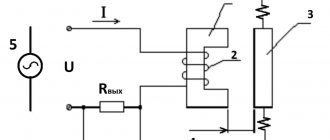
A visual diagram of connecting a photosensor for street lighting
A conventional photosensor contains a sensitive sensor that reacts to daylight, and the electrical circuit of the device in this case is isolated. When darkness sets in, the device, on the contrary, acts as a conductor. For this reason, at night it is active, ensures that the lamp turns on for illumination, and in the morning, when a light flux hits it, the circuit is turned off.
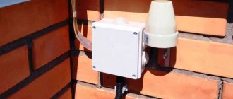
Photocell with mounting device
An outdoor street lamp with a light sensor contains a control circuit, which is placed in the device body. To connect the device to the electrical power system, conductors are removed from it. Typically, the photocell is installed using a bracket in the place where the sun's rays will hit it.
Technical characteristics of photo relay for street lighting
Any photo relay has certain technical characteristics, according to which you can select it for specific tasks:
Supply voltage. In most cases, photo relays are designed to operate in 220 V networks with a frequency of 50 Hz.
- Maximum load current. This is a very important indicator, which indicates how much power the load can be switched by the photo relay. The more powerful the load, the greater the current should be. Typically this parameter is in the range from 5 to 16 A.
- The manufacturer may indicate different load currents at different cosϕ values if a reactive load is connected. Fluorescent lamps are a reactive load and this must be taken into account when choosing a photo relay.
- Trigger threshold at a certain level of illumination. Most photo relays have an adjustable response threshold in the range from 5 to 50 lux (lux). The adjustment is made using a special potentiometer.
- Internal power consumption when activated - how much power the photo relay consumes when the relay is activated. Typically it ranges from 5 to 10 W.
- Own power consumption in standby mode. In modern photo relays it is extremely small - 0.1-1 W.
- Appearance of Photo Relay Delay from short-term darkening. Most photo relays are equipped with a special delay circuit that avoids false alarms. The time interval is usually from 15 to 30 seconds. Shell protection degree.
- There is an international system for classifying the degree of protection of the shell from the penetration of solid objects and water - Ingress Protection Rating. Considering that most photo relays are installed outdoors, it is better to purchase one with a degree of protection of at least IP44. Operating temperature range. The larger it is, the better. A good photo relay should operate in the range from -20 to +50°C.
- Types of photo relays for street lighting According to the location of the light sensor, photo relays can be: With a built-in light sensor mounted in the device body. With remote light sensor. Such photo relays are usually installed in electrical panels on a DIN rail, and the sensor is located outside and connected using a cable. A photo relay can be combined in the same housing with a motion sensor; more about it here. Then only in the dark, if there is a moving object in the field of view of the device, will the sensor trigger and turn on the lighting.
It will be interesting➡ Time relay: what is it and where is it used
Photo relays may have a threshold control and most of these smart devices do. Very rarely, but there are models that do not have adjustment. Naturally, when choosing, the most preferable ones should be photo relays with the ability to adjust. Some photo relays may have a built-in timer that allows you to set the time interval during which the photo relay is allowed to operate. Outside this period, the lighting will not turn on. Some models have a switch on the body that allows you to force the lighting to turn on or off regardless of the time of day, which can be useful in some cases. For example, if you need to turn off the lighting altogether for a certain period, you do not need to disconnect the wires from the terminals of the device.
Advantages and disadvantages of using photo relays for street lighting
To ensure the necessary level of visibility in the courtyard of the house and not worry about constantly turning on and off electrical equipment, you should install a simple street lamp with a light sensor. The photocell device has a small control board and housing, so it does not take up much space and is light in weight. For this reason, the sensor can be installed on almost any surface.
Thanks to the device, significant energy savings are achieved, since its consumption is much less. Also, the advantages of using a photocell include:
- operation of the device at low currents;
- high response speed, in comparison with mechanical analogues;
- greater device performance;
- absence of mechanical contacts (which eliminates rapid wear of equipment);
- long period of operation.
Along with the advantages of light sensors, it is worth talking about the existing disadvantages. First of all, it is necessary to carefully check the device case during purchase for leaks. If it is missing, moisture may penetrate inside the case and cause oxidation of the contacts.
Hermetically sealed twilight photo sensor housing
It is also necessary to ensure that the device does not melt during operation and does not have mechanical damage.
Expert opinion
Vitaly Panfilov
SS, OS, ACS design engineer (communication systems, security and fire alarms, access control system) ASP North-West LLC
Ask a specialist
“A dirty photo sensor housing prevents the normal penetration of light rays. For this reason, the device must always be kept clean.”
Light sensor device: what is the principle of operation of the photo relay based on
Before connecting a lamp with a photocell for street lighting, you need to understand the operating principle of the sensor itself. Let's look at the functionality of the device using the FR-7 photo relay as an example.
Photo relay model FR-7
When darkness sets in, a group of contacts located inside the sensor housing closes. They include lighting fixtures that are in a single circuit. As soon as the level of daylight is “restored”, the contacts open and the lamps turn off.
Table 1. Determination of illumination level using photocells
| Image | Item name | Function description |
| Phototransistor | The device is designed to adjust the output signal when natural light hits the sensitive element | |
| Light-emitting diode | The sensitive element of the LED device is activated under the influence of sunlight according to the principle of the photovoltaic effect | |
| Phototriac | The device functions as a current synchronizer and transmits them to the working electrodes | |
| Photothyristor | The luminous flux, hitting the sensitive element of the device, transfers a charge, which is converted into a signal using a special matrix |
Please note that the vast majority of sensors (for example, photo relay FR-2) have a certain shutter speed - a time interval. It is necessary to prevent devices from triggering due to false signals. For this reason, you should avoid installing light sensors near artificial sources.
Connection diagram of classic photo relays to the consumption line
All types of commercially produced or self-made relays require separate power. Accordingly, two contacts of the device will be intended for the named purposes. Moreover, there are photo relay models without a built-in voltage converter, which means that power is supplied to them not from a 220 V network, but through a separate step-down unit. There may be several lines going to consumers, depending on the number of internal electromagnetic switches. Moreover, the input can be separate for each contact, combined among others, or even integrated with the power supply of the photo relay itself.
The light sensor in most models is built into the body of the device itself, but there are also separate options that allow you to move it away from the device itself. The latter is necessary in cases where the photodetector is not illuminated by controlled lamps, so that the system does not turn into a strobe. That is, when it is dark, the device turns on the lamps. It becomes light - he turns them off. Again it triggers darkness. And so on in a circle.
Single
The previously described model FR-602 and similar ones are connected to the line as follows:
For a large number of energy consumers
To control a powerful load, for example, when connecting a spotlight or numerous lamps, it is better to use intermediate relays. In the role of the latter, appropriate devices are selected that can withstand the passage of a large current sufficient for power supply. An example would be RK-1p/2p (Un), MRP-2, IEK ORM-41F-1, DEKraft PR-102 and the like. Please note that some of the relays of a similar design are designed to control alternating current (AC), while others are designed to control direct current (DC). In addition, the switching voltage may differ to the lower side from the socket rating. The last two factors are important to consider when designing a wiring diagram. If the intermediary relay is powered by direct current, then the photo relay must control the supply of electricity to the conversion unit. Which, once turned on, will activate the electromagnetic contactor, activating the main power line of client devices.
Using other photo relay models
Here is a diagram for connecting a photo relay for another version of the finite state machine - with an external light sensitivity sensor and separate contact lines. Initially it was prepared for FR-7E, but is also suitable for similar models from other manufacturers.
Photo of FR-07E:
Please note that the presented photo relay and the one mentioned earlier differ in the housing, and in particular in the protection of the device from external factors. The FR-601/602 can be safely placed outdoors on the street, while the FR-7E requires the installation of an additional casing for a similar effect. But devices of a similar installation plan are produced with all the necessary fastenings in a standard electrical panel, including prepared mounting locations for the DIN rail.
Main technical characteristics of light sensors for street lighting
The photo relay is capable of providing fully automatic control of lighting fixtures outside the house and on the street. To choose it correctly, it is necessary to take into account the technical characteristics. Each device is designed for uninterrupted operation with a certain voltage. If you want to buy a photo relay for street lighting that will be used for domestic purposes, you should choose models designed for 220 V.
Technical characteristics on the photo relay body
The current characteristics of devices must be taken into account, since if the amperage is incorrectly calculated, the photorelay will quickly fail. To do this, it is necessary to divide the sum of all external lighting devices by the network voltage. The result should not exceed the value specified by the manufacturer.
In addition, it is extremely important to consider what the load on the electrical network will be, the difference in operating temperatures and power consumption. The home owner can choose a light sensor model with a built-in timer. Such devices are very simple and easy to use. With their help, you can set time intervals when the photo relay will operate. There are also devices with programming capabilities, which allows you to fine-tune for a long period of time (monthly up to a year).
What are the main types of photo relays?
A conventional light sensor is triggered by the intensity of sunlight. It allows you to turn lights on and off. There are also combined models that have a complex structure and wide functionality.
Table 2. Types of photo relays
| Item Image | Device type | Features, functions |
| Combined photocell with timer | The device makes it possible to temporarily configure the relay operation. The light will burn strictly on time, which ensures high savings in energy consumption | |
| Light relay with motion sensor | The photo relay turns on the lighting device only in case of movement. When it stops, the light goes out, which also contributes to significant savings. This device is very convenient to use because it does not require any human intervention. | |
| Programmable sensors | The device allows you to use various combinations of settings (temporary, seasonal, motion triggered, etc.) | |
| Combined photocells with time settings and light switching on when moving | Relays are a type of programmable sensor that allows you to make time settings and turn on lights according to specific needs. |
Astro timer - what is it?
It is equally important to know how to connect a time relay for lighting so that it works flawlessly. It is known that different regions have their own time zones. Therefore, if in one city it works strictly according to the specified parameters, in another an error will appear in the form of incorrect operation (for example, it will turn on before the specified value).
Astronomical timer
Since sunrises and sunsets are cyclical processes, the astronomical timer controller has special firmware with time data. The device calculates data daily, which determines the frequency of turning on and off the lighting equipment.
Choosing the right place to install the photocell to turn on the light
In order for a street lamp with a photo relay to work properly, you must choose the right place for its installation. First of all, you need to know that the sensor should be located where it will be well illuminated by the rays of the Sun during the periods of sunrise and sunset.
Installing a photo relay in an open space
If the photocell is installed near the road, care must be taken to ensure that it is not exposed to the headlights of passing vehicles. It is also necessary to carry out installation work in such a way that it is convenient to reach the sensor if necessary. As practice shows, it is quite difficult to install a photo relay correctly. To do this, you need to move it in the intended mounting area to achieve the desired effect.
Choosing an installation location
For the photo relay to work correctly, it is important to choose its location correctly. Several factors need to be taken into account:
- Sunlight should fall on it, that is, it should be in the open air.
- The nearest sources of artificial light (windows, lamps, lanterns, etc.) should be located as far away as possible.
- It is not advisable for headlights to shine on it.
- It is advisable to place it not very high - for ease of maintenance (you must periodically wipe the surface from dust and brush off snow).
In order for photosensitive machines to work correctly, you need to choose the right location
As you can see, when organizing automatic lighting on the street, choosing a place to install a photo relay is not the easiest task. Sometimes you have to move it several times until you find an acceptable position. Often, if a light sensor is used to turn on a lamp on a pole, they try to place the photo relay there. This is completely unnecessary and very inconvenient - you have to clear off dust or snow quite often and climbing a pole every time is not very fun. The photo relay itself can be placed on the wall of the house, for example, and the power cable can be connected to the lamp. This is the most convenient option.
Possible connection diagrams for photo relays for street lighting
The simplest diagram for connecting a light sensor
Connecting a photo relay for a street lighting system is quite simple. The element must be powered and the phase wire (interrupted inside the device) must be brought out to the consumer - to the lamp. The neutral cable must be connected to the input contact of the photocell and the load itself.
Wiring diagram for connecting a lighting system with a sensor
For safe use, photo relays and lighting systems must be connected using a junction box with a sealed housing. The simplest light sensor connection schemes should be avoided, as they are unreliable. Using a relay, it is possible to control any lighting equipment, including powerful spotlights. Most of them have a choke in their design, so it is necessary to include a contactor in the electrical circuit. Thus, the power of the sensor will be enough to control the starter device, which, in turn, supplies voltage to the lamps.
Connection diagrams
The connection diagram of a photo relay for street lighting is simple: a phase and a zero are supplied to the input of the device, from the output the phase is supplied to the load (lights), and the zero (minus) to the load comes from the machine or from the bus.
Connection diagram for photo relay for lighting (lantern)
If you do everything according to the rules, the connection of wires must be done in a distribution box (junction box). Choose a sealed model for outdoor location and install it in an accessible place. How to connect a photo relay to street lighting in this case is shown in the diagram below.
Connecting a photosensor via a junction box
If you need to turn on/off a powerful lamp on a pole, the design of which has a choke, it is better to add a starter (contactor) to the circuit. It is designed for frequent switching on and off and can withstand inrush currents normally.
Connection diagram of a day-night sensor with a starter
If the light should be turned on only while a person is there (in an outdoor toilet, near a gate), a motion sensor is added to the photo relay. In such a combination, it is better to first install a light-sensitive switch, and after it a motion sensor. With this design, the motion sensor will only trigger in the dark.
Connection diagram for photo relay with motion sensor
As you can see, the schemes are simple, you can easily do it yourself.
How to connect a light sensor for street lighting yourself
Outdoor light sensor for turning on lights with built-in power unit
Let's consider a way to connect a light sensor with a power unit to a street lamp. A simple night-day relay is installed near lighting equipment. Manufacturers of such devices provide instructions with a detailed description of the stages of work and diagrams. Typically, relays are installed directly on lamp posts. In this case, the height is selected up to 3 m.
Connecting a light sensor via a machine
Connecting a photo relay with an external sensor
The remote light sensor is mounted in a similar way. The photo relay must be fixed in a certain place so that a sufficient amount of sunlight falls on it; the unit is connected in the room where the electrical panel is installed.
Remote sensors with control unit
Step-by-step instructions for connecting a photo relay in the video:
Connecting a photo relay
Unfortunately, there is no uniform standard for connecting photo relays, and each manufacturer offers its own method. But in general, they are practically indistinguishable, and the main problem if you decide to connect a photo relay with your own hands may be a relay with an external photocell.
Therefore, in our article we will consider almost all possible connection options.
Connecting a photo relay with a built-in power unit
Connecting a photo relay with a built-in power unit
- The simplest photo relays with a built-in power unit usually have three outputs. Of which, phase wires will be connected to two terminals, and neutral wires will be connected to the third. The connection of a protective conductor is usually not provided.
- To connect, first of all, remove the voltage from the section of the circuit where the work is to be done.
- After this, we connect the phase wire coming from the supply circuit breaker to pin “L1” (other pin markings may be applied).
- To terminal “L2” we connect the phase wire to which our lighting devices are connected.
- We connect the neutral wire to terminal “N”. It is necessary so that the photocell for turning on the lighting can work normally.
- Now, after making all the necessary adjustments, you can apply voltage and test our photo relay.
Connecting a photo relay with an external photocell
Connecting a photo relay with an external photocell
A special feature of a photo relay with a remote element is that the sensor itself is located separately from the power unit. The photocell for turning on the lighting is connected separately; therefore, such power units have five terminals.
- To connect such a photo relay, you must first connect the power wires. This is done exactly like connecting a photo relay with a built-in power unit.
Note! Some power units with a remote sensor have the ability to connect several different lighting groups at once. In this regard, such blocks will have four or more phase outputs. The connection is made to any two paired outputs.
- After this we can directly connect the photocells to turn on the lighting. To do this, we have two pins that are marked accordingly. This marking varies greatly between manufacturers, but in most cases it depicts the sensor.
- After making all the necessary settings, we can apply voltage and test the performance of our circuit.
How to set up a light sensor for street lighting yourself
It is advisable to choose a photo relay with the ability to independently adjust various parameters. Most models have the appropriate mechanical devices necessary to set the light sensitivity threshold.
Adjusting light sensitivity on the sensor
If you do not know how to connect a photo relay and adjust it, there are special indicators on the device body. If you turn the regulator upward, the relay will turn on the flashlight as soon as it starts to get a little dark outside, and vice versa.
Photo relay without housing
How to set up a photo relay for street lighting
The setup procedure allows you to adjust the sensitivity of the device and set the desired response threshold under certain conditions. The setting should be performed after connecting the photo relay and connecting all the wires. If you turn the device over, on the bottom side you can find a plastic regulator in the form of a rotary disk. Nearby there are arrows showing in which direction you need to turn to increase or decrease the sensitivity of the photo relay. Typically, turning clockwise increases the parameter, and turning the knob counterclockwise decreases it.
Is it possible to make a photo relay for street lighting with your own hands?
Approximate assembly diagram of a photo relay with a motion sensor.
In practice, the photo relay circuit is assembled quite simply with your own hands. To prevent the device from becoming bulky, it is not recommended to use too many structural elements. For example, an emitter follower should be assembled from two transistors, which are designed to amplify the input signal.
Visual assembly of a photo relay
It is also necessary to use a low-power relay in the circuit, which will serve as a transistor cascade. To create a barrier against the effects of reverse currents, it is recommended to use diodes. As the voltage increases, the device becomes more sensitive to light flux.
Areas of rational application of photo relays
Typical situations in which the presence of this device is required:
- When turning a circuit on and off is done using a low power signal;
- When several circuits must be controlled by a single signal.
The effectiveness of using photo relays is also determined by their versatility (in addition to standard control equipment, you can use computers or laptops). This also makes it possible to implement logical control commands such as “if...then...”.
Consider the use of photo relays for street lighting. The technology of their application is based on the use of trigger FET switches.
Block diagram of photo relay with FET switch
The block diagram below uses the K series of MOS transistors. Unlike solid state relays, the circuit drives photodiodes directly. This allows for much faster switching speeds since the power-off time when the LED is turned on is not critical. Due to the lack of mechanical components, the device is highly compact, but there is no physical isolation barrier, and therefore only a low-voltage control signal must be used.
Since the photo relay is an alternative to an existing remote lighting control panel, the first thing to think about is whether such a replacement is really necessary. If the existing system is fully compliant with electrical codes, simply adding a relay panel before the load will provide full control of the lighting circuit. Up to 64 photo relays can be placed in a small housing along with a low voltage source, and a breaker panel can be placed nearby. The fewer the number of circuits, the more economical the use of a relay panel becomes.
The photo relay can be used to control single-pole 127/220 VAC circuits and two-pole (208...240 V) AC circuits. Relay panels are most economical when controlling smaller loads, but have one drawback - they are designed for a limited number of on/off cycles: from 20,000 to 50,000 (under normal circumstances, this will last about 5 years).
A general view of the block layout of a photo relay for street lighting and a wiring diagram are shown in the following figures.
There are some nuances in using photo relays in conjunction with motion sensors. As a rule, street lights are turned on all night. But at night, street lights are not needed if there is no traffic. Therefore, they are increasingly using schemes that turn on street lights only when the vehicle is moving and for some time after it. An AVR 8051 microcontroller and several pairs (the more the better) of infrared (IR) sensors are used.
Connecting a relay lighting control panel
The proposed system consists of Atmega8 microcontroller, LDR, PIR sensor and RTC. This system controls street lighting using a light dependent resistor and an IR sensor.
Street lights turn on depending on the intensity of the luminous flux that is perceived by the LDR. If such intensity on photoresistors is low, their resistance value is high. As the overall illumination decreases, this value increases, and thus determines when the street lights should turn on.
At night there is minimal traffic. This circumstance can be used to configure the controller. When peak time arrives, when there is no traffic, the photo relay will turn off the outdoor lighting. When a single vehicle appears, the IR sensor will send a control signal to the microcontroller. He will turn on the lighting for 2...3 minutes, after which he will automatically turn it off.
Block layout of photo relay
Scheme for switching on a photo relay for controlling outdoor lighting
Installation of motion sensors
Wiring diagram for motion control based on photo relay
Review of photo relay models: prices and manufacturers
The products are known to consumers for their high quality products and long warranty period. For street lighting, you should consider the photo relay model FR-601. The device is equipped with a built-in twilight sensor (turns on the lamp in the evening, turns off at dawn).
Twilight photo relay FR-601
The device is wall-mounted and operates from a household network with a maximum voltage of up to 230 V. Protection level is IP-44, AC frequency is 50 Hz. Designed for currents of 6 and 10A. The selling price of the product is 247 rubles.
It is also worth paying attention to the FR-602 photo relay with a built-in sensor. The device can withstand currents up to 20A, the recommended network frequency is up to 60 Hz. A special feature of the device is the ability to adjust the illumination threshold in the range of 5−50 Lux. You can purchase the sensor for 352 rubles.