Electric motors are simple and reliable machines, but they also have some disadvantages that make them difficult to use. In particular, when starting, such devices have high current consumption and, without special devices, start with a jerk due to a mismatch between the engine torque and the load on its shaft. Additional devices that ensure smooth engine operation during startup and reduce starting currents are called soft starters.
What is a soft starter
A soft starter (soft starter) is an electrical device that is used in the operation of asynchronous motors and allows you to monitor and control its startup and parameters for safe operation in an alternating current network. This device reduces the impact of a number of negative factors on the engine, including reducing the likelihood of increased engine heating, eliminating jerking, ensuring smooth starting and reaching the workload. Also, soft starters reduce the negative impact on the electrical network by reducing the starting currents of the electric motor.
Electrical engineers and people involved in the operation of electric motors often call soft starters “soft starters.” This is due to the fact that in English (and most high-quality devices are imported) these devices are called “soft starter” , which means “soft starter”.
Smooth starting of electric motors using frequency converters and soft starters allows you to solve a large number of problems and control the operation of the electric motor within a wide range of its parameters. Particularly often, soft starters are used when working under conditions of heavy starting (with high inertia or starting under load with four times the starting currents, with engine acceleration for at least 30 seconds) and especially difficult starting (with six or eight times the values of starting currents and a long engine acceleration time).
General information about AMR
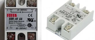
Modern soft starters provide not only a gradual increase in current load, but also a number of other useful functions: monitoring the parameters of the connected electric motor, changing stopping conditions, protective shutdown in case of overload, and much more. Structurally, the soft starter consists of semiconductor elements that can switch to an open or closed state, limiting the load. Additionally, they can be equipped with power contacts, displays, releases and other components.
The use of soft starters for electric motors must be used in the following situations:
- In the presence of powerful electrical machines, especially three-phase asynchronous ones, characterized by high currents. For them, normal operation will be accompanied by false alarms, a noticeable voltage drop and other troubles that affect the normal operation of adjacent devices.
- If technological operations do not allow jerky movements. For example, direct start of a conveyor can lead to a breakdown or stop of production, both at the start and during the braking stage.
- Overload of electrical networks in which currents already exceed rated conditions. At the moment of starting asynchronous motors, annealing of wires, overheating of transformers, or activation of automation at transformer substations and transformer substations may occur.
- Prolonged direct start time, which further complicates the engine acceleration process.
If at least one of the factors is present in your networks, you will need a soft start device, on which the reliability and stability of the entire system will depend. A striking example is the launch of a rolling machine; the diagram of such a control unit is shown below:
Rice. 1. Application of soft starter
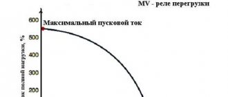
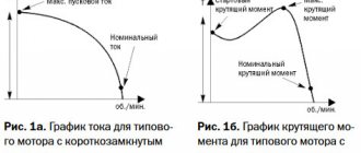
A soft starter is installed in front of an electrical machine to control the current in the motor windings. As you can see from the current and frequency diagram below, the frequency increases gradually, just as the current creates several surges, but not more than the limit set on the soft starter.
The choice of such a responsible unit should be made among trusted manufacturers.
Principle of operation
The main disadvantage of asynchronous electric motors is that the moment of force on the shaft is proportional to the square of the voltage applied to the electric motor. This creates strong jerks during startup and at the moment of stopping operation, which also increases the values of the induction current.
Soft starters can be mechanical and electrical, as well as combined, combining the positive features of both devices.
Mechanical soft starters operate on the principle of counteracting a sharp increase in electric motor speed by influencing its rotor mechanically using brake pads, various clutches, counterweights, magnetic locks and other mechanisms. Such mechanisms have not been used often lately, since there are more advanced electrical control devices.
Electric soft starters gradually increase the current or voltage from the reference level to the maximum, which allows you to smoothly increase the speed of the electric motor and reduce loads and starting currents. Most often, electrical soft starters are controlled electronically using computer systems or electronic devices, which allows you to change starting parameters and control dynamic characteristics. Soft starters allow you to change the operating modes of the electric motor depending on the applied load and allow you to realize one or another relationship between the shaft rotation speed and voltage.
Why was a soft engine start needed?
So, the problem is that the boiler room has pumps for feeding the boiler with water. There are only two pumps, and they are turned on by command from the system for monitoring the water level in the boiler. Only one pump can operate at a time; the pump is selected by the boiler room operator by switching the water taps and electrical switches.
The pumps are driven by conventional asynchronous motors. 7.5 kW asynchronous motors are switched on through conventional contactors (magnetic starters). And since the power is high, the start-up is very hard. Every time you start, there is a noticeable water hammer. The engines themselves, the pumps, and the hydraulic system deteriorate. Sometimes it feels like the pipes and taps are about to shatter into pieces.
In addition, when the boiler has cooled down and hot water is suddenly supplied to it (more than 95 ° C), then unpleasant phenomena occur, reminiscent of explosive seething. It happens the other way around, water with a temperature of 100 °C can be cold - when there is dry steam in the boiler with a temperature of almost 200 °C. In this case, harmful water hammer also occurs.
There are two identical boilers in the boiler room, but the second one has frequency converters for pumps. Boilers (more precisely, steam generators) produce steam with a temperature of more than 115 ° C and a pressure of up to 14 kgf/cm2.
It is a pity that the design of the boiler in the electrical circuit did not provide for smooth activation of the pump motors. Although the boilers are Italian, it was decided to save money on this...
I repeat that to smoothly switch on asynchronous motors we have the following options to choose from:
- star-delta circuit
- smooth start system (soft start)
- frequency converter (inverter)
In this case, it was necessary to choose the option that would require minimal intervention in the operating boiler control circuit.
The fact is that any changes in the operation of the boiler must be agreed upon with the boiler manufacturer (or a certified organization) and with the supervisory organization. Therefore, changes must be made quietly and without unnecessary noise. Although, I don’t interfere with the security system, so it’s not so strict here.
My regular readers know that now, after passing the exams at Rostekhnadzor, I have every right to perform instrumentation and automation work in the boiler room.
Connection diagram of the electric motor to the soft starter
In order to connect the soft starter to the electric motor and the supply network, you should follow the instructions for this type of device; all important aspects of the connection will be indicated there: the circuit sequence, grounding and neutral terminals, as well as the correct adjustment of starting, acceleration and braking. But in general, there are standard connection methods that are suitable for most soft starters.
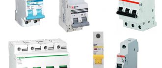
Each soft starter has contacts at the input and the same number at the output for connecting phases, a start and stop control system (START, STOP buttons), other buttons and control contacts. Power cables are connected to the device to the input terminals (usually designated L1, L2, L3), and an electric motor is connected from the output terminals (designated T1, T2, T3). In this case, it is important to connect the soft starter to the network through an input circuit breaker and use cables with a rated cross-section corresponding to the limit value of the motor current when connecting the motor to the soft starter and the soft starter itself to the network.
Power section
The power part includes:
- Input circuit breaker QF
- Power thyristors (not shown in the diagram, located inside the soft starter)
- Bypass (bypass) contactor KM
- Asynchronous electric motor M
- Bypass contactor coil power supply circuit (FU fuse and internal relay contacts 01 and 02)
The voltage to the input power contacts L1, L2, L3 and to the contacts of the KM bypass contactor is supplied through the QF circuit breaker, which is also used to protect the soft starter in the event of an overload or internal short circuit. The rated current of the switch is selected in accordance with the current consumption of the softstarter.
The KM bypass contactor is turned on when the engine reaches maximum speed (when the internal thyristors of the soft starter are fully open). Voltage to the contactor coil is supplied through special output contacts 01 and 02. The diagram shows that power is supplied to the switching through fuse FU from phase L3. When the contacts are closed (full voltage output), phase L3 is supplied to the lower terminal of the KM contactor coil according to the diagram. The upper terminal can be powered by phase L1 (at a voltage of the contactor coil of 380V), or can be connected to the neutral wire N (at a voltage of 220V).
The contactor coil can be supplied with any voltage, for example 24V DC. To do this, you need an appropriate power source, which will be switched through contacts 01 and 02 of the soft starter. In this case, there is no need to connect to phase L3 via fuse FU. A table for selecting a contactor depending on engine power is given in the instructions for a specific model.
The lower contacts of the bypass contactor in the diagram should be connected only to the corresponding softstarter terminals A2, B2, C2, since when the bypass mode is turned on and the engine reaches full power, the engine current is monitored in order to protect it from overload.
The electric motor is connected through the output power terminals T1, T2, T3 through a cable of the appropriate cross-section.
Why is the starting current of an electric motor dangerous?
When voltage is applied to the stator winding, the rotor rotation speed is zero. The rotor must be moved and spun to the rated speed. This requires significantly more energy than what is needed for the nominal operating mode.
Under load, inrush currents are higher than at idle. The mechanical resistance to rotation from the mechanism driven by the engine is added to the weight of the rotor. In practice, they try to minimize the influence of this factor. For example, for powerful fans, the dampers in the air ducts automatically close at the time of startup.
At the moment the starting current flows from the network, significant power is consumed to bring the electric motor to its nominal operating mode. The more powerful the electric motor, the more power it needs to accelerate. Not all electrical networks tolerate this regime without consequences.
Overloading the supply lines inevitably leads to a decrease in network voltage. This not only makes starting the electric motors even more difficult, but also affects other consumers.
And the electric motors themselves experience increased mechanical and electrical loads during startup processes. Mechanical ones are associated with an increase in torque on the shaft. Electrical ones, associated with a short-term increase in current, affect the insulation of the stator and rotor windings, contact connections and starting equipment.
Polarity Balance
The disadvantage of 2-phase control in the soft starter of an asynchronous motor is manifested in the appearance of direct current caused by phase cutoff and superposition of phase currents, which causes strong acoustic noise emitted by the electric motor.
The use of the “polarity balance” method significantly reduces the influence of direct current values during engine acceleration, and the acoustic start-up characteristic is correspondingly reduced, this is achieved by balancing half-waves of different polarities during engine acceleration.
Device interface
The interface of the soft starter soft starter "man-machine" allows you to configure parameters, significantly facilitating and simplifying the process of starting and operating the engine. The built-in pump control function prevents water hammer.
Fig3. Soft starter interface
Rice. B. AS-Interface application module
Fig. 4. Soft start device for an electric motor - diagram of a feeder combination with an AS-interface
The interface consists of two displays with segment indicators and an LCD display, allowing visibility at a considerable distance, and includes a description of parameters and messages.
The hardware capabilities include programming mode selection and language options. Copies parameters from one device to another, increasing programming speed, increasing equipment reliability and gaining the ability to adjust and enter identical parameters on identical machines.
