Power cables with impregnated paper insulation (with viscous impregnation) have significant restrictions on rated voltage due to intense ionization processes at alternating voltage, and therefore are used in distribution networks in Russia at voltages up to 35 kV inclusive (abroad at voltages up to 60 kV).
In Russia, power cables with impregnated paper insulation for voltages up to 35 kV inclusive are produced in accordance with GOST 18410-73
(manufacturers - plants Kamkabel, Sevkabel, Irkutskkabel, Moskabel, etc.). As already noted, these cables are the most popular type of product. Their share is about 95% of all types of cables used in distribution networks.
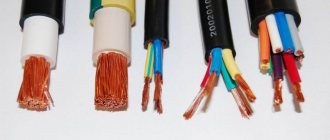
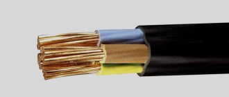
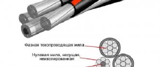
Cables with viscous impregnation for voltages up to 10 kV inclusive (see Fig. 1) are most often made of three-core with belt insulation and sector copper or aluminum conductors with a cross- section from 6 to 240 mm2 or more (cables of the brands AAG, AAShv, ASB, ASShv, SB , SBShv, etc.). Aluminum conductors can be single-wire in the entire range of sections or multi-wire compacted in the range of sections from 70 to 240 mm2. Copper conductors are mainly made as stranded wires.
Cable SBShv
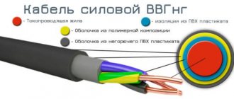
Rice. 1. Structural elements of cables with belt insulation for voltages up to 10 kV:
- The core is single-wire or multi-wire, aluminum or copper;
- Phase paper insulation impregnated with a viscous or non-drip compound;
- Filling from paper bundles;
- Belt paper insulation impregnated with a viscous or non-drip compound;
- Screen made of electrically conductive paper for cables for voltages of 6 kV and more;
- Aluminum or lead sheath.
- Cushion made of bitumen and crepe paper;
- Armor made of steel strips;
- Sublayer of bitumen and PET film;
- Outer cover made of PVC plastic.
Cable insulation consists of cable paper tapes based on sulphate cellulose with a thickness of 80, 120 and 170 microns, impregnated with oil rosin composition. To produce the impregnating composition, cable oil or a mixture of petroleum oils is used. Rosin, polyethylene wax or polyisobutylene are used as a thickener. Each phase of the cables is insulated separately, and then a common so-called belt insulation is applied over the twisted insulated cores.
In cables for voltages of 6 kV and higher, a screen made of semiconducting paper is applied to the belt insulation. The gaps between the insulated conductors in the cable are filled with bundles of sulphate paper.
In cables for voltages of 1 and 3 kV, the insulation thickness is selected mainly based on the condition of its mechanical strength.
For cables with a voltage of 1 kV, the thickness of the phase insulation is 0.75–0.95 mm , and the thickness of the belt insulation is 0.5–0.6 mm , for cables of 3 kV – 1.35 and 0.7 mm , respectively.
In cables for voltages of 6 and 10 kV, the insulation thickness is selected taking into account the electric field strengths in the insulation in operating and emergency modes (for example, a short circuit of one phase to the shell). For 6 kV cables, the thickness of the phase and belt insulation is 2.0 and 0.95 mm, and for 10 kV cables – 2.75 and 1.25 mm, respectively.
The main disadvantage of impregnated paper insulation is its high hygroscopicity.
To protect the insulation from moisture during storage, installation and operation, the cables are enclosed in a lead or aluminum sheath. Recently, most cables are made in an aluminum sheath, because... aluminum shells are quite tight, mechanically stronger and more resistant to vibration loads compared to lead shells. However, cables with aluminum sheaths cannot be used when exposed to aggressive environments.
For an interesting video about paper-insulated cable, see below:
Metal shells, as a rule, are protected from corrosion and mechanical damage by protective covers. The protective cover of cables consists of a cushion, armor and outer cover. The cushion protects the metal shell from corrosion and also plays the role of protection against mechanical damage when applying armor.
The armor can be made of steel strips and galvanized steel round or flat wires.
The simplest design of the outer cover consists of alternating layers of bituminous composition or bitumen, impregnated cable yarn or glass yarn, bitumen composition and a coating that protects the cable turns from sticking together on the drum (for example, a chalk coating).
Power cables with impregnated paper insulation
Power cable is used to transmit electrical energy from the place of its transformation or production to transport and utility facilities, industrial enterprises, stationary power and lighting installations. “Power cable” refers mainly to paper-insulated cables impregnated with a viscous insulating compound for voltages up to 35 kV.
For cables designed for higher voltages, a power cable with excess oil pressure (oil-filled power cable) is used. More widely used are power cables for voltages up to 10 kV, containing three copper or (less commonly) aluminum conductors of a sector shape with a cross-section of up to 240 mm2. The insulation of this cable consists of paper tapes, impregnated with a viscous insulating compound, spirally applied to each core. The insulated cores are covered with belt paper insulation, the thickness of which is approximately half that of the phase insulation. A sealed metal sheath made of lead or aluminum is applied over the belt insulation of the power cable by pressing, and a protective cover is placed on top or without it.
Power cable with impregnated paper insulation for voltages of 20 and 35 kV has round-shaped cores with phase insulation up to 9 mm thick; each lived in a separate metal shell or in a screen made of metal foil.
At temperatures from 50°C to 80°C, the viscosity of the oil-rosin composition decreases; therefore, the upper sections of the power cable on inclined sections of the laying route may become unusable due to the gradual drainage of liquid insulation. Therefore, the maximum permissible height difference between the upper and lower points of the route is strictly limited (from 5 to 25 m for power cables with voltages from 1 to 35 kV, respectively).
Power cable with paper insulation and non-draining impregnating composition is used when laying on routes with steeply inclined and vertical sections, as well as when transitioning from paper insulation to polymer (polyvinyl chloride, polyethylene).
| AAB2L-1 | |
| AAB2L-10 | SB2L |
| AAB2L-6 | SB2LG |
| AAB2LShV-1 | SB2LShV-1 |
| AAB2LShV-10 | SB2LShV-10 |
| AAB2LShV-6 | SB2LShV-6 |
| AAB2LSHP-1 | SBVng-LS-10 |
| AAB2LSHP-10 | SBVng-LS-6 |
| AAB2LSHP-6 | SBG |
| AABV-10 | SBL |
| AABV-6 | SBLG |
| AABVG-10 | SBLSHV-1 |
| AABVG-6 | SBLSHV-10 |
| AABL-1 | SBLSHV-6 |
| AABL-10 | SBNLSHNG-10 |
| AABL-6 | SBSHV-1 |
| AABLG-1 | SBSHV-10 |
| AABLG-10 | SBSHV-6 |
| AABLG-6 | SBSHNG-1 |
| AABLGE-110 | SBSHNG-6 |
| AABLSHNG-6 | SG-1 |
| AABLE-110 | SG-10 |
| AABNLG-1 | SG-20 |
| AABNLG-10 | SG-35 |
| AABNLG-6 | SG-6 |
| AAG-1 | SKL-1 |
| AAG-10 | SKL-10 |
| AAG-20 | SKL-6 |
| AAG-35 | SP-1 |
| AAG-6 | SP-10 |
| AAP2L-1 | SP-6 |
| AAP2L-10 | SP2L-1 |
| AAP2L-6 | SP2L-10 |
| AAP2LShV-1 | SP2L-6 |
| AAP2LShV-10 | LNG-1 |
| AAP2LShV-6 | LNG-10 |
| AAPL-1 | LNG-6 |
| AAPL-10 | SPL-1 |
| AAPL-6 | SPL-10 |
| AAPLG-1 | SPL-6 |
| AAPLG-10 | SSHV-1 |
| AAPLG-6 | SSHV-10 |
| AASHV-1 | SSHV-6 |
| AASHV-10 | TsAAB2L-10 |
| AASHV-6 | TsAAB2L-6 |
| AASHVE-110 | CAABV-10 |
| AASHNG-1 | CAABV-6 |
| AASHNG-10 | TsAABVG-10 |
| AASHNG-6 | TsAABVG-6 |
| AASP-1 | TsAABL-10 |
| AASHP-10 | TsAABL-6 |
| AASHP-35 | TsAABLG-10 |
| AASP-6 | TsAABLG-6 |
| AOSB-20 | TsAABNLG-10 |
| AOSB-35 | TsAABNLG-6 |
| AOSBG-20 | TsAAP2L-10 |
| AOSBG-35 | TsAAP2L-6 |
| AOSK-20 | TsAAPL-10 |
| AOSK-35 | TsAAPL-6 |
| ASB-1 | TsAAPLG-10 |
| ASB-10 | TsAAPLG-6 |
| ASB-6 | CAASHV-10 |
| ASB2L | CAASHV-6 |
| ASB2LG | TSAASHNG-10 |
| ASBLG | TSAASHNG-6 |
| ASB2LShV-1 | TsAOSB-35 |
| ASB2LShV-10 | TsAOSBG-35 |
| ASB2LShV-6 | TsASB-10 |
| ASBVNG-LS-10 | TsASB-6 |
| ASBVNG-LS-6 | TsASB2L-10 |
| ASBG | TsASB2L-6 |
| ASBGE-110 | TsASBG-10 |
| ASBL | TsASBG-6 |
| ASBLSHV-1 | TsASBL-10 |
| ASBLSHV-10 | TsASBL-6 |
| ASBLSHV-6 | TsASBLSHV-10 |
| ASBNLSHNG-10 | TsASBLSHV-6 |
| ASBNLSHNG-6 | TsASBNLSHNG-10 |
| ASBSHV-1 | TsASBNLSHNG-6 |
| ASBSHV-10 | TsASBShV-10 |
| ASBSHV-6 | TsASBSHV-6 |
| ASBE-110 | TsASKL-10 |
| ASG | TsASKL-6 |
| ASKL-1 | TsASKLSHNG-10 |
| ASKL-10 | TSASKLSHNG-6 |
| ASKL-6 | TsASP-10 |
| ASKLShv | CASP-6 |
| ASP-1 | TsASPG-10 |
| ASP-10 | TsASPG-6 |
| ASP-6 | TsASPL-10 |
| ASP2L-1 | TsASPL-6 |
| ASP2L-10 | TsASPLSHNG-10 |
| ASP2L-6 | TsASSHV-10 |
| ASPG-1 | TsASSHV-35 |
| ASPG-10 | TsASSHV-6 |
| ASPG-6 | TsOSB-35 |
| ASPL-1 | TsOSBG-35 |
| ASPL-10 | TsSB-10 |
| ASPL-6 | TsSB-6 |
| ASSHV-1 | TsSB2L-10 |
| ASSHV-10 | TsSB2L-6 |
| ASSHV-6 | TsSBVng-LS-10 |
| ASSHVE-110 | TsSBVng-LS-6 |
| OSB-20 | TsSBG-10 |
| OSB-35 | TsSBG-6 |
| OSBG-20 | CSBL-10 |
| OSBG-35 | TsSBL-6 |
| OSK-20 | TsSBLShV-10 |
| OSK-35 | TsSBLShV-6 |
| TsSBNLSHNG-10 | |
| TsSBSHV-10 | |
| TsSBSHV-6 | |
| TsSBSHV-6 with a cross section of 240 | |
| TsSBSHNG-6 | |
| CSKL-10 | |
| CSKL-6 | |
| TsSKLSHNG-6 | |
| TsSP-10 | |
| TsSP-6 | |
| TsSPG-10 | |
| TsSPG-6 | |
| TsSPL-10 | |
| TsSPL-6 | |
| TsSPLSHNG-10 | |
| TsSPLSHNG-6 | |
| TsSPSHNG-6 | |
| TsSShV-10 | |
| TsSShV-35 | |
| TsSShV-6 |
Covers type Shv and Shp
The most reliable are external covers of the Shv and Shp types , which have the following design:
- adhesive composition based on bitumen,
- plastic tape
- pressed polyvinyl chloride or plastic hose.
To lay cables in rooms or places with an increased fire hazard, the bitumen layers are replaced with a special non-flammable composition (such outer coverings are indicated by the index “ng” in the cable grade, for example cable brand AAShng ). Outer covers of reduced flammability with reduced smoke and gas emissions are also used (indicated by the index “ng-LS” in the cable grade). The choice of the type of protective cover is determined by the material of the cable sheath, as well as the conditions of its installation.
Cables for voltages of 20 and 35 kV are manufactured either in a single-core version with round aluminum and copper conductors in a lead and aluminum sheath (cables of the AAG, ASG, SG, AAShv brands), or in a three-core version (see Fig. 2), while the cable twisted from three round insulated conductors, each of which is enclosed in a lead sheath (cables of the AOSB, OSB, etc. brands).
Cables with separately leaded conductors are produced with round copper and aluminum conductors with a cross-section from 25 to 400 mm2 for 20 kV cables and a cross-section from 120 to 400 mm2 for 35 kV cables . For cables of this type, multi-wire compacted cores are mainly used. To equalize the electric field, screens made of semiconducting paper are placed on the surface of the core. A screen of semiconducting paper, or metallized semiconducting paper, or semiconducting paper and aluminum or copper foil is also placed over the insulation.
AOSB cable
Rice. 2. Structural elements of cables with separately leaded conductors for voltages of 20 and 35 kV:
- The core is stranded, aluminum or copper;
- Screen made of electrically conductive paper;
- Phase paper insulation impregnated with a viscous or non-drip compound;
- Screen made of electrically conductive paper;
- Lead sheath.
- Protective layer of crepe paper and polyethylene terephthalate film;
- Cable yarn filling;
- Cable yarn pillow;
- Armor made of steel strips;
This group includes power cables with aluminum conductors with paper insulation, impregnated with a viscous or non-drip composition, in an aluminum or lead sheath, with or without protective covers, intended for the transmission and distribution of electricity in stationary installations in electrical networks for voltages up to 35 kV alternating current with a frequency of 50 Hz or in direct current electrical networks at ambient temperatures from -50°C to +50°C. Power cables must comply with the requirements of GOST 18410-73. 1. Single-wire or multi-wire copper or aluminum conductor 2. Impregnated phase paper insulation 3. Impregnated paper belt insulation 4. Lead sheath 5. Cushion 6. Armor made of steel tapes or wires (Cl) 7. Outer cover (for cables type B, B2l , Bl) Common types of aluminum power cable with impregnated paper insulation:
- AAB2l - for operation in macroclimatic areas with moderate and cold climates, for operation in the ground (trenches) with low and medium corrosive activity with the presence of stray currents, and with medium and high corrosive activity with the absence of stray currents, if the cables are not exposed during operation tensile forces;
- AABlG - for operation in the open air, in dry rooms, in damp, partially flooded rooms with weak, medium and high corrosive activity, as well as channels, cable mezzanines, mines, collectors, industrial premises, on technological overpasses and on bridges, if available danger of mechanical damage during operation;
- ASB - for laying in the ground (trenches) with low corrosive activity on routes with or without stray currents and in the ground (trenches) with average corrosive activity on routes with the absence of stray currents, if they are not subjected to tensile forces during operation;
- ASBL - for laying in the ground with medium and high levels of soil corrosion activity, with or without stray currents, the cable is characterized by high resistance to bending, thanks to the protective braiding, the cable does not propagate combustion and can be used in fire hazardous areas and explosive areas;
- ASB2l - for laying in the ground (trenches) with moderate corrosive activity on routes with the presence of stray currents and in the ground (trenches) with high corrosive activity on routes with or without stray currents, if they are not subjected to tensile forces during operation;
- ASBG - for cold and tropical climates; if there is a danger of mechanical damage, they are used in the air, in explosive zones V-Ig and V-II in the absence of such danger, and in explosive zones V-Ib and V-IIa in the event of a threat of mechanical damage;
- TsASBL - for laying in the ground (trenches) with medium or high corrosive activity on routes with the absence of stray currents and in the ground (trenches), if during operation they are not subject to tensile forces, mainly TsASBL cables are intended for laying on vertical and inclined sections of routes without level difference restrictions.