Our organization is ready to offer you the most popular brand of cable in the country for a wide range of work - VVG, in an assortment from leading domestic manufacturers. Thanks to close cooperation with the largest manufacturers, we are ready to give a 100% guarantee of maximum reliability and quality of cable products.
You can find out any information you are interested in by calling in the corner of the screen, or in the specially designated “Contacts” section - there you will find addresses and maps.
Design of the VVG cable product
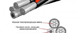
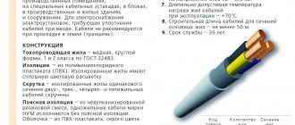
The structural composition of the cable with the abbreviation VVG is the following device:
- In the center there is a metal core that carries current, the material of which is copper. The vein can be round or sectoral in shape. It is common for multi-core cables of these types to contain a grounding or neutral conductor;
- The conductors can be distinguished by the bright colors on the shells: the grounding conductors are contained in light blue or light blue shells, and the grounding conductors are yellow-gray.
- A twist is formed from several cores, the voids of which are filled with insulating material;
- This structure is placed in a surface shell, which is made of a similar polyvinyl chloride.
Main characteristics
Let's consider the main technical and operational characteristics that determine the purpose and specification of the VVG cable.
Design features
A standard VVG consists of several current-carrying conductors with a round cross-section, each of which has an individual insulating layer of polyvinyl chloride. To prevent mechanical damage to the entire cable, it is covered with a protective sheath made of identical material.
Visually determining the difference between VVG and VVGng is almost impossible. Their design is the same, but the protective shell of the second type is less susceptible to burning, regardless of the circumstances. Thus, VVGng can be used not only for individual installation, but also for group installation.
The differences between VVGng and VVGng LS seem more fundamental. These cable types cannot be used interchangeably. Their operation is possible subject to strict compliance with established requirements and conditions. The structure of the VVGng LS modification is much more complex:
- monocore or stranded conductors of the first or second class, having a round or segmental cross-section;
- flame retardant PVC insulation;
- twist of two to five cores;
- filling in the form of non-flammable polyvinyl chloride plastic compound;
- PVC shell that can withstand high temperatures and open fire;
- two-core cables are produced with conductors of the same cross-section;
- if there are more current-carrying wires, then one of them may be smaller in cross-section (neutral or ground wire).
Weight
The cable weight will vary depending on the cross-section of the selected model. On average, the mass of a 1 km long VVGng ranges from 30 to 10,250 kg.
The table below shows the dependence of weight on the number of cores, the nominal cross-section of each of them and the outer diameter of the cable:
Cross section
The cross-section of one core in a VVG cable can vary from 1.5 to 240 square meters. mm. Most often you can find products on sale in which this value does not exceed 35 square meters. mm. Larger products will have to be ordered through the manufacturer or supplier.
The design of some models implies the presence of a neutral or ground wire. There are options in which the auxiliary conductor is produced with the same cross-section as the other current-carrying conductors. It is no less common to find a VVG with a ground or neutral wire of reduced size. However, in most cases it is the “ground” that is reduced.
If the cross-section on the protective conductor is smaller, then it is marked with the symbols “+1” (for example, VVG 4×3.5+1 - four wires of 3.5 sq. mm and one step smaller - 2.5 sq. mm). This cable is standardized along with the others.
Technical and operational indicators
The VVG cable is used to build electrical lines operating at air temperatures from -50 to +50 degrees. Celsius. During the installation process it can be no lower than -15. For single-core wires, the bending radius is equal to at least ten outer diameters of the product, for multi-core wires - from 7.5 and above.
Among the remaining operational parameters, we highlight the following:
- service life – up to 30 years;
- maximum temperature with prolonged exposure – +70 degrees. Celsius;
- maximum temperature during short circuit – +160 degrees. Celsius no more than four seconds;
- maximum temperature in emergency mode – up to +80 degrees. Celsius.
The resistance across the cable cores must not exceed the values shown in the table below:
| Nominal cross-section, sq. mm | Resistance of one core, Ohm/km |
| 1,5 | 12,1 |
| 2,5 | 7,41 |
| 4 | 4,61 |
| 6 | 3,08 |
| 10 | 1,83 |
| 16 | 1,15 |
| 25 | 0,77 |
| 35 | 0,524 |
| 50 | 0,387 |
Continuous current
When choosing cable cross-sections, ideally you should focus not on the resistance of the core, but on the value of the maximum permissible current. It depends on the number of cores, their cross-section and the chosen installation method (open or closed laying).
Check out the table below, which shows the dependence of long-term permissible currents on the number and cross-section of cores.
| Core cross-section, sq. mm | Continuous permissible current, A | ||
| one vein | two cores | three cores | |
| 1,5 | 24 | 21 | 19 |
| 2,5 | 33 | 28 | 26 |
| 4 | 44 | 37 | 34 |
| 6 | 56 | 49 | 45 |
| 10 | 76 | 66 | 61 |
| 16 | 101 | 87 | 81 |
| 25 | 134 | 115 | 107 |
| 35 | 208 | 177 | 165 |
VVG brand wire can be used in AC networks of 600 or 1000 V.
Specifications
Unom - from 0.66 to 1 kV; Frequency - 50 Hz; Operating temperatures, t - from -50 °C to +50 °C; Air humidity (at t0 +35 °C) – up to 98%; Working life: up to 30 years; Warranty from the date of purchase: 5 years; Installation without heating: at temperatures from -15 °C;
Maximum heating:
- In stable mode: +70 °C;
- In emergency situations: +80 °C;
- With one core - 10;
- With several cores - 7.5.
Minimum bend radius:
Construction length:
- from 1.5 mm2 to 16 mm2 - 450 m.
- from 25 mm2 to 70 mm2 - 300 m.
- from 95 mm2 and above - 200 m.
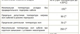
More clearly in the table:
Permissible cable heating temperature
The term “permissible cable heating temperature” most often refers to a parameter that determines the operating temperature of the cable at which the insulation retains its durability and practical qualities. However, when choosing a cable, it is worth using a broader approach, that is, also taking into account the heating temperature of the cores. In the first case, the ambient temperature is implied, in the second - the heating of the cable itself, caused by the electrical resistance of the current-carrying conductors.
Permissible heating temperature of cable insulation
When exposed to excessive heating or cooling, the insulation can begin to degrade in one way or another. This, in turn, can lead to damage to the cable, as well as devices and mechanisms connected to it. As a result, the permissible heating temperature of wires and cables depends primarily on the insulation material. “Ordinary” cables with plastic (PVC, polyethylene, polymers), paper, rubber insulation for operation in temperature conditions from -50 to +50 degrees (hereinafter the values are given in degrees Celsius). When this value is exceeded, the shell and insulation material begins to degrade to the point of melting. Supercooling, in turn, leads to mechanical destruction of the insulation - the appearance of cracks, breaks and other defects. For example, the permissible heating temperature of the VVGng cable in the standard version during operation is +50°C, the minimum is -50°C, and for a cable in the design of which PVC plastic with increased cold resistance is used can withstand temperatures up to -60°C inclusive. If you plan to operate the cable in more extreme temperature conditions, it is advisable to consider specialized models with insulation made of other materials - fluoroplastic, silicone and others. In addition, when operating in extremely cold conditions, cold-resistant versions are suitable.
Permissible heating temperature of cable core insulation
The permissible heating temperature of the cable cores also depends on the insulation material, and in some cases, on the operating voltage. The long-term permissible heating temperature of cable core insulation, depending on the type of insulation, is: • paper: ◦ up to 3 kV inclusive – 80°C; ◦ 6 kV – 65°C; ◦ 10 kV – 60°C; ◦ 20-35 kV – 50°C. • depleted impregnated paper: ◦ 1 kV – 80°C; ◦ 6 kV –75°C. • rubber – 65°C; • cross-linked polyethylene (XPE) and ethylene propylene rubber (EPR) - 90°C; • PVC plastic and polymer composition – 70°C; • oil-filled – 70-80°C depending on the type of gasket.
For all types of insulation, a short-term increase in temperature in emergency or start-up mode (overload) is permissible. The permissible temperature values, depending on the type of insulation, are: • depleted paper – 95°C, but not more than 10% of the operating time; • rubber – 110°C, but only during start-up mode; • PVC insulation and polymer composition - +80°C in overload mode; • SPE and EPR - +130°C in overload mode (in emergency mode); • oil-filled - 80°C, while the duration of continuous operation in emergency mode should be no more than 100 hours. The maximum period of operation in emergency mode is no more than 500 hours per year. The interval between overloads should not be less than 10 days. Operation of a paper-insulated cable at a voltage of 20 or 35 kW in emergency mode is not allowed. Operation of a paper-insulated cable at voltages up to 10 kV inclusive in emergency mode is permitted for no more than 5 days, taking into account permissible overload factors.
Estimated weight for VVG cable
| Core cross-section, mm., External ? cable, mm. | Weight of 1 km cable, kg. | ||
| With copper core | With aluminum core | ||
| 1.5 2.5 4 6 10 16 25 35 50 70 95 120 150 185 240 | 10.7 11.8 14.0 15.3 17.4 20.3 24.6 27.4 31.8 34.8 38.8 42.0 46.2 50.2 56.6 | 170 231 343 456 674 1007 1537 2035 2844 3811 5051 6246 7763 9472 12235 | — 151 216 265 356 499 743 940 1301 1625 2120 2544 3135 3765 4831 |
Technical specifications
VVG cable characteristics: at 25 degrees, the electrical resistance should not be less than 7 - 10 MOhm. The larger the cross-section, the higher the resistance.
In production, the cable must be tested with alternating voltage with a frequency of 55 Hz for 9 minutes. The voltage is generated between the wires and should be no more than 3 kV for products with a nominal value of 0.65 kV. The diameter of the VVG cable can reach 55mm2. The minimum insulation thickness of the VVG cable is 0.44 mm. All characteristics and parameters can be read in full in the product certification.
VVG cable technical specifications
VVG cable: scope
When laying/replacing wiring and other electrical work in private houses and apartments, VVG cable is most often used. This is due to the wide range of applications and relatively low price. It can be used in electrical networks with a voltage not higher than 1000 V and a frequency of 50 Hz (special types up to 100 Hz). That is, it is suitable for single-phase and three-phase networks. Can be installed indoors and outdoors. When installed externally, it requires additional protection. It is placed in HDPE pipes, cable trays, etc.
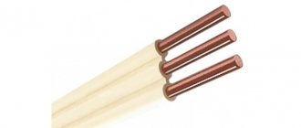
Three-core cable VVG
It is not recommended to use its gaskets in the ground, since it does not have armor, which is why it quickly fails. If desired, it can be laid in the ground, but in an additional protective shell (corrugated pipe) and/or in a cable duct.
The scope of application largely depends on the modification: the type of material from which the core sheaths and the cable itself are made. We'll talk about this in more detail a little further.
