Design features
From a technical point of view, the AIR electric motor is one of the types of asynchronous electric machines. This variety first came into use back in 1973 and replaced the 4A and AM brands thanks to a new international standard that established its parameters and technical features. A structural example of asynchronous electric motors is shown in the figure below:
Rice. 1. Design of the AIR electric motor
As you can see, the AIR engine consists of the following main structural elements:
- Housing - made of cast iron or lightweight alloys, designed to hold internal parts and fasten to the working surface.
- Stator magnetic circuit - used as a medium for conducting magnetic flux from the windings to the rotor.
- Stator windings are made of copper conductors with varnish insulation, as a rule, they have an additional layer. Designed for the flow of alternating current, which generates electromagnetic waves. The winding wires are laid in the stator grooves.
- The rotor is phase or short-circuited; the phase rotor consists of a metal shaft on which there is a squirrel cage and windings placed in its grooves. The squirrel-cage rotor is a monolithic block made of ferromagnetic material. The rotor is designed to rotate inside the electric motor due to the influence of electromagnetic forces.
- Borna - the terminal box is designed to connect the electrical power cable, allowing you to change the connection diagram of the windings.
Explanation of markings
Rice.
2. Example of designation on a nameplate Like any device, AIR electric motors are produced with different operating parameters, which are displayed both in the passport data and in its markings.
Let's consider the decoding of one of the units of the AIR series:
AIR 80 A 4 U2 IM2081 IP54
Here the marking of the electric motor indicates the following data:
- AIR - indicates the brand (A - asynchronous, IR - manufactured according to the Interelectro standard);
- 80 – axis height value, expressed in millimeters; AIR electric motors are manufactured with dimensions from 56 to 355 mm;
- A – shaft length, in this type of electric machine the designation is done in letters in order from smallest to largest;
- 4 – number of poles, which determines the possible rotation speed;
- U2 – climatic version, which determines the permissible parameters of the engine type;
- IM2081 – installation method, which determines the method of installing the mechanism drive in relation to the working surface;
- IP54 – degree of dust and moisture protection of the device.
Principle of operation
The operating principle of two and polyphase motors was developed by Nikola Tesla and patented. Dolivo-Dobrovolsky improved the design of the electric motor and proposed using three phases instead of the two used by N. Tesla.
The improvement is based on the fact that the sum of two sinusoids of equal frequency differing in phase gives the sum of a sinusoid; this makes it possible to use three wires (in the fourth “zero” wire the current is close to zero) with a three-phase system versus the four necessary wires with a two-phase current system.
The set of moments created by individual conductors forms the resulting torque of the motor; an electromagnetic pair of forces arises, which tends to turn the rotor in the direction of movement of the electromagnetic field of the stator.
The rotor begins to rotate and acquires a certain speed, the magnetic field and the rotor rotate at different speeds or asynchronously. In relation to asynchronous motors, the rotor rotation speed is always less than the rotation speed of the stator magnetic field.
How does a three-phase asynchronous motor work?
The torque of the engine is created by the forces of interaction between the magnetic field and the currents induced by it in the rotor, and the strength of these currents is determined by the relative frequency of rotation of the field in relation to the rotor, which itself rotates in the same direction as the field.
Therefore, if the rotor rotated with the same frequency as the field, then there would be no relative motion. Then the rotor would be at rest relative to the field and no induced e would arise in it. d.s., that is, there would be no current in the rotor and no forces could arise that would cause it to rotate. From this it is clear that a motor of the described type can only operate at a rotor speed slightly different from the field speed, that is, from the current frequency.
Therefore, in technology such motors are usually called “asynchronous” (from the Greek word “synchronos” - coinciding or coordinated in time, the particle “a” means negation). If machines driven by an engine require a different rotation speed than the engine provides, then they prefer to use gear or belt drives with different gear ratios.
It goes without saying that as the engine load increases, that is, the mechanical power it produces, not only the current in the rotor must increase, but also the current in the stator so that the engine can absorb the corresponding electrical power from the network. Therefore, when working with engines, the following rules must be strictly observed:
- It is always necessary to select an engine of such power as is actually required by the machine it powers.
- If the motor load does not reach 40% of normal, and the stator windings are connected in a delta, then it is advisable to switch them to a star.
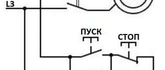
- In order to reverse the direction of rotation of the motor shaft, it is necessary to swap the two line wires connected to the motor. This is easy to do using a double pole switch.
This is done automatically due to the fact that the current in the rotor also creates its own magnetic field in the surrounding space, affecting the stator windings and inducing some e.g. d.s. The connection between the magnetic flux of the rotor and the stator, or, as they say, the “armature reaction”, causes changes in the current in the stator and ensures that the electrical power taken from the network is matched with the mechanical power supplied by the motor.
It will be interesting➡ What is an asynchronous motor and the principle of its operation
Specifications
The installation and subsequent operation of the AIR electric motor must be adjusted to the mechanical load connected to its shaft, connection and operating conditions. The technical characteristics of the electric machine are selected in accordance with the above parameters. The engine characteristics are also indicated in the passport or on the nameplate.
Key technical data include:
- Power – determines the amount of electricity processed; for AIR electric motors this parameter ranges from 0.12 to 315 kW.
- The supply voltage depends to a certain extent on the winding connection diagram. AIR electric motors can be connected either in star or triangle, so the voltage is indicated for both methods - 220/380 or 380/660V.
- Rotation speed is the number of revolutions per unit of time; for the AIR brand it can range from 750 rpm to 3000 rpm.
- Efficiency - determines the ratio between energy expended and work done.
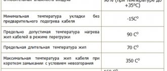
- The permissible temperature range is usually from – 40 to + 45ºС.
- Type of installation - in total there are three methods for the AIR electric motor: IM1081 - on the frame (horizontally), IM2081 both on the frame and on the flange (both horizontally and vertically), IM3081 only on the flange (vertically). An example of basic design options is shown in the figure below:
Rice. 3. Method of mounting the AIR electric motor
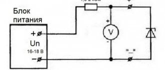
- Electrical and magnetic losses are determined by the open circuit voltage and short-circuit current.
- Geometric dimensions - indicate the main dimensions and distances from the elements of the electric machine to the nearest parts with which the motors are used.
- The degree of dust and moisture protection is indicated by two Latin letters IP and a pair of numbers, one of which determines resistance to dust, and the second to moisture.
The general industrial purpose of some of them involves technical features, which are indicated by the corresponding letters with which the engines are produced:
- B – ensures operation in high temperature conditions;
- B – built-in electrical machines;
- C – with increased sliding parameter;
- E – with the function of forced rotor braking.
- E2 – with manual braking control.
- ZE is a three-phase device for connecting to a single-phase network.
- F – for pumping units.
- RZ - in motor-gear devices.
- Sh – general industrial electric motors for the clothing industry.
- P – with high precision mounting characteristics.
- F – oil-resistant version.
- A – used in nuclear power plants.
- X2 – increased chemical resistance.
Types of designation in the AIR series
In the AI series, three types of designation are accepted: basic, basic and complete. The basic designation is a combination of symbol elements that define the series, its power, rotation speed (series designation, option for linking power to installation dimensions, height of the axis of rotation, installation dimension along the length of the frame and the length of the stator magnetic circuit, number of poles), for example: AIR200 MB ( series AI, linkage according to option P, height of the axis of rotation 200 mm, length of the housing according to installation dimensions M, number of poles 6).
The main designation is a combination of the basic designation of the electric motor with the designation of the type of protection and cooling, electrical and structural modification, specialized design and design according to environmental conditions, for example: AIRBS100M4NPT2 (AIR100M4 - basic designation, B - closed design with natural cooling without blowing, C - with increased slip, N - low noise, P - with increased accuracy of installation dimensions, T - for tropical climates, 2 - placement category).
Full designation - a combination of the main designation with additional electrical and design characteristics, for example: AIRBS100M4NPT2 220/380 V, 60IM218I, KZ-N-3, F-100, (AIRBS100M4NPT2 - main designation, 220/380 V - voltage, 60 - network frequency , IM2181 - version according to the installation method and at the end of the shaft, KZ-N-3 - version of the output device and the number of fittings, F100 - version of the flange panel).
So, the complete standardized designation describes almost all engine characteristics and has the form - AIR ХХХ DPSI, КККК ММММММ ЗЗЗЗ, where
AIR - series designation;
ХХХ - dimensions, height of the engine axis in millimeters (56, 63 ... 355);
D – stator package length, installation size (A, B, L, S, M);
P – number of pole pairs;
SI – special version (B, E, E2, Zh, P3, Sh, P, F, A, X2);
KKKK – version according to climatic conditions (U1...U3, UHL2, UHL4, T2, OM2);
MMMMMMM – installation method (IM1081, IM2081, IM2181, IM1082, IM2082, IM5010);
ZZZZ – degree of protection of the shell (IP44, IP54, IP55).
The best manufacturers
In view of the constant filling of the market with electric machines of the most varied quality, the question is quite acute when purchasing an AIR electric motor. By purchasing such a unit, the user expects to receive in return long-term, uninterrupted operation, since asynchronous machines are much more reliable and relatively rarely fail.
However, in practice, various counterfeits often surface, usually cheap Chinese products, and sometimes they try to pass them off as newly minted domestic manufacturers of engines in the main industrial sector. Therefore, to buy an AIR electric motor, you should choose proven brands that meet the standards, and their units can withstand the declared operating modes.
The list of the best manufacturers of electric motors of the AIR series is given in the table below:
Table: list of the best manufacturers of AIR electric motors
| Manufacturer name | Short description |
| SLEMZ (Kharkov electromechanical plant) | It produces AIR electric motors with power from 0.75 to 75 kW of various designs. |
| "Ukrelectromash" (Kharkiv electrical plant) | Produces a low-power line of electric machines of the AIR brand |
| "ELDIN" (Yaroslavl plant) | One of the largest manufacturers of asynchronous machines in Russia |
| Sibelektromotor (Tomsk plant) | Mostly focused on the production of crane electric motors. |
| "Electrodvigatel" (Mogilev plant) | Focused on a wide range of drive products |
| "Polesieelectromash" (Luninets plant) | They not only manufacture, but also repair AIR electric motors |
Changing the rotor speed
The parallel windings of two phases form one pair of poles shifted in space by 120 degrees. The series connection of the windings forms two pairs of poles, which makes it possible to reduce the rotation speed by half. To regulate the rotor rotation speed by changing the current frequency, a separate current source or an energy converter with adjustable frequency, made on thyristors, is used.
At the moment of starting, the engine develops quite a significant torque, and since its inertia is relatively small, the rotor rotation frequency quickly increases and is almost equal to the field rotation frequency, so that their relative frequency becomes almost equal to zero and the current in the rotor quickly decreases.
It will be interesting➡ Single-phase asynchronous motors in the service of humanity
For low- and medium-power motors, short-term overload during startup does not pose a danger, but when starting very powerful motors (tens and hundreds of kilowatts), special starting rheostats are used that weaken the current in the winding; As the rotor reaches normal speed, these rheostats are gradually turned off.
As the engine load increases, the rotor rotation speed decreases slightly, the field rotation frequency relative to the rotor increases, and at the same time the rotor current and the torque developed by the engine increase.
However, to change the engine power from zero to normal, a very small change in rotor speed is required, up to about 6% of the maximum value. Thus, the three-phase asynchronous motor maintains an almost constant rotor speed even with very wide load fluctuations.
It is in principle possible to regulate this frequency, but the corresponding devices are complex and uneconomical and therefore are used very rarely in practice. If machines driven by an engine require a different rotation speed than the engine provides, then they prefer to use gear or belt drives with different gear ratios.
Nuances of operation
In the case of installation and subsequent use of basic AIR electric motors, it is important to observe and take into account some of the nuances specified by the manufacturer, namely:
- The electric motor must be connected through a protection system against short circuit currents, overheating, phase failure, overloads, etc.
- When performing installation work or connecting the AIR electric motor, it is important to ensure an air flow for cooling; the casing itself must be moved away from obstacles by at least 20mm.
- In case of couplings, the shaft of the AIR electric motor is aligned coaxially with the load.
- Regardless of the connection method, subsequent balancing of the load on the shaft is required.
- It is important to consider that the rotor is balanced without keys.