Main characteristics
In order to determine the feasibility of manufacturing a generator using neodymium magnets, you need to consider the main characteristics of this material, which are:
- Magnetic induction B is a strength characteristic of a magnetic field, measured in Tesla.
- Residual magnetic induction Br is the magnetization possessed by a magnetic material when the external magnetic field strength is zero, measured in Tesla.
- Coercive magnetic force Hc - determines the resistance of a magnet to demagnetization, measured in Amperes/meter.
- Magnetic energy (BH)max - characterizes how strong the magnet is.
- Temperature coefficient of residual magnetic induction Tc of Br – determines the dependence of magnetic induction on the ambient temperature, measured as a percentage per degree Celsius.
- Maximum operating temperature Tmax - determines the temperature limit at which the magnet temporarily loses its magnetic properties, measured in degrees Celsius.
- Curie temperature Tcur - determines the temperature limit at which a neodymium magnet is completely demagnetized, measured in degrees Celsius.
The composition of neodymium magnets, in addition to neodymium, includes iron and boron and depending on their percentage, the resulting product, the finished magnet, differs in classes, differing in their characteristics given above. A total of 42 classes of neodymium magnets are produced.
The advantages of neodymium magnets that determine their demand are:
- Neodymium magnets have the highest magnetic parameters Br, Hsv, Hcm, VN.
- Such magnets have a lower cost compared to similar metals containing cobalt.
- They have the ability to operate without loss of magnetic characteristics in the temperature range from – 60 to + 240 degrees Celsius, with a Curie point of +310 degrees.
- From this material it is possible to make magnets of any shape and size (cylinders, disks, rings, balls, rods, cubes, etc.).
How to use the energy of weak winds?
The use of weak wind flows can be done in two directions:
- the use of devices that are structurally different from common models
- use of more efficient generators capable of producing sufficient energy at low rotation speeds
Practice shows that the search should be conducted in both directions. The development of new versions of the impeller, capable of reliably rotating at low flows, is ongoing, and there are already many prototypes demonstrating quite successful results.
Equally active is the development of productive generators that make it possible to use weak winds as a source of energy. Thus, axial generators on neodymium magnets give a great effect and allow you to obtain a good amount of energy. Some craftsmen note the emerging need to limit the possibility of accelerating the rotation of the rotor, i.e. motion stability is needed.
Rotor options capable of efficient operation in low winds have been known for decades. Currently, designs by Tretyakov and Onipko can be used; sailing wind turbines are highly efficient. An integrated approach to modernizing the design of wind generators, when both the impeller and the generator are simultaneously modified, gives a positive result.
The situation is somewhat complicated by the unofficial nature of the work being carried out. If an inventor wants to share his findings with the public, then everyone will know about them, but if he does not consider it necessary to make his findings public, then the information will become closed from discussion and comprehension.
Wind generator on neodymium magnets with a power of 5.0 kW
Currently, domestic and foreign companies are increasingly using neodymium magnets in the manufacture of low-speed electric current generators. Thus, Salmabash LLC, Gatchina, Leningrad Region, produces similar permanent magnet generators with a power of 3.0-5.0 kW. The appearance of this device is shown below:
The generator housing and covers are made of steel, later coated with paint and varnish materials. The housing is equipped with special fastenings that allow you to secure the electrical device to the supporting mast. The inner surface is treated with a protective coating that prevents metal corrosion.
The generator stator is made of electrical steel plates.
The stator winding is made of enamel wire, allowing the device to operate for a long time at maximum load.
The generator rotor has 18 poles and is mounted in bearing supports. Neodymium magnets are placed on the rotor rim.
The generator does not require forced cooling, which is carried out naturally.
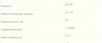
Technical characteristics of the 5.0 kW generator:
- Rated power – 5.0 kW;
- Rated frequency – 140.0 rpm;
- Operating rotation range – 50.0 – 200.0 rpm;
- Maximum frequency – 300.0 rpm;
- Efficiency – not less than 94.0%;
- Cooling – air;
- Weight – 240.0 kg.
The generator is equipped with a terminal box through which it is connected to the electrical network. The protection class corresponds to GOST 14254 and has a degree of IP 65 (dust-proof design with protection from jets of water).
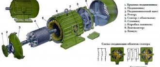
The design of this generator is shown in the figure below:
where: 1-body, 2-bottom cover, 3-top cover, 4-rotor, 5-neodymium magnets, 6-stator, 7-winding, 8-coupling half, 9-seals, 10,11,12-bearings, 13 - terminal box.
Advantages and disadvantages
The advantages of wind generators made using neodymium magnets include the following characteristics:
- High efficiency of devices, achieved by minimizing friction losses;
- Long service life;
- No noise or vibration during operation;
- Reduced costs for installation and installation of equipment;
- Autonomy of operation, allowing operation without constant maintenance of the installation;
- Possibility of self-production.
The disadvantages of such devices include:
- Relatively high cost;
- Fragility. Under strong external influence (impact), a neodymium magnet can lose its properties;
- Low corrosion resistance, requiring special coating of neodymium magnets;
- Dependence on operating temperature – when exposed to high temperatures, neodymium magnets lose their properties.
Most popular models
Currently, the most popular generators are models from, U-Polemag, Vega, and Verano-Co. They occupy a large part of the device market.
Vega produces devices that operate on the principle of magnetic induction. This idea was realized by the famous physicist Adams. The price often depends on the power and size of the device. The minimum cost is 45 thousand rubles. This manufacturer has a number of advantages:
- Products from are very environmentally friendly.
- The generators are completely silent, which allows them to be installed anywhere.
- The devices are relatively compact.
- The manufacturer has quite a few models, the power of which starts from 1.5 kW and reaches up to 10 kW.
The minimum service life is 20 years. Batteries must be replaced every 3-4 years.
"Verano-Co" is a Ukrainian manufacturer that uses only high-quality components for its products. It produces generators for both domestic and industrial purposes. The operating principle of the alternative energy source is the same as that of other magnetic units. The cheapest model costs 50 thousand rubles. Prices for devices reach 200 thousand rubles.
You may be interested in Uninterruptible power supplies (UPS) for computers
U-Polemag is a Chinese manufacturer. Represents the largest variety of generator models. The standard efficiency of the devices is 93%. Maximum energy loss is 1%. Often purchased for household use. It has compact dimensions, low noise level and light weight. The package includes cooling systems. The maximum duration of use reaches 15 years. Prices for the model range start from 30 thousand rubles. and reach 90 thousand rubles.
Energizistem produces vertical devices. Consumers do not have a clear opinion about the quality and power of devices. Prices for generators are a little high and start at 50 thousand rubles.
Phases - which is better - three or one?
Many lovers of electrical equipment follow the path of least resistance and, in order not to bother, opt for a single-phase stator for a windmill. However, it has one unpleasant feature that neutralizes the ease of assembly - vibration when loaded, due to the variability of current output. After all, the amplitude of such a stator is abrupt, reaching a maximum when neodymium magnets are located above the coils, and then dropping to a minimum.
But when the generator is made using a three-phase system, there are no vibrations, and the power indicator of the windmill has a constant value. The reason for this difference is that the current, falling in one phase, at the same time increases in the other. As a result, a wind generator operating in a three-phase system can be up to 50% more efficient than the exact same one using a single-phase system. And most importantly, a loaded three-phase generator does not produce vibration, therefore, the mast does not give rise to complaints about the wind generator to the supervisory authorities from ill-wishers among neighbors, since it does not create an annoying hum.
Features of the rotor and stator
Transistor generator
To make an effective generator using neodymium alloy magnets with your own hands, consider the following recommendations when assembling:
- To increase strength, the disc is made of steel. Its thickness is made no less than that of the magnets themselves. Otherwise, part of the force field will dissipate. If the proportions are observed correctly, the sewing needle will not be attracted to the reverse side of the assembled product;
- The distance between individual magnets is made equal to or more than half the width of the products;
- The thickness of the assembled stator is made equal to or less than the thickness of neodymium magnets;
- A three-phase magnetic generator is made in proportions of 3 to 3 or 4 to 3 (the number of magnets/induction coils, respectively).
For your information. The magnets are attached, strictly observing the alternation of poles. To avoid mistakes, marks are made in advance with a marker on the corresponding edges.
Rotor creation process
The author of the development decided to make the basis of the generator a car hub with brake discs, since it is powerful, reliable and perfectly balanced.
When you start making a windmill with your own hands, you should first prepare the base for the rotor - the hub - and clean it of dirt, paint and grease. Then start gluing the permanent magnets. To create this wind generator, twenty of them were used on a disk. The size of the neodymium magnets was 25x8 millimeters. However, both their number and their size can vary depending on the goals and objectives of the person creating the wind generator with his own hands. However, to obtain one phase it will always be correct to equalize the number of poles to the number of neodymium magnets, and for three phases to maintain the ratio of poles and coils - two to three or three to four. The magnets should be positioned taking into account the alternation of poles, and as accurately as possible, but before you start sticking them, you need to either create a paper template or draw lines dividing the disk into sectors. To avoid mixing up the poles, we make marks on the magnets. The main thing is to fulfill the following requirement: those magnets that stand opposite each other must be turned with different poles, that is, attract each other.
The magnets are glued to the disks using super glue and filled in. You also need to make borders along the edges of the disks and in their center, either by wrapping tape or molding them from plasticine to prevent spreading.
Modification of a car generator
Creating a permanent magnet rotor requires quite a serious intervention in the design. It is necessary to reduce the diameter by the thickness of the magnets plus the thickness of the steel sleeve, which is placed on the rotor to form a continuous magnetic flux and at the same time serves as a landing pad for the magnets. Some experts do without a sleeve, installing magnets directly on the rotor with a reduced diameter and fixing them with epoxy.
The manufacturing process requires the participation of production equipment. The rotor is clamped into the lathe and the layer is carefully removed so that the installed magnets rotate with minimal clearance, but quite freely. The magnets are installed on the rotor plates with alternating polarity.
The greatest effect can be achieved when installing relatively small-sized magnets arranged in rows in the longitudinal direction. A smooth and powerful magnetic flux is achieved, acting on the stator power windings with uniform density at all points.
Making a rotor from a hub and brake disc
The considered method applies to ready-made generators that require minor design changes. Such devices include car generators, which are often used by amateur designers as a basic device. Often, generators are assembled completely independently, without having a ready-made device.
In such cases, they act somewhat differently. The basis is a car hub with a brake disc. It is well-balanced, durable and adapted to certain types of loads. In addition, the size of the hub allows a large number of magnets to be placed around the circumference, allowing three-phase voltage to be obtained.
Magnets with alternating polarity are placed at a distance equidistant from the center. Obviously, the highest number can be set by gluing them as close to the outer edge as possible. The most accurate indicator will be the size of the magnets, which will determine the possibility of placement at a certain distance. The number of magnets must be even so that the rhythm of alternating poles during rotation does not break down.
Gluing magnets to the hub is done using any glue; the best option is epoxy resin, which is used to completely fill the magnets. This protects them from moisture or mechanical stress. Before pouring, it is recommended to make a plasticine rim along the edge of the hub to prevent the epoxy from flowing down from the hub.
The design of the generator on a car hub is most convenient when making a vertical windmill.
It is noteworthy that a similar scheme can be used without a hub, on a disk cut from ordinary plywood. This design is much lighter, allows you to choose a convenient size, which makes it possible to create a sensitive and productive device.
Device
The low-speed machine is based on a low-voltage constant-magnet motor. They have a low rotation threshold from which current production begins. A high-quality device needs 300-500 rpm. Since the design is low-speed, a multiplier gearbox is required. The required ratio is 1:12, but 1:15 is better. In this case, 20 revolutions of the blades will turn into 300, which is enough to produce current.
Constant magnet motors
In some devices, the motor is replaced with a self-generator, which increases the required rotation speed. For this purpose, a multiplier with a large ratio is installed. Its work provokes a gradual weakening of performance due to wear and tear.
Gearboxes and multipliers serve to reduce the speed of rotation of the wind generator wheel, and with their help you can change the position of the plane of rotation
Low-speed windmills are used in places with low winds (marked in yellow-green on the wind map) if the current demand does not exceed 3 kW per hour.
Blades
The correct device has a variable profile, and its wingspan is at least 2 meters. Production is labor-intensive, requires accurate calculations and undergoes a large number of tests before use. Such blades are capable of developing the required speed, extracting energy.
Due to the use of gearboxes and multipliers, the appearance and location of the blades can be anything, so engineers are trying to select the optimal designs with maximum efficiency
You should not make your own blades. If you want to try it out, use a thick-walled plastic pipe. The diameter must be sufficient to make a full-fledged blade. Before starting work, make calculations based on the desired power of the wind generator. A well-made device can develop up to 300-400 watts per hour, which will be enough to illuminate several rooms in a private house.
Generator
The choice of generator depends on the possible rotation speed. For low-speed installations, a permanent magnet motor is sufficient. Depending on the speed, a multiplier is used. It allows each revolution to be multiplied by a factor, which reduces the time it takes to start production.
The generator for a low-speed wind generator is selected based on the required consumption of the facility, taking into account efficiency and power reserve
For rotor durability, a special intermediate shaft is used. It has a built-in bearing that stabilizes the support. The transfer of energy from the blades to the rotor is carried out mechanically. A high-quality part allows the shaft to slightly change its position, which reduces wear. A good bearing is a double row one, preferably self-aligning. Three-row is better, but more expensive.
Emergency weather vane
The device allows you to save a wind generator in hurricane weather. Strong wind stretches the spring, causing the rotor to change position. Gradually it lies along the air flow, losing momentum. This is impossible with the wind directed strictly parallel to the ground, which is quite rare.
An emergency weather vane is necessary for wind generators to prevent destruction in cases of hurricane winds.
Therefore, an emergency weather vane is used to protect the device. With its help, the need to disconnect the rotor from the system is determined. A hurricane can completely destroy a wind generator. That's why weather vanes are used - with their help it is possible to preserve the base, in the worst case, losing the blades.
Low-speed models of wind generators can withstand large gusts of wind, however, they have limits, and therefore it is necessary to provide protection for the blades
Industrial wind turbines use an electronic weather monitoring system. The pitch of the blades is controlled automatically - this helps protect the device. In addition, in such systems the wings are made of durable composite materials.
Current collector
The device is located at the top of the mast and requires regular cleaning. To do this you will have to get a long stepladder.
There is also the option of laying the windmill on the ground, carrying out cleaning work, and then raising it again. This is painstaking and time-consuming, but necessary.
Current collectors for wind generator
Industrial devices are large in size, so the ladder to the top is located inside the mast.
Windmill with axial generator on neodymium magnets
The strongest magnets with optimal parameters for use in generator design are neodymium magnets . They are somewhat more expensive than conventional ones, but they are many times superior and make it possible to create a powerful device in a relatively compact size.
There is no fundamental difference in the design. Neodymium magnets are manufactured in various form factors, allowing you to choose the most convenient option for yourself - thin oblong bars, tablet shape, cylinders, etc. if a metal rotor is used, then it is not necessary to glue the magnets; they themselves are attached to the base with force. All that remains is to fill them with epoxy to protect them from corrosion.
Winding method for windmill stator coil
In order for a do-it-yourself wind generator on neodymium magnets to work with maximum efficiency, the stator coils should be calculated.
However, most craftsmen prefer to do them by eye. For example, a low-speed generator capable of charging a 12 V battery starting from 100 - 150 rpm should have from 1000 to 1200 turns in all coils, equally divided between all coils. An increase in the number of poles leads to an increase in the frequency of the current in the coils, due to which the generator, even at low speeds, produces more power. The coils should be wound with thicker wires if possible in order to reduce the resistance in them. This can be done on a mandrel or on a homemade machine.
In order to figure out what power potential the generator has, spin it with one coil, since, depending on how many neodymium magnets are installed and what their thickness is, this indicator may differ significantly. The measurements are carried out without load at the required number of revolutions. For example, if a generator at 200 rpm provides a voltage of 30 V, having a resistance of 3 ohms, then subtract 12 V (battery supply voltage) from 30 V and the resulting result is 18 divided by 3 (resistance in ohms) we get 6 ( current in amperes), which will go from the wind generator to charge the battery. However, as practice shows, due to losses in the wires and diode bridge, the actual indicator that the magnetic axial generator will produce will be less.
It is better to take magnets for creating a wind generator in the shape of a rectangle, since their field extends along the length, unlike round ones, the field of which is concentrated in the center. Coils are usually wound round, although it is better to make them somewhat elongated, which provides a larger volume of copper in the sector, as well as straighter turns. The hole inside the coils must be equal to or greater than the width of the magnets.
The thickness of the stator should be the same as the magnets. The form for it is usually plywood; for strength, fiberglass is placed under the coils and on top of them, and the whole thing is filled with epoxy resin. In order to prevent the resin from sticking to the mold, the latter is lubricated with any fat or adhesive tape is used. The wires are first brought out and fastened together, the ends of each phase are then connected with a triangle or an asterisk.
Electrical and technical parameters of the generator
The voltage is calculated using the formula:
Homemade generator
U=2*Ch*KP*KK*KV*MI*P, where:
- U – voltage in Volts;
- H – frequency of rotation of the generator rotor per second;
- KP – number of magnetic poles;
- КК – number of induction coils in the stator;
- KV – the number of turns of the conductor in one induction coil;
- MI is the magnetic induction in T, which is formed in a standard gap (2 mm);
- P – surface area of one neodymium magnet, in sq. m.
If simple coils are used, a magnetic induction of 0.5 Tesla is taken for calculation. When adding an electrical steel core, the value is increased to 0.7-0.9 T.
For your information. The formula is valid when connecting the windings in a triangle. If a three-phase generator is assembled using a star circuit, the resulting value is multiplied by a correction factor of 1.7.
After calculating the voltage, you need to find out the resistance in the windings. After this, it will be easy to determine the current and power. For a copper conductor, the resistivity is 0.0175 Ohm per mm2/meter. To calculate the total value, use the formula:
C= (US*D)/PP, where:
- C – resistance, in Ohm;
- US – resistivity of a certain material;
- D – conductor length in meters;
- PP – conductor cross-sectional area, mm sq.
To calculate the current, subtract the voltage of the battery connected for charging from the voltage of the magnetic generator at idle. The resulting value is divided by the resistance value calculated using the previous formula.
Increasing/decreasing the speed changes the current accordingly while keeping the voltage at the battery terminals constant. To calculate the performance of a wind turbine in different modes, use the standard formula:
P=I*U, where:
- P – power, Watt;
- I – current strength, Ampere;
- U – voltage, Volt.
Technical characteristics of the DC generator
The operation of the generator is characterized by dependencies between the main quantities, which are called its characteristics. The main characteristics include:
- dependencies between values when idling;
- characteristics of external parameters;
- adjusting values.
We partially disclosed some adjustment characteristics and idle speed dependencies in the “Classification” section. Let us dwell briefly on the external characteristics that correspond to the operation of the generator in nominal mode. The external characteristic is very important, since it shows the dependence of voltage on load, and is taken at a stable armature speed.
The external characteristic of a direct current generator with independent excitation is as follows: this is a curve of voltage versus load (see Fig. 5). As can be seen in the graph, a voltage drop is observed, but it does not greatly depend on the load current (while maintaining the speed of the engine rotating the armature).
Rice. 5. External characteristics of the GPT
In generators with parallel excitation, the dependence of voltage on load is more pronounced (see Fig. 6). This is due to a drop in the excitation current in the windings. The higher the load current, the faster the voltage at the generator terminals will drop. In particular, with a gradual drop in resistance to the short-circuit level, the voltage will drop to zero. But a sudden short circuit in the circuit causes a backlash from the generator and can be fatal for an electric machine of this type.
Rice. 6. Characteristics of GST with parallel excitation
An increase in load current with series excitation leads to an increase in EMF. (see top curve in Fig. 7). However, the voltage (lower curve) lags behind the emf because some of the energy is wasted in electrical losses from the eddy currents present.
Rice. 7. External characteristics of a generator with series excitation
Please note that when it reaches its maximum, the voltage begins to drop sharply with increasing load, although the EMF curve continues to tend upward. This behavior is a disadvantage that limits the use of this type of alternator.
In generators with mixed excitation, counter-connections of both coils are provided - serial and parallel. The resulting magnetizing force with consonant switching is equal to the vector sum of the magnetizing forces of these windings, and with counter switching - the difference of these forces.
How to agree on the parameters of functional parts
The energy potential of the blades must correspond to a specific asynchronous motor or a self-assembled rotor with magnets. In case of significant deviations, in order to obtain sufficient electrical power, it will be necessary to create new products with the required parameters. The reverse situation is also unacceptable. Too large blades are not able to rotate quickly. Strong winds increase the risk of destruction of such structures.
To avoid mistakes, make a table with equipment operating modes at different rotation speeds in increments of 50-100 rpm. Next, they use specialized calculators that, based on the given values, calculate the geometric parameters of the screw. These products are created from suitable wood, metal, and plastic. Standard polyvinyl chloride pipes for external sewer networks are suitable as blanks.
Creating a device with your own hands
Obtaining electrical energy in huge quantities without consuming fuel is a tempting and quite feasible idea. The creation of such a device can be considered using the example of the Adams generator. For self-assembly you will need:
- Magnets. The larger the magnet, the more it affects the induction field, as well as the amount of energy generated. For a low-power generator, small pieces are suitable. It is desirable that the sizes be the same. For normal operation, 15 pieces are enough. The positive pole of one magnet must be installed opposite the positive pole of the other. If this condition is not met, then there will be no induction field.
- Copper wires.
- Two coils. You can get them from old engines or wind the wire yourself.
- Sheet steel for making the body.
- Bolts, washers, screws and nails. They are necessary for fastening small elements.
You might be interested in: Design and principle of operation of a frequency converter
First, the magnet must be secured to the base of the coil. This can be done by drilling a hole in it and then securing it with bolts. The wires on the coils should be 1.25 mm thick and have a layer of insulation. The coils should be mounted on a metal frame so that there are small gaps between the ends. This is required for free rotation of the main element.
At this stage, the device can already be used. It is quite simple to check the correct assembly: you should manually turn the magnets. If the structure is assembled correctly, voltage will arise at the ends of the winding.
This is the most primitive generator, powered by magnets. But based on such a scheme, it is possible to create a device that will be able to provide electricity to the entire house. You can also purchase ready-made devices from trusted manufacturers.