This is an automatic circuit that controls the charging of the battery from solar panels and other power sources. It is based on 555 integrated circuits and charges the battery when its charge drops below a predetermined level, and then stops charging when the battery reaches its upper voltage limit.
Principle of operation
If there is no current from the solar battery, the controller is in sleep mode. It doesn't use a single watt from the battery. After sunlight hits the panel, electric current begins to flow to the controller. It should turn on. However, the indicator LED along with 2 weak transistors turns on only when the current voltage reaches 10 V.
Once this voltage is reached, current will flow through the Schottky diode to the battery . If the voltage rises to 14 V, amplifier U1 will start working, which will open the MOSFET transistor. As a result, the LED will go out and two low-power transistors will close. The battery will not charge. At this time, C2 will be discharged. On average this takes 3 seconds. After capacitor C2 discharges, the hysteresis of U1 will be overcome, the MOSFET will close, and the battery will begin to charge. Charging will continue until the voltage rises to the switching level.
Charging occurs periodically. Moreover, its duration depends on the charging current of the battery and how powerful the devices connected to it are. Charging continues until the voltage reaches 14 V.
The circuit turns on in a very short time. Its activation is influenced by the charging time of C2 with current, which limits transistor Q3. The current cannot be more than 40 mA.
Solar controller
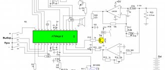
A diagram of an efficient 12V charger (solar controller) is shown, with battery protection from low voltage.
Device characteristics
Low power consumption in idle mode The circuit was designed for small and medium-sized lead-acid batteries and consumes low current (5 mA) in idle mode. This increases the lifespan of the batteries.
Easily available components The device uses regular components (not SMD) that can be easily found in stores. There is no need to flash anything, the only thing you will need is a voltmeter and an adjustable power supply to configure the circuit.
Latest version of the device This is already the third version of the device, so most of the errors and shortcomings that were present in previous versions of the charger have been corrected.
Voltage regulation The device uses a parallel voltage stabilizer to ensure that the battery voltage does not exceed the norm, usually 13.8 Volts.
Low Voltage Protection The controller disconnects the battery if the voltage drops below a certain point (adjustable), usually 10.5 Volts
Most solar chargers use a Schottky diode to protect against battery current leakage to the solar panel. A shunt voltage stabilizer is used when the battery is fully charged. One of the problems with this approach is losses on the diode and, as a consequence, its heating. For example, a 100 Watt, 12V solar panel supplies 8A to the battery, the voltage drop across the Schottky diode will be 0.4V, i.e. power dissipation will be about 3.2 watts. Firstly, this is a loss, and secondly, the diode will need a radiator to remove heat. The problem is that it will not be possible to reduce the voltage drop; several diodes connected in parallel will reduce the current, but the voltage drop will remain the same. In the circuit presented below, mosfets are used instead of conventional diodes, therefore power is lost only through active resistance (resistive losses). For comparison, in a 100 W panel using IRFZ48 (KP741A) mosfets, the power loss is only 0.5 Watt (at Q2). This means less heat and more energy for the batteries. Another important point is that mosfets have a positive temperature coefficient and can be connected in parallel to reduce the on-resistance.
The above scheme uses a couple of non-standard solutions.
Charger
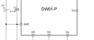
There is no diode between the solar panel and the load, instead there is a Q2 mosfet. The diode in the mosfet allows current to flow from the panel to the load. If a significant voltage appears on Q2, then transistor Q3 opens, capacitor C4 charges, which causes op-amps U2c and U3b to open mosfet Q2. Now, the voltage drop is calculated using Ohm's law, i.e. I*R, and it is much less than if there was a diode there. Capacitor C4 is periodically discharged through resistor R7, and Q2 closes. If current flows from the panel, then the self-inductive emf of inductor L1 immediately forces Q3 to open. This happens very often (many times per second). In the case when current flows to the solar panel, Q2 closes, but Q3 does not open, because diode D2 limits the self-induction emf of inductor L1. Diode D2 can be designed for a current of 1A, but during testing it turned out that such a current rarely occurs.
Trimmer VR1 sets the maximum voltage. When the voltage exceeds 13.8V, the operational amplifier U2d opens mosfet Q1 and the output from the panel is “shorted” to ground. In addition, op-amp U3b disables Q2, etc. the panel is disconnected from the load. This is necessary because Q1, in addition to the solar panel, short-circuits the load and the battery.
N-channel mosfets control
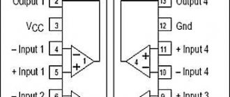
To drive mosfets Q2 and Q4, more voltage is required than that used in the circuit. To do this, op-amp U2 with a string of diodes and capacitors creates an increased voltage VH. This voltage is used to power U3, whose output will be increased voltage. The combination of U2b and D10 ensures the stability of the output voltage at 24 Volts. At this voltage, the voltage through the gate-source of the transistor will be at least 10V, so the heat generation will be small. Typically, N-channel mosfets have much lower resistance than P-channel ones, which is why they were used in this circuit.
Undervoltage protection
Mosfet Q4, operational amplifier U3a with external wiring of resistors and capacitors, are designed for protection against low voltage. Here Q4 is used non-standard. The mosfet diode ensures a constant flow of current into the battery. When the voltage is above the set minimum, the mosfet is open, allowing a small voltage drop when charging the battery, but more importantly, it allows current to flow from the battery to the load if the solar panel cannot provide sufficient power output. The fuse protects against short circuits on the load side.
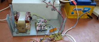
Below are pictures of the arrangement of elements and printed circuit boards.
Device setup
During normal use of the device, jumper J1 should not be inserted! LED D11 is used for tuning. To configure the device, connect an regulated power supply to the “load” terminals.
Installing undervoltage protection Insert jumper J1. In the power supply, set the output voltage to 10.5V. Rotate trimming resistor VR2 counterclockwise until LED D11 lights up. Turn VR2 slightly clockwise until the LED goes out. Remove jumper J1.
Setting the maximum voltage In the power supply, set the output voltage to 13.8V. Rotate trimming resistor VR1 clockwise until LED D9 goes out. Slowly turn VR1 counterclockwise until LED D9 lights up.
The controller is configured. Don't forget to remove jumper J1!
If the power of the entire system is small, then the mosfets can be replaced with cheaper IRFZ34. And if the system is more powerful, the mosfets can be replaced with more powerful IRFZ48.
Discussion of the scheme on the forum
List of radioelements
| Designation | Type | Denomination | Quantity | Note | Shop | My notepad |
| U1 | Voltage reference IC | LM336-2.5 | 1 | Search in the Otron store | To notepad | |
| U2 | Operational amplifier | LM324 | 1 | Search in the Otron store | To notepad | |
| U3 | Operational amplifier | LM358 | 1 | Search in the Otron store | To notepad | |
| Q1, Q2, Q4 | MOSFET transistor | IRFZ44 | 3 | KP723A | Search in the Otron store | To notepad |
| Q3 | Bipolar transistor | BC327 | 1 | KT685A | Search in the Otron store | To notepad |
| D1 | Schottky diode | 1.5KE16 | 1 | Search in the Otron store | To notepad | |
| D2, D4 | Schottky diode | 1N5819 | 2 | KDSh2105V | Search in the Otron store | To notepad |
| D3, D5-D8, D10 | Rectifier diode | 1N4148 | 6 | KD522A | Search in the Otron store | To notepad |
| D9, D11 | Light-emitting diode | 2 | Search in the Otron store | To notepad | ||
| C1, C3 | Electrolytic capacitor | 1000 µF 25 V | 2 | Search in the Otron store | To notepad | |
| C2, C4-C7 | Capacitor | 100 nF | 5 | Search in the Otron store | To notepad | |
| C9 | Electrolytic capacitor | 100 µF 35 V | 1 | Search in the Otron store | To notepad | |
| C8, C10, C12 | Electrolytic capacitor | 10 µF 25 V | 3 | Search in the Otron store | To notepad | |
| C11 | Capacitor | 1 nF | 1 | Search in the Otron store | To notepad | |
| R1, R9, R11, R16, R19 | Resistor | 10 kOhm | 5 | Search in the Otron store | To notepad | |
| R2, R10 | Resistor | 56 kOhm | 2 | Search in the Otron store | To notepad | |
| R3 | Resistor | 1 kOhm | 1 | Search in the Otron store | To notepad | |
| R4, R12 | Resistor | 2.2 MOhm | 2 | Search in the Otron store | To notepad | |
| R5, R8, R13-R15, R18 | Resistor | 100 kOhm | 6 | Search in the Otron store | To notepad | |
| R6 | Resistor | 4.7 kOhm | 1 | Search in the Otron store | To notepad | |
| R7 | Resistor | 1 MOhm | 1 | Search in the Otron store | To notepad | |
| R17, R20 | Resistor | 2.2 kOhm | 2 | Search in the Otron store | To notepad | |
| VR1, VR2 | Trimmer resistor | 10 k | 2 | Search in the Otron store | To notepad | |
| L1 | Throttle | 25 turns of 1 mm wire on a T68-52A core | 1 | Search in the Otron store | To notepad | |
| F1 | Fuse | 25 A | 1 | Search in the Otron store | To notepad | |
| ST1-ST3 | Terminals | 2 contacts | 3 | Search in the Otron store | To notepad | |
| J1 | Connector | PLS-2 | 1 | Search in the Otron store | To notepad | |
| Car battery | 1 | Search in the Otron store | To notepad | |||
| A solar panel | 1 | Search in the Otron store | To notepad | |||
| Add all | ||||||
Original article
Attached files:
- solar_controller.rar (75 KB)
Tags:
- Charger
- Translation