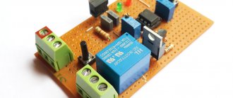
Conventional chargers for car batteries, sold at prices starting from 2,000 rubles, are a simple power supply with a diode bridge and an ammeter for monitoring current. Is it possible to use such a charger for a long time if the price of a new Bosch lead battery reaches 5,000 rubles? Everyone decides for themselves. So the author decided to spend a little money and create a charger that has all the necessary modes for quickly and safely restoring battery capacity.
Description of the charger
- Battery voltage measurement.
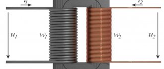
- Measurement of charge and discharge current. The current is measured by a current sensor on the op-amp.
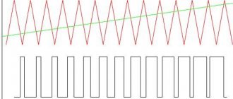
- Stabilization of the charging current at the selected level. The regulator algorithm is step-by-step, current control is PWM (Current is set from the main window of the device.). 3.1 Selecting the charging mode - direct current or pulsating (desulfation).
- Shutting off the charge if the voltage reaches the specified level selected in the menu.
- Stabilization of the discharge current at the selected level in discharge mode. The regulator algorithm is step-by-step, current control is PWM.
- Calculation of Ampere*hours during battery discharge. Discharge is performed only after the battery is fully charged. (When selecting the discharge mode, if the battery is not fully charged, a recharge is automatically performed, and then a discharge with calculation of Ampere*hours.)
- Turn on the display backlight (LIGHT). Menu selection. Parameter Backlight on – the backlight is always on. In auto off mode – the backlight turns on when power is applied for 30 seconds and when the buttons are pressed. After 30 seconds from the last button press, the backlight turns off.
- Whenever the program is stopped, an intermittent signal (0.5 Hz) is sent to pin 4 of the MK. The signal is turned off by pressing the start button.
- The program monitors the correctness of voltage settings. The minimum voltage (Umin) cannot be set higher than or equal to the maximum (Umax). And vice versa.
- In start mode, pressing the PLUS or MINUS button displays current information about the state of the process on the indicator. The top line shows current and voltage. The bottom line shows the remaining time (in detail) and the power output in percentage.
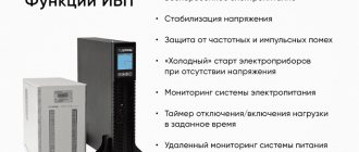
Functions
Controllers are designed for:
- Observations of the charging process. When the capacity is restored from 0 to 10%, the preliminary accumulation of capacity works. From 10 to 70-80% there is an increase in the filling rate with direct current. Recharging is slower due to increased resistance in the circuit.
- Drawdown adjustments. Protects the electrical circuit from short circuits and voltage sags.
- Recharge locks. Each battery has a maximum voltage limit (for Li-Ion it is about 4.2 V). Having reached the specified number, the power is automatically turned off, preventing the battery from swelling and exploding.
- Deep discharge protection. If the battery voltage drops below a critical value (3 V in Li-Ion), the nominal capacity is lost and the battery life is reduced.
- Balancing. Monitors uniform charging of all parts of the electrical circuit, increasing the service life of the battery.
- Temperature observations. When overheating or hypothermia occurs, the thermistor is triggered, which turns off the power supplied to the battery.
All parameters are set to the microcircuit or controller at the production stage.
Scheme and printed circuit boards of the memory
Control block diagram
Power supply circuit
Expert advice
The choice of controller depends on the usage scenario, battery voltage and battery chemistry. With a limited budget, they rely on PWM. MPPT is used to maintain the solar farm. A battery charge controller is supplied to any power source, protecting them from overheating, overcharging, undercharging and loss of capacity. Devices can be integrated or external. The latter are used to obtain energy from solar panels or wind turbines, additionally using an inverter.
Charger operation
1. The program starts/stops by clicking on the start button from any program window. If the button is pressed while the program is running, the device goes into finish mode (ending the program). The next press returns the device to its original state (main indicator window).
2. If the battery voltage is lower than Umax/4, the battery is considered not connected or faulty. The display shows No Bat. In START mode, the name of the selected mode flashes.
Overdischarge protection
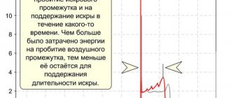
When the voltage reaches critically low values that make the operation of the device itself problematic (usually in the range of 2.3-2.5V), the corresponding MOSFET transistor, which is responsible for supplying current to the mobile phone, is turned off. Next, there is a transition to sleep mode with minimal consumption. And there is a rather interesting aspect of the work. So, until the battery cell voltage exceeds 2.9-3.1 V, the mobile device cannot be turned on to operate in normal mode. You may have probably noticed that when you connect your phone, it shows that it is charging, but it doesn’t want to turn on and function normally.
Charging Mode
The program controls the voltage and current on the battery. If the voltage is lower than the one specified in the Umax settings, the charging current stabilizer operates with the Is setting. If the voltage reaches Umax, the program stops. Indication charge off.
If the voltage rises above Umax by 0.2, the program stops, ERROR is displayed in the top line. In the bottom line is the voltage at which the shutdown occurred.
If the charge current I exceeds the current Is by 0.2 for a time of more than 5 seconds, the program stops, ERROR is displayed.
If the charging time has expired (parameter H, clock), the program stops, ERROR is displayed in the top line. The bottom line says Time out.
Controller selection criteria
The battery charging controller for solar panels is a very important element of the power supply system. The varied range of models can make it a little confusing when choosing a device.
It’s easier to choose the right model if you take into account the following criteria when purchasing:
- Input voltage indicator. This value of the selected device should be higher by approximately 20% of the voltage of the batteries that generate converters of sunlight into current.
- Total battery power value. It should not be higher than the output current.
Modern models have a number of additional features designed to increase safety when using charging process regulators. Devices that control charging and discharging processes may be protected from weather conditions, excessive load, short circuits, overheating, and also from incorrect connection (this concerns non-compliance with polarity). Therefore, you should select a device not only depending on the described criteria, but also taking into account the protection functions that will best ensure the safe operation of the device.
Discharge mode
If at the start of the program the voltage on the battery is below Umax, the battery is recharged with a current Is. After reaching the voltage Umax, the discharge of the battery with current Ii begins. The battery capacity is being calculated.
When the voltage on the battery reaches Umin, the discharge stops, the indicator displays the discharge off and the capacity on the battery -???.?AH Vm 11.0 – the minimum voltage on the battery.
If the recharging or discharging time has expired (time H is set for recharging and charging), the program stops, ERROR is displayed.
If the charge or discharge current exceeds the set value by 0.2, the program stops, ERROR is indicated in the top line. In the bottom line is the current at which the shutdown occurred.
What is a battery charge controller and what is it for?
What is a battery charge controller and what is it for?
Why do you need a charge controller?
A charge controller is a device that automatically regulates the level of current and voltage from a source (such as solar panels) to ensure that batteries are charged, thus protecting the batteries from damage.
Is it possible to do without a charge controller?
Having some experience working with electrical appliances, knowing how to use a voltmeter and ammeter, and having carefully studied the battery instructions for charging and discharging characteristics, you can certainly do without a charge controller.
The battery charge is determined by the voltage between the terminals. There is nothing stopping you from connecting the source (for example, solar panels) directly to the battery, while controlling the voltage values at the terminals and the current from the source (so that the battery is not damaged). When the voltage at the terminals corresponds to the maximum charge, you simply need to turn off the source. This will charge the battery to 60-70% of its maximum capacity. In order to charge it 100%, the battery needs to stabilize - for some time after reaching the maximum voltage, continue charging at this voltage.
With this method of charging the battery, there is a high probability of a decrease in the rated capacity (due to systematic undercharging) or failure due to high current or voltage. This is why various charge controllers are used.
What types of charge controllers are there?
There are mainly three types of charge controllers - on/off controller, PWM (PWM) controller and MPPT (TMM) controllers. What are their features and how do they differ:
on/off charge controller
This device performs the function of disconnecting batteries from the source when a certain voltage is reached. This type of controller is practically not used today. This is the simplest alternative to manually monitoring battery charge, which we talked about earlier.
PWM (PWM) controller
This device is a more advanced option for charging batteries, since it automatically controls the level of current and voltage, and also monitors the onset of maximum voltage. After the maximum voltage is reached, the PWM controller holds it for some time to stabilize the battery and achieve its maximum capacity. Typically, such controllers are inexpensive and can suit simple solar systems.
You can read about how to choose such a controller here –
MPPT (TMM) controllers
This controller is the most modern solution for solar power plants. Solar panels produce power at a strictly defined value of current and voltage (voltage-voltage curve - current-voltage characteristic) - this mode is called the Point of Maximum Power (TPM). The MPPT controller allows you to monitor this point and can use the energy of solar panels most efficiently, which in turn increases the charging rate of the batteries. Such controllers can charge batteries (battery bank) 30-40% more efficiently, therefore, for backup and autonomous solar power plants, the use of such controllers becomes most profitable, despite their high cost relative to PWM controllers.
Which charge controller to choose?
When choosing a controller for a solar system, you first need to understand the scale of the system itself. If you are assembling a small solar system to provide the most necessary household appliances with electricity (from 0.3 kW to 2 kW), then you can get by with a properly selected PWM controller. If we are talking about an autonomous system, a backup system, or, perhaps, a system compatible with network electricity, then in this case you cannot do without a good MPPT controller.
You can also call us at 8-800-100-82-43 or +7-499-7097509 and we will be happy to help you choose a controller according to your needs!
Battery CTC mode
When the program starts, the battery charge with current Is is turned on. After 1 second, the battery switches to a discharge with current Ii. After another 1 second, the battery switches to charging again. This continues until the voltage reaches Umax - the program stops. CTC indication off. If the voltage rises above Umax by 0.2, the program stops, ERROR is displayed. If the charge or discharge current exceeds the set value by 0.2, the program stops, ERROR is displayed.
If the charging time has expired (parameter H), the program stops, ERROR is displayed in the top line. The bottom line says Time out.
The selected mode is not remembered after disconnecting from the network. When turned on, it is always in charging mode.
Types of controllers for solar panels
Ensuring maximum efficiency of solar power plants, which are forced to use either the panels themselves or batteries as an energy source, is a technologically complex and expensive task. For this reason, the choice of controller for the system is made based on the most important factors. These are the potential performance of the SPP, the importance of ensuring maximum efficiency and the expected profit. As a result, you have to compromise, choosing one of five possible options.
We offer the most popular and efficient controllers for solar power plants of various capacities:
- PWM (PWM).
The PWM (Pulse-Width Modulation) solar panel controller is capable of reliably modulating the current value. The result is the ability to recharge the battery completely, albeit over a fairly long period of time. The price of these models for small private power plants is quite reasonable. - MPRT.
It is recommended for owners of stations with sufficiently high power to buy a charge controller for solar panels of the MPPT (Maximum Power Point Tracking) type. In this case, the considerable cost of such a regulator will quickly pay for itself, since it is 30-35% more efficient than any competitor. This is achieved through the operation of a complex computer algorithm, in real time, constantly calculating and delivering current of optimal strength and voltage.
Operating principle of solar controller and battery charging stage:
- Accumulation (Bulk) – charging with maximum current until the specified voltage value is reached at the stage – absorption, in which case the battery becomes 80% infected;
- Absorption or absorption (Absorbtion) is an absorbing charge in which the charge controller maintains the voltage, reducing the charging current until the battery is fully charged;
- Maintenance charge or equilibrium (Float) - reducing the voltage below the absorption stage value to prevent overheating or gas formation;
- Balancing charge or equalization (Equalize) - used only for batteries with liquid electrolyte, during which a higher voltage is applied, air bubbles form on the plates, rising to the top mix the electrolyte. This process is accompanied by the formation of hydrogen and oxygen, which increases its explosiveness. To ensure safe operation of this device, it is sufficient to provide ventilation and eliminate all sources of ignition. This mode cannot be used for sealed batteries.
Tablet device
Real practice of electronics repair
Nowadays you won’t surprise anyone with a computer, much less a tablet. Surely our descendants will believe that tablet PCs appeared before laptops and netbooks. And this is not surprising, because over their modest history, Tablet PCs have gained enormous popularity.
For everyone interested, I suggest you familiarize yourself with the electronic content of a tablet computer.
The Ritmix RMD-825 tablet ended up in my hands. Yes, the model is budget, cheap, but the composition of tablets, as a rule, differs only in the power of the “component”; there is no fundamental difference in the device.
What's inside the tablet?
The Ritmix RMD-825 tablet is easy to open; the two parts of the case are connected with latches. I opened it with a special opener, which is often used when repairing cell phones. Under the cover I found this.
- Display (matrix, screen). In this case TFT. LCD matrices based on thin film transistors (Thin Film Transistor) are very common and cheap. Matrix model – GL080001T0-50 V1 .
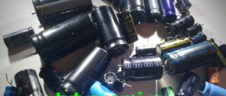
- Li-polymer lithium battery at 3.7V with a capacity of 3000 mAh.
The battery has a built-in charge/discharge controller. I have already talked in more detail about its structure and operating algorithm on the pages of the site.
The printed circuit board requires separate consideration.
CPU
A single-core processor – ALLWINNER TECH A13 (1GHz) – is installed in the center of the printed circuit board. In the photo on the left, the 8-pin chip in the SO8 package is PCF8563T ( 8563T ) - a real time clock ( RTC ) with a built-in calendar. Next to it is a chip ( CF227 ) in the shape of a “cigar” - this is a quartz resonator.
Also not far from the processor you can find a 24 MHz master oscillator chip. Such a small detail, but very important.
ROM
The ROM used is NAND FLASH memory MT29F32G08CBACA (29F32G08CBACA) 32Gb (32 gigabits ) in a 48-pin TSOP package. Nearby on the board there is a seat for another identical chip - apparently for other modifications of the tablet. The chip manufacturer is Micron.
Similar chips are used in solid-state drives (SSD drives) and USB flash drives.
RAM
The “RAM” of the tablet is two H5TQ2G83CFR DDR3 SDRAM memory chips of 2Gb (2 gigabytes ) each. Datasheets for memory chips always indicate memory in bits, not bytes! And to be even more precise, there are 2147483648 bits in this chip. A little more than 2 billion bits. The H5TQ2G83CFR case is BGA, that is, the microcircuits are soldered to the board via solder balls.
Wi-Fi module
Wi-Fi is provided by a USB wireless communication module based on the Realtek RTL8188CUS .
It is connected to the circuit via 6 contacts. 2 of them are the common wire (GND). Next, plus +3.3V power supply and two contacts – USB interface ( USB_DP and USB_DN ). An antenna is connected to the RF pin, which looks like a strangely shaped copper plate.
What it is
The charge controller is one of the electronic devices in the control circuit of solar power plants.
The device monitors the battery charging parameters and regulates the charging process.
The device performs the following functions:
- Turns off the battery when it reaches full charge;
- Disconnects consumers when the charge drops to minimum values;
- Reconnects consumers in case of charge restoration;
- Controls the progress of the charging process;
- Automatically connects energy sources to charge energy storage devices.
The use of controllers allows you to extend the service life of batteries and automate the operation of power plants.
For automatic and safe operation, the devices are equipped with various modes in which they are able to operate in accordance with the specified parameters, and are also equipped with means and protection elements.
These elements include:
- From incorrect polarity on the current source and on the load;
- From short circuits on incoming and outgoing lines;
- From various types of overheating and high voltages.