PWM operating principle
The pulse width modulated signal is generated in two ways:
- analog;
- digital.
With the analog method of creating a PWM signal, the carrier in the form of a sawtooth or triangular signal is supplied to the inverting input of the comparator, and the information input is supplied to the non-inverting input. If the instantaneous carrier level is higher than the modulating signal, then the output of the comparator is zero, if lower – one. The output produces a discrete signal with a frequency corresponding to the frequency of the carrier triangle or saw, and a pulse length proportional to the level of the modulating voltage.
As an example, the pulse width modulation of a linearly increasing triangular signal is given. The duration of the output pulses is proportional to the output signal level.
Analog PWM controllers are also available in the form of ready-made microcircuits, inside of which a comparator and a carrier generation circuit are installed. There are inputs for connecting external frequency-setting elements and supplying an information signal. The signal that controls powerful foreign keys is removed from the output. There are also inputs for feedback - they are needed to maintain the established control parameters. This is, for example, the TL494 chip. For cases where the consumer power is relatively small, PWM controllers with built-in switches are produced. The internal key of the LM2596 chip is designed for current up to 3 amperes.
The digital method is carried out using specialized chips or microprocessors. The pulse length is regulated by an internal program. Many microcontrollers, including the popular PIC and AVR, have a built-in module on board for hardware implementation of PWM; to receive a PWM signal, you need to activate the module and set its operating parameters. If such a module is missing, then PWM can be organized using a purely software method, it is not difficult. This method provides greater capabilities and greater freedom due to flexible use of outputs, but uses more controller resources.
Q: What elements can be included in the power system:
A: Here is a list of the main elements:
- PWM controller. The main element of the power system. It is he who determines the maximum possible number of phases, but not all of them will necessarily be used. The same controller can be used on different models, but with different numbers of phases involved. As an example, I will give the 4-phase Primarion PX3544, which is used on the GeForce 8800 GT (2 phases), GeForce 8800 GTS 512 Mb (3 phases) and GeForce 9800 GTX (all 4 phases) video cards.
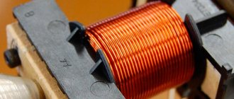
- Chokes (inductors).
- Capacitors.
- Mosfets (MOSFETs).
- Drivers. They can be implemented either as separate chips or integrated into a voltage controller, a DrMOS chip, or even a phase doubling chip. The number of drivers cannot be less than the number of real phases.
- DrMOS chips. They are an assembly of a pair of mosfets (lower + upper) and a driver in one housing. Manufactured by Renesas Electronics, Fairchild Semiconductors, Vishay Siliconix and Infineon Technologies. Used on MSI and (more recently - Gigabyte) motherboards. It can also be found on some reference video cards from NVIDIA and ATI, for example on the GeForce GTX295 (Single PCB) and Radeon HD4770.
- Phase Doublers with integrated drivers. So far I have only come across Intersil ISL6611A and uPI Semiconductor uP6284, which make two from one phase, thus overcoming the voltage controller limitation on the number of maximum supported phases.
PWM signal characteristics
Important characteristics of a PWM signal are:
- amplitude (U);
- frequency (f);
- duty cycle (S) or duty cycle D.
The amplitude in volts is set depending on the load. It must provide the rated supply voltage of the consumer.
The frequency of the pulse width modulated signal is selected based on the following considerations:
- The higher the frequency, the higher the control accuracy.
- The frequency should not be lower than the response time of the device controlled using PWM, otherwise noticeable ripples of the controlled parameter will occur.
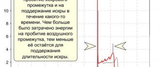
- The higher the frequency, the higher the switching losses. It occurs due to the fact that the key switching time is finite. In the locked state, the entire supply voltage drops across the key element, but there is almost no current. In the open state, the full load current flows through the switch, but the voltage drop is small, since the throughput resistance is a few ohms. In both cases, power dissipation is negligible. The transition from one state to another occurs quickly, but not instantly. During the unlocking and locking process, a large voltage drops on a partially open element and at the same time a significant current flows through it. At this time, power dissipation reaches high values. This period is short, the key does not have time to warm up significantly. But with increasing frequency, such time intervals per unit time become larger, and heat losses increase. Therefore, it is important to use fast elements to build keys.
- When controlling an electric motor, the frequency has to be moved beyond the human audible range - 25 kHz and above. Because at a lower PWM frequency an unpleasant whistle occurs.
These requirements are often in conflict with each other, so the choice of frequency in some cases is a search for a compromise.
The amount of modulation is characterized by the duty cycle. Since the pulse repetition rate is constant, the duration of the period is also constant (T=1/f). A period consists of a pulse and a pause, having a duration of timp and tpause, respectively, and timp+tpause=T. The duty cycle is the ratio of the pulse duration to the period – S=tpulse/T. But in practice it turned out to be more convenient to use the inverse value - the duty cycle: D=1/S=T/timp. It is even more convenient to express the fill factor as a percentage.
How to test a PWM controller
There are several ways to test a PWM controller. You can, of course, do this without a multimeter, but why bother if you can use a normal device.
Read also: How to repair a grinder button
Before checking the operation of the PWM controller, it is necessary to perform basic diagnostics of the power supply itself. It works like this:
Step 1. Carefully inspect the power supply itself, in which the PWM is installed, when turned off. In particular, electrolytic capacitors should be carefully inspected for swelling.
Step 2. Check the fuse and input filter elements of the power supply for serviceability.
Step 3. Check for short circuit or open circuit of the rectifier bridge diodes. You can ring them without desoldering them from the board. In this case, you must be sure that the circuit being tested is not shunted by the transformer windings or resistor. If you suspect this, you will still have to unsolder the elements and check them separately.
Step 4. Check the serviceability of the output circuits, namely electrolytic capacitors of low-frequency filters, rectifier diodes, diode assemblies, etc.
Step 5. Check the power transistors of the high-frequency converter and the transistors of the control cascade. In this case, be sure to check the return diodes that are connected in parallel to the collector-emitter electrodes of the power transistors.
Checking the PWM controller - video instructions:
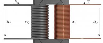
Most modern electronic devices practically do not use analog (transformer) power supplies; they are replaced by pulsed voltage converters. To understand why this happened, it is necessary to consider the design features, as well as the strengths and weaknesses of these devices. We will also talk about the purpose of the main components of pulsed sources and provide a simple example of an implementation that can be assembled with your own hands.
LED driver lifespan.
There is no specific service life as such, but many manufacturers are willing to provide a five-year warranty on their products. Naturally, upon coordination of capacities. In order for the power source to last longer, you should not provide a load at which it will deliver maximum currents. If it is assembled from high-quality components, it will work stably for quite a long time. But operating temperatures can be close to critical (depending on circuit design solutions). It is optimal if the power of consumers is 20-30 percent less.
If we are talking about homemade production, then a lot depends on the quality of the assembly and the quality of the radio components. It is advisable to attach integral stabilizers to a radiator to ensure thermal conditions; do not forget about the heat-conducting paste between the stabilizer body and the heat sink.
- Related Posts
- Incandescent lamp: characteristics and features.
- Installation and connection of street road lighting
- How to properly use emergency lighting with all current standards and requirements
Fill factor
One of the parameters of any rectangular signal is the duty cycle.
For most square waveforms it is 50%, which is fine, but the waveforms do not have to be symmetrical. The time of the “open” (on) state can vary from completely off to completely on, from 0% to 100%, and can take any value throughout the entire range. Examples of fill factor of 10%, 50% and 90% are shown below. Although the frequencies of the signals are the same, this is not a requirement.
Figure 1 – Examples of PWM signals
The reason for the popularity of PWM is simple. For many loads, such as resistors, the response is proportional to the power input. That is, the conversion between them is simple. But, for example, LEDs have a very non-linear response to current; by applying half of its rated current to the LED, you will still get more than half the luminous flux that the LED can emit. With PWM, the level of light produced by the LED is very linear. Motors, which will be discussed later, also respond well to PWM.
One of several ways to obtain a PWM signal is to use a ramp and a comparator. As shown below, a sawtooth (or triangle) waveform does not have to be symmetrical, but linearity of the waveform is important. The frequency of the ramp wave corresponds to the sampling frequency of the signal.
Figure 2 – PWM modulator. And why the symmetry of the waveform slopes does not matter.
If no calculations are required, then PWM can be fast. The limiting factor is the frequency response of the comparator. This may not be a problem since basic applications use fairly low speeds. Some microcontrollers have built-in PWM and can record or create the necessary signals.
The scope of use of PWM is quite wide. PWM is the heart of Class D amplifiers, where by increasing the voltage you increase the maximum output power, and the PWM frequency is chosen beyond the limits of human hearing (typically 44 kHz). The speakers do not respond to high frequencies but echo low frequencies, which are audio signals. For even greater accuracy, higher sampling rates can be used; 100 kHz or more are also inaudible.
Figure 3 – How an audio signal modulates a PWM signal
Another popular application of PWM is motor speed control. Motors, as a class of loads, require very high currents to operate. The ability to change their speed using PWM greatly improves the efficiency of the entire system. PWM is more effective at controlling engine speed at low speeds than linear methods.
The essence of PWM
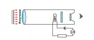
The abbreviation PWM stands for Pulse Width Modulation. This definition applies to electrical and electronics engineering. But the physical phenomenon that underlies PWM has always existed. We are talking about the inertia of heat propagation in various environments. The simplest and most obvious example is potatoes baked in a fire. A hot potato is tossed from hand to hand the more often the hotter it is. Thereby reducing the flow of heat from the potato to the hand and preventing burns.
Pulse width is a time value. And if this impulse characterizes a change in energy, its effective value is equivalent to the area limited by the impulse line. For example, a square pulse is related to height (amplitude) and width (time). Therefore, the same area, and, consequently, the amount of energy, can be obtained either by decreasing the amplitude and increasing the pulse width, or vice versa, by increasing the amplitude and decreasing the time (width).
Pulse width control WID
In Western literature, there is practically no distinction between the concepts of pulse-width regulation of WID and pulse-width modulation of PWM. However, we still have a difference between them.
Nowadays, many microcircuits, especially those used in DC-DC converters, implement the WID principle. But at the same time they are called PWM controllers. Therefore, now there is practically no difference in name between these two methods.
In any case, to form a certain pulse duration supplied to the base of the transistor and opening the latter, reference and reference voltage sources, as well as a comparator, are used. Consider a simplified circuit in which the battery GB supplies the consumer Rн in a pulsed manner through the transistor VT. I’ll say right away that in this circuit I specifically did not use such elements necessary for the operation of the circuit: a capacitor, an inductor and a diode. This is done to simplify the understanding of the operation of the PWM, and not the entire converter.
To put it simply, a comparator has three terminals: two inputs and one output. The comparator works as follows. If the voltage value at the “+” input pin (non-inverting input) is higher than at the “-” input (inverting input), then the output of the comparator will be a high level signal. Otherwise - low level.
In our case, it is the high level signal that opens the transistor VT. Let's consider how the required pulse time duration ti is formed. To do this, we will use the following graph.
With WID, a sawtooth signal of a given frequency is supplied to one input of the comparator. It is also called the support. The second input is supplied with a reference voltage, which is compared with the reference voltage. As a result of the comparison, a pulse of the appropriate duration is formed at the output of the comparator.
If there is a reference signal at the non-inverting input of the comparator, then there will be a pause first, and then a pulse. If a master signal is applied to the non-inverting input, there will first be a pulse, then a pause.
Thus, by changing the value of the specified signal, you can change the duty cycle, and, accordingly, the average voltage at the load.
They strive to make the frequency of the reference signal maximum in order to reduce the parameters of the chokes and capacitors (not shown in the diagram). The latter leads to a reduction in the weight and dimensions of the switching power supply.
How does an inverter work?
RF modulation can be done in three ways:
- pulse-frequency;
- phase-pulse;
- pulse width.
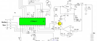
In practice, the last option is used. This is due both to the simplicity of implementation and to the fact that PWM has a constant communication frequency, unlike the other two modulation methods. A block diagram describing the operation of the controller is shown below.
Block diagram of a PWM controller and oscillograms of the main signals
The operating algorithm of the device is as follows:
The reference frequency generator generates a series of rectangular signals, the frequency of which corresponds to the reference one. Based on this signal, a sawtooth UP is formed, which is supplied to the input of the PWM comparator. The signal UUS coming from the control amplifier is supplied to the second input of this device. The signal generated by this amplifier corresponds to the proportional difference between UП (reference voltage) and UРС (control signal from the feedback circuit). That is, the control signal UUS is, in fact, a mismatch voltage with a level that depends on both the current across the load and the voltage across it (UOUT).
Read also: Bed for hydraulic press
This implementation method allows you to organize a closed circuit that allows you to control the output voltage, that is, in fact, we are talking about a linear-discrete functional unit. Pulses are generated at its output, with a duration depending on the difference between the reference and control signals. Based on it, a voltage is created to control the key transistor of the inverter.
The process of stabilizing the output voltage is carried out by monitoring its level; when it changes, the voltage of the control signal UPC changes proportionally, which leads to an increase or decrease in the duration between pulses.
As a result, the power of the secondary circuits changes, which ensures stabilization of the output voltage.
To ensure safety, galvanic isolation between the power supply and feedback is necessary. As a rule, optocouplers are used for this purpose.