General concept
A capacitor consists of two conductive plates and a dielectric between them. And that's it, nothing more. It looks like a simple radio component, but it works differently at high and low frequencies.
Indicated on the diagram by two parallel lines.
Principle of operation
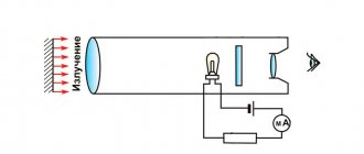
This radio component demonstrates well the phenomenon of electrostatic induction. Let's look at it with an example.
If you connect a constant current source to the capacitor, then at the initial moment of time the current will begin to accumulate on the plates of the capacitor. This occurs due to electrostatic induction. Resistance is practically zero.
The electric field, due to electrostatic induction, attracts opposite charges to two opposite plates. This property of matter is called capacity. All materials have a capacity. And even for dielectrics, but for conductors it is much greater. Therefore, the capacitor plates are made of conductor.
The larger the capacitance, the more charges can accumulate on the capacitor plates, i.e. electric current.
The main property of a capacitor is capacitance. It depends on the area of the plates, the distance between them and the dielectric material that fills the space between the plates.
As charges accumulate, the field begins to weaken and the resistance increases. Why is this happening? There is less and less space on the plates, like charges on them act on each other, and the voltage on the capacitor becomes equal to the current source. This resistance is called reactive or capacitive. It depends on the frequency of the current, the capacitance of radio components and wires.
When there is no room left on the plates for the electric current, the current in the circuit will stop. Electrostatic induction disappears. Now there remains an electric field that holds the charges on its plates and does not let them go. And the electric current has nowhere to go. The voltage across the capacitor will become equal to the emf (voltage) of the current source.
What happens if you increase the EMF (voltage) of the current source? The electric field will begin to put more and more pressure on the dielectric, since there is no more space on the plates. But if the voltage on the capacitor exceeds the permissible limits, the dielectric will break through. And the capacitor will become a conductor, the charges will be released, and the current will flow through the circuit. How then to use a capacitor for high voltages? You can increase the size of the dielectric and the distance between the plates, but this reduces the capacitance of the part.
Between the plates there is a dielectric that prevents the passage of direct current. This is precisely the barrier to direct current. Because constant current also creates constant voltage. And a constant voltage can create electrostatic induction only when the circuit is closed, that is, when the capacitor is charging.
This way the capacitor can store energy until a consumer connects to it.
Capacitor and DC circuit
Let's add a light bulb to the diagram. It will only light up while charging.
Another important feature is that when the current charging process occurs, the voltage lags behind the current. The voltage seems to catch up with the current, since the resistance increases smoothly as it charges. Electrical charges take time to move to the capacitor plates. This is the charging time. It depends on capacitance, frequency and voltage.
As it charges, the light begins to glow dimmer.
The light goes out when fully charged.
Direct electric current does not pass through the capacitor until it is charged.
AC circuit
What if you change the polarity on the current source? Then the capacitor will begin to discharge and charge again as the polarity of the source changes.
Electrostatic induction occurs constantly if the electric current is alternating. Every time the current begins to change its direction, the process of charging and discharging begins.
Therefore, the capacitor passes alternating electric current.
The higher the frequency, the lower the reactance (capacitive) resistance of the capacitor.
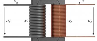
§16. Transformation of energy in electrical and magnetic phenomena
16.4 Charging a capacitor from a source of constant EMF.
The process of charging a capacitor, discussed in the previous section, by transferring charge from one plate to another, is of exclusively theoretical interest, as a method for calculating the energy of a capacitor. In reality, capacitors are charged by connecting them to an EMF source, for example, to a galvanic battery.
Let a capacitor of capacitance C be connected to a source whose emf is equal to ε
(Fig. 145).
The complete electrical connection of the circuit (including the internal resistance of the source) will be denoted
by
R. When the key is closed, an electric current will flow in the circuit, due to which an electric charge will accumulate on the capacitor charges. According to Ohm's law, the sum of the voltages across the capacitor \(~U_C = \frac{q}{C}\) and resistor \(U_R = IR\) is equal to the source emf \(\varepsilon = U_C + U_R\), which leads to the equation \ (~IR = \varepsilon - \frac{q}{C}\) .
(1) In this equation, the capacitor charge and current depend on time. The rate of change of capacitor charge is by definition equal to the current in the circuit \(~I = \frac{\Delta q}{\Delta t}\), which allows us to obtain an equation describing the change in capacitor charge over time
\(~R \frac{\Delta q}{\Delta t} = \varepsilon — \frac{q}{C}\) . (2)
You can also obtain an equation that directly describes the change in current in a circuit over time. To do this, based on equation (1), we write the equations for small changes in input quantities
\(~\Delta \varepsilon = \Delta (IR) + \Delta \left (\frac{q}{C} \right )\) .
Formally, this operation can be described as follows: equation (1) should be written for two moments of time t
and (
t
+ Δ
t
), and then subtract the first from the second equation.
Since the source EMF is constant, its change is zero Δ ε
= 0, the circuit resistance and capacitance of the capacitor are constant, so they can be taken out of the sign of the change Δ, so the resulting equation takes the form
\(~R \Delta I = - \frac{ 1}{C} \Delta q\) .
Finally, we divide it by the period of time during which these changes occurred, as a result we obtain the desired equation (taking into account the relationship between the current strength and charge changes)
\(~\frac{\Delta I}{\Delta t} = -\frac{1}{RC} I\) . (3)
The mathematical meaning of this equation indicates that the rate of decrease in current is proportional to the strength of the current itself. To uniquely solve this equation, it is necessary to set the initial condition - the value of the current at the initial moment of time I
0 = I(0).
We became acquainted with equations of this type in the “mathematical digression”, so here we will analyze it briefly. At the initial moment of time, when the charge of the capacitor is zero, the rate of charge increase (that is, the current strength) is maximum and equal to \(~I_0 = \Delta \left (\frac{\Delta q}{\Delta t} \right )_0 = \frac{\varepsilon}{R}\). Then, as the charge accumulates, the current strength will decrease, when the voltage on the capacitor becomes equal to the source emf, the capacitor charge reaches the maximum stationary value \(~\overline{q} = C\varepsilon\) and the current in the circuit will stop.
Schematically, the time dependences of the capacitor charge and current in the circuit are shown in Fig. 146. To estimate the charging time of a capacitor, we can assume that the charge increases to a maximum value at a constant rate equal to the current strength at the initial time. In this case
\(~\tau = \frac{\overline{q}}{I_0} = RC\) . (4)
A similar estimate of the disappearance of the current, obtained on the basis of equation (3), leads to the same result.
Strictly speaking, the charging time of the capacitor described by equation (2) is equal to infinity. This paradox can be eliminated if we take into account the discreteness of the electric charge. In addition, the charge of a capacitor connected to the battery changes randomly over time and fluctuates, so the equation under consideration describes some average characteristics of the process. However, the resulting estimate of the RC time is widely used in approximate calculations; it is often simply called the capacitor charging time
.
Let us now consider the transformations of various forms of energy in this process. It is clear that the cause of the current in the circuit and, as a consequence, the charging of the capacitor are external forces from the source. At first glance, the energy balance includes a certain contradiction: if the source imparted a charge q
, then the external forces performed work
A
0 =
qε
, and the energy of the capacitor became equal to \(~W = \frac{q^2}{2C} = \frac{q \varepsilon}{2}\) , which in two times less work done by the source.
The contradiction disappears if we take into account that during the charging process an electric current flows through the circuit, therefore a certain amount of heat is released at the resistor, that is, part of the source energy is converted into heat. Let's mentally divide the charging time into small intervals Δ t
i (
i
= 1,2,3...).
Let's rewrite equation (1) in the form \(~\varepsilon = IR + \frac{q}{C}\) , (5)
and multiply it by the value of a small portion of charge transferred over a short period of time Δ t
i, Δ
q
i =
I
iΔ
t
i .
As a result, we obtain \(~\varepsilon \Delta q_i = I_i R \Delta q_i + \frac{q_i}{C} \Delta q_i\) .
(6) Here we denote q
i is the charge of the capacitor before transferring the portion of charge under consideration.
Each member of the resulting equation has a clear physical meaning: \[~\varepsilon \Delta q_i = \delta A\] - the work of external forces to move a portion of the charge Δ q
i;
\[~\frac{q_i}{C} \Delta q_i = \Delta W_C\] - increase in the energy of the capacitor when its charge increases by Δ q
i;
\[~I_i R \Delta q_i = I^2_i R \Delta t_i = \delta Q\] - the amount of heat released on the resistor when a portion of charge Δ q
i flows.
Thus, the law of conservation of energy, expressed by the balance equation (6) for a short period of time turns out to be fulfilled, therefore, it will be fulfilled for the entire charging process. Let's sum up expression (5) over all charging time intervals, resulting in: \[~\sum_i \varepsilon \Delta q_i = \varepsilon \overline{q} = A\] - the total work of external forces to transfer an electric charge equal to the stationary one capacitor charge; \[~\sum_i \frac{q_i}{C} \Delta q_i = \frac{\overline{q^2}}{2C} = \frac{\varepsilon \overline{q}}{2} = \frac{ C\varepsilon^2}{2}\] is the energy of a charged capacitor;
finally, \(~\sum_i I_i R \Delta q_i = \sum_i I^2_i R \Delta t_i\) is the amount of heat released by the resistor.
Taking into account equation (3) and the formulas from the “mathematical digression”, the last sum can be expressed as
\(~Q = R \sum_i I^2_i \Delta t_i = R \frac{1}{2} I^2_0 \tau = R \frac{1}{2} \left ( \frac{\varepsilon}{R } \right )^2 RC = \frac{C \varepsilon^2}{2}\) . (6)
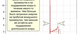
This amount can be calculated graphically. Formula (1) specifies the dependence of the voltage across the resistor \(U_R = IR\) on the charge of the capacitor. This dependence is linear; its graph (Fig. 147) is a straight line segment. q will flow through the resistor
i, this will release the amount of heat \(~\delta Q_i = I_i R \Delta q_i\), which is numerically equal to the area of the narrow strip highlighted in the figure.
The total amount of heat released during the passage of the entire charge is numerically equal to the area of the triangle under the graph of the dependence U
R(
q
), that is,
\(~Q = \frac{1}{2} C \varepsilon \cdot \varepsilon = \frac{C \ varepsilon^2}{2} = \frac{q^2_0}{2 C}\) .
(7) Thus, the energy balance is completely convergent for the entire process: the work done by the source is equal to the sum of the energy of the capacitor and the amount of heat released \(A = W_C + Q\). The energy conversion in this process is shown schematically in Fig. 148.
It is interesting to note that the amount of heat released during charging does not depend on the resistance of the circuit and is exactly equal to the energy of the capacitor. That is, half of the source energy is converted into electric field energy, and the second into thermal energy released in the circuit: nature requires a kind of fifty percent tax in the form of thermal losses, regardless of the resistance of the circuit and the capacitance of the capacitor[1].
Purpose and functions of capacitors
The capacitor plays a huge role in both analog and digital technology. They are electrolytic and ceramic, and differ in their properties, but not in their overall concept. Examples of using:
- Filters high-frequency interference;
- Reduces and smoothes pulsations;
- Separates the signal into constant and variable components;
- Accumulates energy;
- Can be used as a voltage reference;
- Creates resonance with the inductor to amplify the signal.
Examples of using
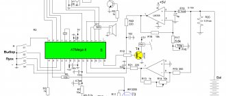
In amplifiers they are usually used to protect subwoofers, power filtering, thermal stabilization and separation of DC and AC components. And electrolytic ones in autonomous circuits with microcontrollers can provide power for a long time due to their large capacity.
In this circuit, transistor VT1 is constantly open to amplify the sound without distortion. But if the input gets stuck or a direct current flows into it, the transistor will open, go into saturation and overheat. To prevent this, you need a capacitor. C1 allows you to separate the constant component from the variable. The alternating signal easily passes to the base of the transistor, but the constant signal does not.
C2, together with resistor R3, performs the function of thermal stabilization. When the amplifier is running, the transistor gets hot. This may introduce distortion into the signal. Therefore, resistor R3 helps maintain the operating point when heating. But when the transistor is cold and stabilization is not required, a resistor can reduce the power of the amplifier. Therefore, C2 comes into play. It conducts the amplified signal through itself by shunting a resistor, thereby not reducing the rated power of the circuit. If its capacitance is lower than designed, it will begin to introduce phase distortion into the output signal.
For the scheme to work well, good nutrition is a must. When a circuit consumes more current at peak values, it is always a heavy load on the power supply. C3 filters power interference and helps reduce the load. The larger the capacitance, the better the sound, but up to certain values, it all depends on the circuit.
And the power supplies use the same principle as in the previous power supply scheme, but here the capacity is needed much more. In this circuit, the capacitance of the electrolyte can be either 1000 μF or 10,000 μF.
You can also connect ceramic capacitors in parallel to the diode bridge, which will bypass the circuit from high-frequency interference and noise from the 220 V network.
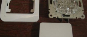
What does a capacitor consist of?
Any capacitor consists of two or more metal plates that do not touch each other. For a more complete understanding of how all this works in a capacitor, let's imagine a pancake.
spread it with condensed milk
and put the exact same pancake on top
The condition must be met: these two pancakes must not touch each other. That is, the top pancake should lie on the condensed milk and not touch the bottom pancake. Here, I think, everything is clear. Here is a typical “pancake capacitor” :-). This is how all capacitors are designed, only thin metal plates are used instead of pancakes, and various dielectrics are used instead of condensed milk. The dielectric can be air, paper, electrolyte, mica, ceramics, and so on. Wiring is connected to each metal plate - these are the leads of the capacitor.
Schematically it all looks something like this.
As you may have noticed, due to the dielectric, the capacitor cannot conduct current. But this applies only to direct current. The capacitor passes alternating current through itself without problems with a small resistance, the value of which depends on the frequency of the current and the capacitance of the capacitor itself.