What is a capacitor
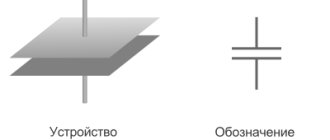
Collecting electricity is the main purpose of a capacitor. Typically this is a system of two insulated conductors located as close to each other as possible. The space between the conductors is filled with a dielectric. The charge accumulated on the conductors is chosen to be opposite. The property of opposite charges to attract each other contributes to its greater accumulation. The dielectric has a dual role: the greater the dielectric constant, the greater the electrical capacity; charges cannot overcome the barrier and be neutralized.
Electrical capacity is the main physical quantity characterizing the ability of a capacitor to accumulate charge. The conductors are called plates; the electric field of the capacitor is concentrated between them.
The energy of a charged capacitor, apparently, should depend on its capacitance.
Electrical capacity
The energy potential makes it possible to use (high electrical capacity) capacitors. The energy of a charged capacitor is used when it is necessary to apply a short-term current pulse.
What quantities does electrical capacity depend on? The process of charging a capacitor begins with connecting its plates to the poles of a current source. The charge accumulated on one plate (the value of which is q) is taken as the charge of the capacitor. The electric field concentrated between the plates has a potential difference U.
Electrical capacity (C) depends on the amount of electricity concentrated on one conductor and the field voltage: C = q/U.
This value is measured in F (farads).
The capacity of the entire Earth cannot be compared with the size of which is approximately the size of a notebook. The accumulated powerful charge can be used in technology.
However, it is not possible to accumulate an unlimited amount of electricity on the plates. When the voltage increases to the maximum value, breakdown of the capacitor may occur. The plates are neutralized, which can lead to damage to the device. The energy of the charged capacitor is completely used to heat it.
Production of electrolytic capacitors
Metals whose oxides are characterized by rectifying properties were called valve metals by analogy with semiconductor diodes. It is easy to guess that oxidation leads to the formation of a material with n-type conductivity. This is considered the main condition for the existence of a valve metal. Of the above, only two have pronounced positive properties:
- Aluminum.
- Tantalum.
Production of electrolytic capacitors.
Aluminum capacitors are used much more often, due to their relative cheapness and prevalence in the Earth's crust. Tantalum is used in extreme cases. The growth of the oxide film occurs in two ways:
- The first technique is to maintain a constant current. As the oxide thickness increases, the resistance increases. Consequently, a rheostat is connected in series with the capacitor during molding. The process is controlled by the voltage drop across the Schottky junction; if necessary, the shunt is adjusted so that the parameters remain constant. The molding speed at the initial stage is constant, then an inflection point occurs with a decrease in the parameter; after a certain interval, further growth of the oxide film occurs so slowly that the technological cycle is considered complete. At the first bend, the anode often begins to spark. Accordingly, the voltage present is called similarly. At the second point, the sparking sharply increases, and further molding process is impractical. And the second bend is called maximum stress.
- The second technique for forming the oxide layer comes down to maintaining a constant voltage at the anode. In this case, the current decreases exponentially. The voltage is chosen below the sparking voltage. The process continues until the residual forward current is reached, below which the level no longer falls. Then the molding ends.
It will be interesting➡ Capacitor - in simple words about the complex
The correct selection of electrolyte plays a major role in the molding process. In industry, this comes down to studying the interaction of aggressive environments with aluminum:
- Representatives of the first group of electrolytes, which include boric, citric acid and borax, almost do not dissolve aluminum and oxide. They are widely used in the production of electrolytic capacitors. Long-term molding leads to a voltage drop to 1500 V, which determines the thickness of the dielectric layer.
- Chromic, sulfuric, succinic and oxalic acids dissolve aluminum oxide well, but do not affect the metal. A distinctive feature of the molding is a relatively thick layer of dielectric. Moreover, with further increase, there is no significant decrease in current or increase in voltage. This process is used to form electrical capacitors with relatively low performance characteristics (up to 60 V). Hydrates and salts of the acid used are mixed with aluminum oxide in porous structures. These processes can be used for protective purposes. Then the molding proceeds according to the previous scheme (first group), and is completed according to the described one. A protective layer of hydroxides protects the oxide from destruction during operation.
- The third group of electrolytes includes predominantly hydrochloric acid. These substances are not used during the molding process; they dissolve aluminum and its salts well. But they are readily used for cleaning surfaces.
For tantalum and niobium, all electrolytes fall under the first group classification. The capacitance value of the capacitor is determined primarily by the voltage at which molding is completed. Polyhydric alcohols, glycerin and ethylene glycol, and salts are used in a similar way.
Not all processes follow the scheme described above. For example, when forming aluminum in a sulfuric acid solution using the direct current method, the following areas are distinguished on the graph:
- A rapid increase in voltage is observed for several seconds.
- Then, at the same rate, there is a decline to a level of about 70% of the peak achieved.
- During the third stage, a thick porous oxide layer grows, and the voltage increases extremely slowly.
- In the fourth section, the voltage increases sharply until spark breakdown occurs. Forming ends.
A lot depends on technology. The thickness of the layer, and therefore the operating voltage and durability of the capacitor, is affected by the electrolyte concentration, temperature, and other parameters.
Energy value
Heating of the capacitor occurs due to the conversion of the electric field energy into internal energy. The ability of a capacitor to do work to move a charge indicates the presence of a sufficient supply of electricity. To determine how great the energy of a charged capacitor is, consider the process of discharging it. Under the influence of an electric field of voltage U, a charge of magnitude q flows from one plate to another. By definition, the work of the field is equal to the product of the potential difference and the amount of charge: A=qU. This relationship is valid only for a constant voltage value, but during the discharge process on the capacitor plates it gradually decreases to zero. To avoid inaccuracies, let's take its average value U/2.
From the formula for electrical capacity we have: q=CU.
From here, the energy of a charged capacitor can be determined by the formula:
We see that its value is greater, the higher the electrical capacity and voltage. To answer the question of what the energy of a charged capacitor is, let us turn to their varieties.
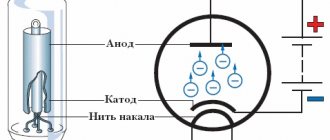
Maximum voltage on the oscillating circuit capacitor
The main device that determines the operating frequency of any alternating current generator is the oscillating circuit. The oscillatory circuit (Fig. 1) consists of an inductor L (consider the ideal case when the coil has no ohmic resistance) and a capacitor C and is called closed. The characteristic of a coil is inductance, it is designated L and measured in Henry (H), a capacitor is characterized by capacitance C, which is measured in farads (F).
Let at the initial moment of time the capacitor be charged in such a way (Fig. 1) that on one of its plates there is a charge +Q, and on the other there is a charge –Q. In this case, an electric field with energy is formed between the plates of the capacitor
, (1)
where is the amplitude (maximum) voltage or potential difference across the capacitor plates.
After closing the circuit, the capacitor begins to discharge and an electric current flows through the circuit (Fig. 2), the value of which increases from zero to the maximum value. Since a current of variable magnitude flows in the circuit, a self-inductive emf is induced in the coil, which prevents the capacitor from discharging. Therefore, the process of discharging the capacitor does not occur instantly, but gradually. At each moment of time, the potential difference across the capacitor plates
(2)
(where is the charge of the capacitor at a given time) is equal to the potential difference across the coil, i.e. equal to the self-induction emf
. (3)
| Fig.1 | Fig.2 |
When the capacitor is completely discharged and , the current in the coil will reach its maximum value (Fig. 3). The induction of the magnetic field of the coil at this moment is also maximum, and the energy of the magnetic field will be equal to
. (4)
Then the current begins to decrease, and the charge will accumulate on the capacitor plates (Fig. 4). When the current decreases to zero, the charge on the capacitor will reach its maximum value Q, but the plate, previously positively charged, will now be negatively charged (Fig. 5). Then the capacitor begins to discharge again, and the current in the circuit flows in the opposite direction.
So the process of charge flowing from one capacitor plate to another through the inductor is repeated again and again. They say that electromagnetic oscillations occur in the circuit. This process is associated not only with fluctuations in the amount of charge and voltage on the capacitor, the current strength in the coil, but also with the transfer of energy from the electric field to the magnetic field and vice versa.
| Fig.3 | Fig.4 |
Recharging the capacitor to the maximum voltage will occur only if there is no energy loss in the oscillatory circuit. Such a contour is called ideal.
In real circuits the following energy losses occur:
1) heat losses, because R¹0;
2) losses in the dielectric of the capacitor;
3) hysteresis losses in the coil core;
4) radiation losses, etc. If we neglect these energy losses, then we can write that, i.e.
. (5)
Oscillations occurring in an ideal oscillatory circuit in which this condition is met are called free, or natural, oscillations of the circuit.
In this case, the voltage U (and charge Q) on the capacitor changes according to the harmonic law:
, (6)
where n is the natural frequency of the oscillatory circuit, w = 2pn is the natural (circular) frequency of the oscillatory circuit. The frequency of electromagnetic oscillations in the circuit is defined as
or . (7)
Period T – the time during which one complete oscillation of the voltage on the capacitor and the current in the circuit occurs is determined by Thomson’s formula
. (8)
The current strength in the circuit also changes according to the harmonic law, but lags behind the voltage in phase by . Therefore, the dependence of the current strength in the circuit on time will have the form
. (9)
Figure 6 shows graphs of changes in voltage U on the capacitor and current I in the coil for an ideal oscillating circuit.
In a real circuit, the energy will decrease with each oscillation. The amplitudes of the voltage on the capacitor and the current in the circuit will decrease; such oscillations are called damped. They cannot be used in master oscillators, because The device will work at best in pulse mode.
| Fig.5 | Fig.6 |
To obtain undamped oscillations, it is necessary to compensate for energy losses at a wide variety of operating frequencies of devices, including those used in medicine.
Didn't find what you were looking for? Use the search:
Best sayings:
A student is a person who constantly postpones the inevitable.
10616 – | 7341 – or read all.
91.146.8.87 © studopedia.ru Not the author of the materials posted. But it provides free use. Is there a copyright violation? Write to us | Feedback.
Disable adBlock! and refresh the page (F5)
very necessary
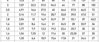
An ideal oscillating circuit consists of a capacitor with a capacity of 1 μF and an inductor. Free electromagnetic oscillations occur in the circuit. The table shows the dependence of energy W
, stored in the capacitor of an ideal oscillatory circuit, from time
t
.
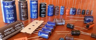
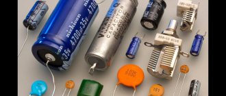
Types of capacitors
Since the energy of the electric field concentrated inside the capacitor is directly related to its capacitance, and the operation of capacitors depends on their design features, various types of storage devices are used.
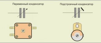
- According to the shape of the plates: flat, cylindrical, spherical, etc.
- By changing the capacitance: constant (the capacitance does not change), variable (by changing the physical properties, we change the capacitance), tuning. Capacitance can be changed by changing temperature, mechanical or electrical. The capacitance of tuning capacitors changes by changing the area of the plates.
- By dielectric type: gas, liquid, solid dielectric.
- By type of dielectric: glass, paper, mica, metal-paper, ceramic, thin-layer films of various compositions.
Depending on the type, other capacitors are also distinguished. The energy of a charged capacitor depends on the properties of the dielectric. The main quantity is called dielectric constant. Electrical capacity is directly proportional to it.
Electrolytic capacitor design
The facings are usually not flat. For electrolytic capacitors, they are often rolled into a tube or a spiral. The cut resembles a Tesla coil with the ensuing consequences. This means that the capacitor has significant inductive reactance, which in this context is considered parasitic. Electrolyte-impregnated paper or fabric is placed between the plates. The body is made of aluminum - the metal is easily covered with a protective layer, is not affected by the electrolyte and removes heat well (remember the active component of the anode resistance).
The device of an electrolytic capacitor.
These are capacitors with dry electrolyte. Their key advantage is decent use of volume. There is no excess electrolyte, which reduces weight and dimensions with the same electrical capacity. Despite the characteristic name, the electrolyte here is not dry, but rather viscous. It impregnates fabric or paper gaskets located between the covers. Due to the viscosity of the electrolyte, the housing can be made of plastic or paper; a resin seal is used for sealing. As a result, the technological cycle of product manufacturing is simplified. Historically, varieties with dry electrolyte appeared later. In domestic practice, the first mentions were made in 1934.
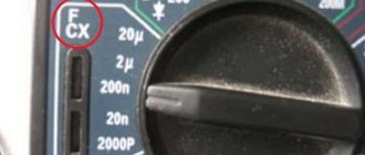
At the end of foreign electrolytic capacitors there are notches made with a cross, through which the internal volume is squeezed out. This is in case of an accident. Such a damaged capacitor can be easily noticed with the naked eye and replaced in time, which speeds up repairs. Marking the housing helps to avoid accidents and incorrect switching polarity. The cathode on imported ones has a white stripe along the entire height with placed minuses, while on domestic ones there are crosses (pluses) on the opposite side.
To increase emissivity, the body color is dark. Exceptions to the rule are rare. This measure increases heat transfer to the environment. When the voltage at the working (forming) voltage is exceeded, a sharp increase in current occurs due to ionization, strong sparking develops at the anode, and the dielectric layer partially breaks through. The consequences of such phenomena are easily eliminated in the design and with the housing used as a cathode: capacitors with liquid electrolyte take up a relatively large amount of space, but remove heat well. But they manifest themselves perfectly when working at low frequencies. Which determines the specific use of power supplies (50 Hz) as filters.
These cylindrical electrolytic capacitors are constructed differently from the one shown above, without the paper inserts. In some models, the housing plays the role of a cathode, the anode is located inside, it can be of any shape so as to ensure the maximum rated capacity. Due to mechanical processing and chemical etching, designed to increase the surface area of the electrode, the parameters can be increased by an order of magnitude. The design is typical for models with liquid electrolyte. The capacitance of the design under consideration varies when produced by industry from 5 to 20 μF at an operating voltage of 200 - 550 V. Due to the increase in electrolyte resistance with decreasing temperature, capacitors with a liquid electrolyte and a housing as a cathode are used mainly in warm microclimates.
An electrolytic capacitor is the least reliable radio component; it is most often the reason for the inoperability of an electrical device. Sometimes the faulty state of a given element is determined visually, but more often it is necessary to use special methods.
Energy of a parallel plate capacitor
We see that the capacitance of the capacitor is directly proportional to the total area of one plate and inversely proportional to the distance between them. The proportionality coefficient is the electrical constant ε 0. An increase in the dielectric constant of the dielectric will increase the electrical capacity. Reducing the plate area makes it possible to obtain tuning capacitors. The energy of the electric field of a charged capacitor depends on its geometric parameters.
We use the calculation formula: W = CU 2 /2.
The energy of a charged flat capacitor is determined using the formula:
W = εε 0 SU 2 /(2d).
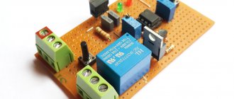
Using capacitors
The ability of capacitors to smoothly collect electrical charge and release it quickly enough is used in various fields of technology.
Connection with inductors allows you to create oscillatory circuits, current filters, and feedback circuits.
Photoflashes and stun guns, in which an almost instantaneous discharge occurs, use the ability of a capacitor to create a powerful current pulse. The capacitor is charged from a direct current source. The capacitor itself acts as an element that breaks the circuit. The discharge in the reverse direction occurs through a low ohmic resistance lamp almost instantly. In a stun gun, this element is the human body.