Checking the input resistance
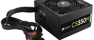
So, they gave us a 350-watt Power Man power supply for repair.
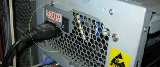
What do we do first? External and internal inspection. Let's look at the "offal". Are there any burnt radio elements? Maybe the board is charred somewhere, or a capacitor has exploded, or it smells like burnt silicon? We take all this into account during the inspection. Be sure to look at the fuse. If it burns out, then replace it with a temporary jumper for about the same amount of Amperes, and then measure the input resistance through two network wires. This can be done on the power supply plug with the “ON” button turned on. It should NOT be too small, otherwise, when you turn on the power supply, a short circuit will occur again.
Malicious pulsations
It also happens: the output voltages are normal, but the computer still does not work as it should - it freezes, reboots, does not see the device, distorts the sound, etc. One of the possible reasons for this behavior is parasitic ripples of the output voltages.
As a result of all the transformations of the input AC voltage (rectification, smoothing, re-conversion to an AC voltage with a higher frequency, reduction, another rectification and smoothing), the output should have a constant level, that is, its voltage should not change over time. When viewed with an oscilloscope, it should look like a straight line: the straighter the better.
In reality, a perfectly flat straight line at the output of a power supply unit is something out of science fiction. A normal indicator is the absence of amplitude fluctuations of more than 50 mV along the 5 V and 3.3 V lines, as well as 120 mV along the 12 V line. If they are larger, as, for example, in this oscillogram, the problems described above arise.
The causes of noise and ripple are usually a simplified circuit or poor-quality elements of the output smoothing filter, which is usually found in cheap power supplies. And also in old ones that have exhausted their resources.
Unfortunately, it is extremely difficult to identify a defect without an oscilloscope. And this device, unlike a multimeter, is quite expensive and is not needed on the household very often, so you are unlikely to decide to buy it. The presence of pulsations can be indirectly judged by the swinging of the needle or the running of numbers on the multimeter display when measuring DC voltages, but this will only be noticeable if the device is sensitive enough.
We measure voltages
If everything is OK, we turn on our power supply to the network using the network cable that comes with the power supply, and do not forget about the power button if you had it off.
Next, measure the voltage on the purple wire
My patient showed 0 volts on the purple wire. I take a multimeter and connect the purple wire to ground. Ground is black wires with the inscription COM. COM – short for “common”, which means “general”. There are also some types of “lands”:
As soon as I touched the ground and the purple wire, my multimeter made a meticulous “ppiiiiiiiiiiiiiiiiiiiiiiiiiiiiiiight” sound and showed zeros on the display. Short circuit, definitely.
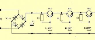
Well, let's look for a circuit for this power supply. After googling the Internet, I found a diagram. But I found it only on Power Man 300 Watt. They will still be similar. The only differences in the circuit were the serial numbers of the radio components on the board. If you know how to analyze a printed circuit board for compliance with the circuit, then this will not be a big problem.
And here is the circuit for Power Man 300W. Click on it to enlarge to full size.
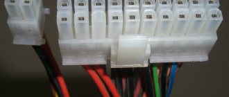
Marking for power supply wires
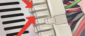
Where the pins marked GND (Ground) are ground, and pins 8, 13 and 16 are control signals. Thus, by closing pins 16 and 15 (or any black GND), you can turn on the power supply without connecting the motherboard. 2 wires are connected to pin 13 at once, one of which is a tap. The wires have a smaller cross-section, unlike standard wires, which is 22 according to American wire gauge. While the cross-section of the wires on pin 13 is only 18. For standard power supplies, the above motherboard connector pinout table is universal and suitable for all ATX motherboards.
Marking for power supply wires.
We are looking for the culprit
As we see in the diagram, standby power, hereinafter referred to as standby power, is designated as +5VSB:
Directly from it goes a zener diode with a nominal value of 6.3 Volts to the ground. And as you remember, a zener diode is the same diode, but it is connected in reverse in circuits. The zener diode uses the reverse branch of the current-voltage characteristic. If the zener diode were live, then our +5VSB wire would not short to ground. Most likely the zener diode has burned out and the PN junction is destroyed.
What happens when various radio components burn from a physical point of view? Firstly, their resistance changes. For resistors, it becomes infinite, or in other words, goes into a break. With capacitors it sometimes becomes very small, or in other words, goes into a short circuit. With semiconductors, both of these options are possible, both a short circuit and an open circuit.
In our case, we can check this in only one way, by unsoldering one or both legs of the zener diode, as the most likely culprit of the short circuit. Next, we will check whether the short circuit between the duty switch and ground has disappeared or not. Why is this happening?
Let's remember some simple tips:
1) When connected in series, the rule of greater than greater works, in other words, the total resistance of the circuit is greater than the resistance of the larger resistor.
2) With a parallel connection, the opposite rule works, less than the smaller, in other words, the final resistance will be less than the resistance of the resistor of the smaller value.
You can take arbitrary resistor resistance values, calculate them yourself and see for yourself. Let's try to think logically, if one of the resistances of parallel-connected radio components is zero, what readings will we see on the multimeter screen? That's right, also equal to zero...
And until we eliminate this short circuit by desoldering one of the legs of the part that we consider to be problematic, we will not be able to determine in which part we have a short circuit. The point is that during audio testing, ALL parts connected in parallel to the part that is in a short circuit will ring short with the common wire!
We try to remove the zener diode. As soon as I touched it, it fell apart in two. No comments…
What's the output?
Efficiency does not always mean serviceability.
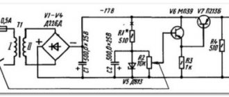
The power supply may well turn on, but not produce the required voltages, not output the Power_Good signal to the board (or output too early), sag (reduce output voltages) under load, etc. To check this, you will need a special device - a voltmeter (or better yet, a multimeter ) with DC voltage measurement function. For example, like this:
Or any other. There are a lot of modifications of this device. They are freely sold in radio and electrical stores. For our purposes, the simplest and cheapest one is quite suitable.
Using a multimeter, we will measure the voltage at the connectors of a working power supply and compare the values with the nominal values.
Normally, the output voltage values at any load (not exceeding the permissible for your power supply) should not deviate by more than 5%.
Measurement order
- Turn on the computer. The system unit must be assembled in the usual configuration, i.e. it must contain all the equipment that you use constantly. Let's let the power supply warm up a little - we'll just work on the PC for about 20-30 minutes. This will increase the reliability of the indicators.
- Next, launch the game or test application to fully load the system. This will allow you to check whether the feeder is able to supply energy to the devices when they are operating at maximum consumption. the Power Supply stress test from the program as a load .
- Turn on the multimeter. We set the switch to 20 V DC voltage (the DC voltage scale is indicated by the letter V, next to which a straight and dotted line is drawn).
- We connect the red probe of the multimeter to any connector opposite the colored lead (red, yellow, orange). Black is the opposite of black. Or we fix it on any metal part on the board that is not under voltage (voltage should be measured relative to zero).
- We take readings from the device display. 12 V is supplied through the yellow wire, which means the display should show a value equal to 12 V ± 5%. In red – 5 V, the normal reading will be 5 V ± 5%. According to orange, respectively – 3.3 V± 5%.
Lower voltages on one or more lines indicate that the power supply is not pulling the load. This happens when its actual power does not meet the needs of the system due to wear of components or poor workmanship. Or maybe because it was initially selected incorrectly or stopped coping with its task after a computer upgrade.
To correctly determine the required power of a power supply, it is convenient to use special calculator services. For example, . Here the user should select from the lists all the equipment installed on the PC and click “ Calculate ”. The program will not only calculate the required feeder power, but also offer 2-3 suitable models.
It's not the zener diode
We check whether the short circuit in the duty and ground circuits has been eliminated or not. Indeed, the short circuit has disappeared. I went to the radio store to get a new zener diode and soldered it. I turn on the power supply, and... I see how my new, just purchased zener diode emits magical smoke)...
And then I immediately remembered one of the main rules of a repairman:
If something burns out, first find the reason for it, and only then replace the part with a new one or risk getting another burnt out part.
Cursing to myself, I bite the burnt zener diode with side cutters and turn on the power supply again.
That’s right, the duty is too high: 8.5 Volts. The main question is spinning in my head: “Is the PWM controller still alive, or have I already burned it out?” I download the datasheet for the microcircuit and see the maximum supply voltage for the PWM controller, equal to 16 Volts. Phew, looks like it should pass...
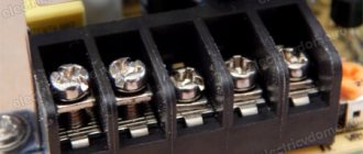
Molex connectors
This type of 4 pin PATA connectors (Molex 8981) is the most common and universal. If the required connector is missing, using a Molex 8981 connector and a special adapter (for example, 4 pin —> 6 pin) you can supply power to the video card, or using another adapter (for example, 4 pin —> 3 pin) you can connect an additional fan.
The versatility of the connector is explained by the presence of the most “demanded” voltages on the contacts, the pinout of which looks like this:
- Yellow – +12V;
- Black – GND;
- Black – GND;
- Red – +5V.
Using the Molex 8981 connector, several different devices, adapters, adapters and splitters can be connected to the power supply, the number of which is limited by the power of the power supply and the cooling system inside the case. The splitters allow you to get two or three (tee) connectors from one Molex 8981 connector at once. Adapters are designed to replace the missing connector on the power supply by connecting to the Molex 8981 connector.
It will be interesting➡ How to check the magnetron for serviceability with a multimeter
SATA connectors
Most modern storage devices, including hard drives and optical drives, use the SATA interface for both power supply and information transfer. Power via SATA is supplied through a 15-pin connector, to which 5 wires are connected, which is why the connector is called a 5-pin connector. But this definition is incorrect.
The connector pinout looks like this:
- Orange – +3.3V;
- Orange – +3.3V;
- Orange – +3.3V;
- Black – GND;
- Black – GND;
- Black – GND;
- Red – +5V;
- Red – +5V;
- Red – +5V;
- Black – GND;
- Gray – signal;
- Black – GND;
- Yellow – +12V;
- Yellow – +12V;
- Yellow – +12V;
This pinout is correct for the supplied SATA power connectors, since there is a gray signal wire and an orange one with a voltage of + 3.3V. The presence of these wires is required for correct operation in RAID arrays and for hot-swapping hard drives.
Different types of connectors.
Modern storage media powered by a SATA connector can also operate on four wires, like 4 pin PATA connectors. The devices have built-in voltage converters that help you use a PATA (Molex 8981) -> SATA power adapter to work with the drive, in the absence of a pre-installed SATA connector.
Computer power supply pinout
Connectors for video cards
Standard and higher-level power supplies use 6 and 8 pin connectors, or both may be present at once, for additional power supply to video cards. Modern video cards are designed to be installed in the PCI-E slot of the motherboard. Budget and entry-level video cards do not require additional power, but receive it from the PCI-E bus up to a maximum power consumption of 75 watts.
Gaming and professional video cards, possibly several cards connected using CrossFireX or SLI technology, depending on the “filling”, require increased power and power supply.
If the video card has average power consumption requirements, then an additional 6 or 8 pin connector is installed on it. The 6-pin connector adds 75 watts of power, and the 8-pin connector adds 150 watts. On very powerful video cards, two connectors can be used at once, and the total power consumed will be 300 watts. The pinout for these connectors looks like this:
- 8 pins: 1-2-3 – yellow +12V, 4-5-6-7-8 4 – black GND.
- 6 pins: 1-2-3 – yellow 12V, 4-5-6 – black GND.
Such components require increased power from the power supply, and it should also be taken into account that when operating in CrossFireX or SLI modes, increased heat dissipation will occur, and accordingly additional cooling power will be required. Depending on the model of the power supply, the lines for supplying +12V voltage may be separate, as written on the power supply casing or in its technical data sheet. 8 pin connectors are intended not only for powering video cards, but also for additional power supply to the processor.
Video card connectors.
It is worth noting that the connectors themselves are very similar in appearance and at first glance seem the same. In fact, the connectors have different pinouts and form factors; you should not try to insert the processor power connector into the video card connector or vice versa. If the video card requires additional power, but for some reason it is not connected or not supplied, then the card itself and the computer as a whole may fail to start.
Pinout
PSUs, regardless of power, are equipped with connectors for connecting to the chipset, HDD/SSD disk devices, video adapter, Molex, etc. I propose to consider each connection type separately so as not to get confused.
Motherboard
The main connector used here is 20-pin, the color designation of wires of which is generally accepted throughout the world. And if you look at the documentation for the chipset, you can find a letter designation there that makes it easier to understand the situation. Please note that the abbreviation GND (Ground) is “ground”, grounding. And the eighth, thirteenth and sixteenth pins are responsible for sending control signals. If you close contacts No. 16 and No. 15, the power supply will start even without connecting to the computer.
Motherboard connectors.
Computer Power Supply - Molex Wiring Diagram
It is a 4-pin connector, which is used to provide power to the graphics adapter, coolers and other devices. Two of the four wires supply 12/5 Volt DC power, and the pinout diagram looks like this:
It will be interesting➡ How to check a diode with a multimeter?
Power for drives
Modern hard and solid-state drives, as well as optical drives, are connected to the power supply via a 15-pin connector, to which five wires of different colors are connected. In some devices, a different SATA connection scheme is possible - “4+1”, where instead of five wires there are four + one separate one for power.
Interesting on the topic: How to check a zener diode.
Color pinout for video cards
Budget video adapter models can be powered by the chipset, but if you have powerful equipment with additional cooling and a large amount of memory, you will need to connect wires directly from the power supply. Nowadays both 8-pin and 6-pin connectors are actively used:
CPU power
If your computer is highly equipped, then its needs correspond. In some cases, it is necessary to provide additional make-up for the process handler and the cooling system.
PC processor connection.
The most commonly used connectors are:
- 8-pin – all black wires are GND, and all yellow wires are 12 Volts;
- 4-pin – similar to the previous scheme.
But for coolers, so-called 3- or 4-pin FAN connectors are used:
- 4-pin: black – “ground”, green – signal for the tachometer, yellow – current 12 Volts, blue – PWM (PWM) – ability to control the rotation speed of the cooling fan;
- 4-pin: an alternative pinout is distinguished by the presence of a red wire - 12 Volts, and instead of green, a yellow wire is used - tachometer;
- 3-pin: GND grounding – black, power – red wire, yellow cable – tachometer. There is no cooler control.
So we figured out the issue of “pinout of wires in a computer power supply.” If you have questions about more modern models, leave messages under the article in the comment section.
How a modern computer power supply works - the pinout of wires is of interest to many users who want to understand the principle of operation of one of the most important hardware components of a desktop PC. Modular power supplies are becoming increasingly popular, where it is possible to disconnect unused elements, which will allow you to remove unnecessary cables. But in this publication I will talk about the wiring diagram of a conventional power supply installed in the vast majority of computers.
PC processor connection.
Pinout
PSUs, regardless of power, are equipped with connectors for connecting to the chipset, HDD/SSD disk devices, video adapter, Molex, etc. I propose to consider each connection type separately so as not to get confused.
Motherboard
The main connector used here is 20-pin, the color designation of wires of which is generally accepted throughout the world. And if you look at the documentation for the chipset, you can find a letter designation there that makes it easier to understand the situation.
Please note that the abbreviation GND (Ground) is “ground”, grounding. And the eighth, thirteenth and sixteenth pins are responsible for sending control signals. If you close contacts No. 16 and No. 15, the power supply will start even without connecting to the computer.
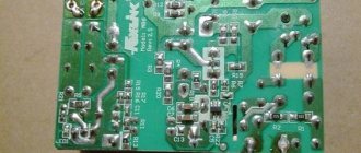
Checking the capacitors
I start googling about my problem on special sites dedicated to repairing ATX power supplies. And of course, the problem of overestimated standby voltage turns out to be a banal increase in the ESR of electrolytic capacitors in the standby circuits. We look for these capacitors in the diagram and check them.
I remember my assembled ESR meter
It's time to check what he is capable of.
I check the first capacitor in the duty circuit.
ESR is within normal limits.
Finding the culprit of the problem
I'm checking the second one
I wait for a value to appear on the multimeter screen, but nothing has changed.
I understand that the culprit, or at least one of the culprits of the problem, has been found. I resolder the capacitor to exactly the same one, in terms of nominal value and operating voltage, taken from the donor power supply board. I want to go into more detail here:
If you decide to put an electrolytic capacitor into an ATX power supply not from a donor, but a new one from a store, be sure to buy LOW ESR capacitors and not regular ones. Conventional capacitors do not work well in high-frequency circuits, but in the power supply, these are precisely the circuits.
So, I turn on the power supply and measure the voltage at the control room again. Having learned from bitter experience, I am no longer in a hurry to install a new protective zener diode and measure the voltage at the control room, relative to the ground. The voltage is 12 volts and a high-frequency whistle is heard.
Again I sit down to google about the problem of overvoltage in the duty room, and on the rom.by website, dedicated to both the repair of ATX power supplies and motherboards, as well as all computer hardware in general. I find my fault by searching for typical faults of this power supply. It is recommended to replace the capacitor with a capacity of 10 µF.
I measure ESR on the capacitor.... Ass.
The result is the same as in the first case: the device goes off scale. Some say, why collect some devices, such as swollen non-working capacitors, you can see that they are swollen, or have opened like a rose
Yes, I agree with this. But this only applies to large capacitors. Capacitors of relatively small values do not swell. There are no notches in their upper part through which they could open. Therefore, it is simply impossible to determine their performance visually. All that remains is to replace them with ones that are known to work.
So, after going through my boards, I found the second capacitor I needed on one of the donor boards. Just in case, its ESR was measured. It turned out to be normal. After soldering the second capacitor into the board, I turn on the power supply using the key switch and measure the standby voltage. Exactly what was required, 5.02 volts... Hurray!
I measure all other voltages at the power supply connector. Everything corresponds to the norm. Operating voltage deviations are less than 5%. It remains to solder a 6.3 Volt zener diode. I thought for a long time why the zener diode is 6.3 Volts when the voltage on duty is +5 Volts? It would be more logical to set it to 5.5 volts or similar if it was used to stabilize the voltage on the duty room. Most likely, this zener diode is placed here as a protective one, so that if the voltage on the control panel increases above 6.3 Volts, it will burn out and short-circuit the control panel circuit, thereby turning off the power supply and saving our motherboard from burning out when entering over-voltage through the control room.
The second function of this zener diode is, apparently, to protect the PWM controller from receiving too much voltage. Since the control room is connected to the power supply of the microcircuit through a fairly low-resistance resistor, almost the same voltage is supplied to pin 20 of the PWM microcircuit that is present in our control room.
Modern power supplies
There are certification standards for the energy efficiency and efficiency of a standard power supply, to measure the efficiency of power delivery and distribution of power to the computer's internal devices. It is the consumption of additional power that causes the appearance of new connectors, the presence of additional wires and contacts.
Interesting on the topic: How to check a zener diode.
Modern power supplies still contain the basic connectors used in earlier models, supplying devices with the standard voltage of 12, 5 and 3.3 volts. So, to connect to the motherboard, a 24 pin connector is used (from the English pin - pin, contact), which has undergone some changes. In older models of motherboards, and accordingly in power supplies, a 20 pin connector was used. Therefore, in most modern PSUs (power supply units), the connector is made in the form of a collapsible model, which is a standard 20 pin connector + an additional 4 pin connector for modern motherboard models.
It will be interesting➡ USB pinout: types of connectors and cable color assignments
When using only 20 pin, the additional 4 pin connector is removed (slides down along the plastic rails) and remains separately in reserve. Further, the power supply necessarily contains molex type connectors (after the name of the company that developed Molex) in 4 pin, for “powering” optical drives and other types of drives with the PATA (Parallel ATA) interface, replaced by the more modern SATA (Serial ATA) interface. To power SATA drives, there are usually two special 15 pin connectors (or PATA HDD –> SATA HDD power adapters).
And also in a modern power supply there should be power connectors for the central processor 4 or 8 pin (can be collapsible), a connector for powering the video card (6/8 pin, can also be collapsible and contain 6 pin + 2 separate contacts). Some models may have a Floppy connector (4-pin) to power floppy drives, some card readers and other devices that use this outdated connector.
How the power supply works.
Characteristics.
When choosing a power supply, you need to pay attention to the following characteristics:
- Power, measured in watts. It should be enough for all computer components. High-performance PCs (for example, gaming ones) consume a lot of energy due to the processor and video card. For such computers, it is worth buying units from 600W (or better yet, 1000). The consumption of each element must be taken into account. If there is insufficient power, the computer may not turn on or turn off spontaneously. An average office computer needs a 450-500W unit.
- Connectors for connection. Different blocks may be equipped with different connectors - this is important to consider in the case when, for example, a video card requires a separate connection and needs a 6-pin. If it is not available, you will have to buy an adapter separately. The connectors can be the following: 24+4(+4) pin - power supply to the motherboard.
- 6+2 pin - video card power supply
- Peripheral - rarely used in modern computers. Previously used to power IDE hard drives. Now it can be used to connect adapters.
- SATA - power supply for hard drives.
Related material: How to connect a capacitor