Voltage and color marking of cables
In order to bring to a single standard and minimize errors during installation and connection, it is customary to use wires with the appropriate insulation color for each voltage. This helps you quickly navigate when diagnosing your computer. The voltage wires are marked by color:
- 0 V (ground, common wire) – black;
- +5 volts – red;
- -5 volts – white;
- +12 volts – yellow;
- +3.3 volts – orange;
- -12 volts – blue.
Voltages not used to power computer components (control signals, etc.) use different colors, even if the voltage levels are the same as shown. Even little-known electronics manufacturers from Southeast Asia adhere to these standards. Another thing is that their color marking often makes it impossible to distinguish orange from yellow or red, and sometimes black from blue or purple.
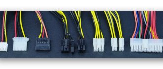
Types of connectors for powering PC components
The shape and position of the connectors of the internal power supply of personal computers is regulated by the ATX standard, which replaced the outdated AT. To connect devices to a source of electrical energy, the following are mainly used:
- ATX 20 (20+4, 24) – for power supply to the motherboard;
- 4 or 8 pin connector – for powering the processor;
- Molex – for powering many peripheral devices;
- SATA power – for powering hard or solid-state drives;
- PCI Expess – for powering video cards.
You can also find other connectors inside the PC. Some are obsolete and rare (for example, to power floppy drives), others are just gaining popularity.
For motherboard (ATX 20, 24 pin)
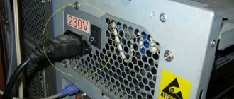
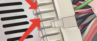
The largest connector coming from the power supply is connected to the motherboard. It contains 24 sockets (there are 24 pins on the board, respectively). You can also find power connectors for older computers with 20 pins. The pinout and color marking of the 24-pin connector is shown in the figure.
Pin assignment of the ATX 24 connector.
Some channels are signal and are used to control the power supply:
- pin 8 - Power OK (PWR_OK, PWR_good) - signal to the motherboard “power is on”;
- pin 16 -Power ON – signal from the motherboard, permission to supply voltage, in standby mode it is +5 volts (pulled up by a resistor), in enable mode – 0 volts (on the motherboard it is connected to the common wire);
- pin 13 additional brown wire - Sense - feedback for automatic voltage regulation.
You should also separately note the Stand by voltage on the purple wire (pin 9). It is designed to power the internal power supply circuit and at the same time serves as a standby voltage to start the computer.
The 20-pin connector lacks a section of the 4 outer pins - pairs 11-12 and 23-24. In the new 24-pin connector, this section can be made removable.
Motherboard connector 20+4.
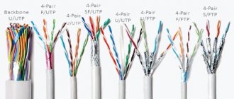
UTP straight-through and crossover cables
For two devices to transmit over a cable that directly connects them, the transmit terminal of one device must be connected to the receive terminal of the other device.
The cable must be crimped so that the transmit pin, Tx, taking a signal from device A at one end, is connected by wire to the receive pin, Rx, on device B. Likewise, the Tx pin of device B must be connected to the Rx pin of device A. If The Tx pin on the device is number 1 and the Rx pin is number 2, the cable connects pin 1 on one end to pin 2 on the other end. These "crossover" pin connections give this type of cable its name, a crossover cable.
To achieve this type of connection with a UTP cable, one end must be crimped according to the EIA/TIA T568A pinout and the other end must be crimped according to the T568B pinout.
To summarize, crossover cables directly connect the following devices on a LAN:
- Switch to switch
- Switch with hub
- Hub with hub
- Router to router (Ethernet port connection)
- Computer with computer
- Computer to router Ethernet port
In the illustration, identify the type of cable being used based on the devices being connected.
As a reminder, below is once again listed when to use which cable:
Use a straight cable to connect:
- Switch with router
- Computer with switch
- Computer with hub
Use a crossover cable to connect:
- Switch to switch
- Switch with hub
- Hub with hub
- Router with router
- Computer with computer
- Computer with router
MDI/MDIX selection
Many devices allow the UTP Ethernet port to be set to MDI or MDIX. This can be done in one of three ways, depending on the functionality of the device:
1. On some devices, the ports may have a mechanism that electrically changes the transmit and receive pairs. The port can be changed from MDI to MDIX using this mechanism.
2. During configuration, some devices allow you to choose whether the port should function as MDI or MDIX.
3. Many newer devices have an automatic crossover function. This feature allows the device to detect the required cable type and configures the interfaces accordingly. On some devices, this automatic detection is performed by default. Other devices require an interface configuration command to enable automatic MDIX discovery.
Using IOS CLI Help
- Creating LAN connections
- Easy to Install. Electromagnetic and Radio Interference
- Cable length. Price. Bandwidth
- Media Types
- LAN and WAN connection
- Speed and Types of Ports or Interfaces. Router Selection Factors
- Device Selection Factors
For CPU
Processor performance has been steadily increasing in recent decades. Their energy consumption is also growing. The processors are powered by voltage converters (VRMs) installed on the motherboard. About two decades ago, there was a massive transition in VRM power supply from +5 volts to +12 volts. This is due to the fact that less current is required to transmit the same power at a higher voltage. VRMs receive power via a separate cable with a 4-pin connector. Two contacts are for +12 volts (yellow wire) and two are for ground (black insulated wire).
Connector for VRM 4 pins.
The sockets on the connector and the pins on the board are arranged in two rows according to their intended purpose. Two pins serve as a key - their shape is different from the others, so an erroneous connection is impossible.
Pinout of 4-pin connector for VRM.
As productivity increased, the number of VRMs began to grow (first on servers, then on personal computers), so the question arose about rational power distribution. The issue was resolved by using 8-pin connectors. In them, the supplied power is distributed over 4 pairs of conductors.
Connector for VRM 8 pins.
Otherwise, there are no fundamental differences from the previous version. The connector contains two rows of sockets - +12 volts and 0 volts, only 4 in a row.
Pinout of 8-pin connector for VRM.
Progress cannot be stopped; energy consumption by processors will only increase. It looks like 4-pin connectors have outlived their usefulness and are becoming a thing of the past.
For video card (PCI Express)
Video cards of previous generations, which have low performance, and modern budget-class models are powered by the PCIe x 16 connector to which they are connected. The voltage to this terminal comes from the motherboard, which, in turn, is powered from the power supply through a 24(20)-pin connector. This is enough to transmit 75 watts.
PCI Express additional power connector.
This is not enough for modern high-performance cards, so they are provided with an additional PCI Express power input. Initially, it was a 6-pin connector and allowed for additional power supply of 75 watts. Very soon this bandwidth was not enough, and subsequent ATX standards were supplemented by an 8-pin connector and 120 watts.
Pinout of 6-pin and 8-pin connector.
This connector is also available in a universal 6+2 format, allowing it to be used for both 6-pin and 8-pin video card connectors.
Universal connector 6+2.
For the most modern video cards, manufacturers use connectors with twelve pins , but they are not yet widely used.
For hard drives and other devices (SATA, MOLEX)
To connect hard drives and some other peripherals, the Molex connector (named after the manufacturer) has been used for a long time. Its advantage is that it has plugs and sockets with large, powerful contacts that operate reliably at high currents.
The plug-in elements are arranged in one row. The connector also has a key to prevent incorrect connections. The two inner pins are for ground wires (black). Conductors with a voltage of +5 volts and +12 volts are connected to the extreme ones. Each contact is designed for a current of 11 amperes, which allows you to transmit 55 watts through a five-volt channel, and 132 watts through a twelve-volt channel. The pinout of the Molex connector is shown in the figure.
Molex connector pinout.
The power transmitted along the power line is limited not only by the load capacity of the connector, but also by the cross-section of the wires of the connected cable, the width of the printed circuit board tracks, etc. To determine the highest power of the line, it is necessary to select the capabilities of the least powerful component.
Due to the increased popularity of the SATA standard, Molex connectors are being replaced by SATA power connectors, which have 15 outputs. 3 pins are used for each voltage, which allows you to transmit more power without increasing the cross-section of the conductors and maintaining the flexibility of the cable. The voltage groups are separated by groups of neutral wires (3 conductors each). The connector pinout is in the table.
| Contact number | Wire color | Voltage level, V |
| 1 | Orange | +3,3 |
| 2 | Orange | +3,3 |
| 3 | Orange | +3,3 |
| 4 | Black | 0 V |
| 5 | Black | 0 V |
| 6 | Black | 0 V |
| 7 | Red | +5 |
| 8 | Red | +5 |
| 9 | Red | +5 |
| 10 | Black | 0 V |
| 11 | Black | 0 V |
| 12 | Black | 0 V |
| 13 | Yellow | +12 |
| 14 | Yellow | +12 |
| 15 | Yellow | +12 |
The SATA standard involves connecting devices with two connectors - for power and for data transfer. They should not be confused.
SATA power connector.
Video, audio, USB cables: characteristics, types, types
- VGA - VGA. The vast majority of VGA - VGA accessories are cables (see “Type”), they are used to connect monitors, TVs and projectors to signal sources with VGA connectors. However, there are also adapters of this format - usually these are the so-called. gender changer, allowing you to turn the connector female (“mother”) into male (“father”) or vice versa. VGA is an outdated but still fairly common interface for analog video transmission (without audio). Provides resolution up to 1280x1024 inclusive, which is enough for HD 720p, but is no longer enough for more advanced standards. - VGA - DVI. VGA - DVI cables and adapters are designed for analog signals and are made compatible with analog varieties of DVI - DVI-I and DVI-A. Note that adapters of this format usually have a DVI plug and a VGA socket, that is, they are designed for connecting VGA devices to DVI ports.
- VGA - HDMI. Most often we are talking about an adapter that connects to the HDMI output and outputs an analog video signal through a VGA socket (in some models, this socket can be supplemented with an audio connector). Such devices can be useful for connecting outdated TVs and monitors, as well as some specific types of video equipment (for example, projectors) to modern HDMI video devices.
...— DVI – DVI. Note that most accessories of this format are cables (see “Type”). There are very few adapters produced; they mainly play the role of adapters from smaller miniDVI connectors to the full-size version. DVI - video interface can provide both analog and digital signal transmission. Note that the DVI standard actually covers five types of connectors - analog DVI-A (almost out of use), digital DVI-D (in two versions - single link and dual link) and combined DVI-I (also in two versions). So when purchasing a DVI-DVI accessory, it doesn’t hurt to check exactly what connectors it uses and whether they will be suitable for your devices.
- 3RCA - 3RCA. Modification of the “RCA - RCA” cable, providing 3 plugs on each side and, accordingly, 3 separate wires for signal transmission. The main purpose of such cables is to transmit a signal via a composite or component interface: both provide 3 separate data transmission channels using RCA connectors, and using a triple cable for such a connection is more convenient than connecting three separate wires.
- SCART - SCART. SCART is a distinctive, large rectangular connector; This is the largest connector used in consumer electronics. At the same time, the SCART standard describes only the physical device of the connector and does not have “its own” signal format. SCART - SCART cables can transmit different types of signals - composite video/audio, component video, S-Video, commands for controlling video equipment from a common remote control, etc. However, audio and video signals are transmitted via SCART only in analog format, Because of this, this connector is sometimes considered obsolete. However, due to its convenience and versatility, it still continues to be quite widely used.
What adapters may be needed
When upgrading a computer or during initial assembly, it may turn out that the power supply does not have the necessary connectors for connecting peripheral devices, and it is not possible to select a power supply with all the necessary connectors. In this case, adapters from one type of connecting terminal to another will help out. So, if instead of an outdated hard drive with power via a Molex connector, a new device made according to the SATA standard is installed, you will need a harness with two connectors: Molex on one side, SATA-Power on the other.
Molex to SATA adapter.
If the power supply has unused SATA connectors, they can be used to power high-performance video cards. To do this you will need an appropriate adapter.
Adapter from 2xSATA to 8-pin.
If the motherboard has a connector for powering the VRM (processor) with 8 pins, and the power supply has a connector designed for 4 (and vice versa), you can also purchase a special adapter harness. But you don’t have to buy it - these connectors are fully compatible and fit perfectly together without adapter cables.
If the connector for the motherboard on the power supply contains 20 pins, and on the power supply - 24 (and vice versa), then a harness with two connectors will also help here.
Adapter for motherboard 20-24.
These are the main adapter cables. During the computer assembly process, you may need other adapters. All of them are available for sale.