Modern power supplies
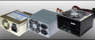
Today's power supplies are somewhat different from their predecessors, not only with modern designs, increased power and improved performance, but also with new connectors for devices that were not previously found in most conventional computers. This is due to the development of new devices or modification of old ones, increasing the technical characteristics of existing ones and, as a consequence, the need for additional power.
In addition to conventional power supplies, there are modular or partially modular units. The difference between the blocks is that in modular ones, in whole or in part, the cables are replaced with appropriate connectors for connecting them and fully comply with the connector standards of conventional blocks. This is good because unused wires will not be in the computer case and interfere with its modernization, as well as with the air circulation inside.
There are certification standards for the energy efficiency and efficiency of a standard power supply, to measure the efficiency of power delivery and distribution of power to the computer's internal devices. It is the consumption of additional power that causes the appearance of new connectors, the presence of additional wires and contacts.
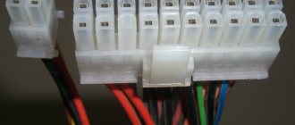
Modern power supplies still contain the basic connectors used in earlier models, supplying devices with the standard voltage of 12, 5 and 3.3 volts. So, to connect to the motherboard, a 24 pin connector is used (from the English pin - pin, contact), which has undergone some changes. In older models of motherboards, and accordingly in power supplies, a 20 pin connector was used. Therefore, in most modern PSUs (power supply units), the connector is made in the form of a collapsible model, which is a standard 20 pin connector + an additional 4 pin connector for modern motherboard models.
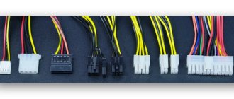
When using only 20 pin, the additional 4 pin connector is removed (slides down along the plastic rails) and remains separately in reserve. Further, the power supply necessarily contains molex type connectors (after the name of the company that developed Molex) in 4 pin, for “powering” optical drives and other types of drives with the PATA (Parallel ATA) interface, replaced by the more modern SATA (Serial ATA) interface. To power SATA drives, there are usually two special 15 pin connectors (or PATA HDD –> SATA HDD power adapters).
And also in a modern power supply there should be power connectors for the central processor 4 or 8 pin (can be collapsible), a connector for powering the video card (6/8 pin, can also be collapsible and contain 6 pin + 2 separate contacts). Some models may have a Floppy connector (4-pin) to power floppy drives, some card readers and other devices that use this outdated connector.
Computer power supply pinout - how it works
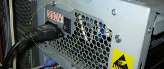
The power supply for a desktop computer is designed to convert alternating voltage 220v into reduced direct voltage with a nominal value of ±12v, ±5v, +3.3v. Power supply ±12v is used to operate connected computer components, usually the cooling system and drives. All microcircuits installed on the motherboard receive power via ±5v, +3.3v buses.
The pinout of the computer power supply from early years of production is not fundamentally different from modern power supplies. Of course, the current generation of power supplies are equipped with connectors for modern components.
Peculiarities
It's no secret that modern power supplies (PSUs) have become more powerful, have improved characteristics and, of course, a modern design than their predecessors 10-15 years ago. Also, many of you know (or are learning now) that modern power supplies have new connectors for components not previously used in personal computers (PCs). The presence of new connectors is associated with the emergence of new (or modernization of old) computer components, improvements in their performance characteristics and, as a result, the need for additional power.
A modern power supply meets energy efficiency and efficiency certification standards that are used to distribute power and efficiently deliver power to computer components. Due to the “greater gluttony” in power supply of the same video cards and motherboards, the power supply contains additional wires, contacts and connectors.
PSU connectors
The power supply contains the main connectors (electrical connectors) previously used in old power supplies, supplying voltages of 3.3, 5 and 12 Volts. Each connector pin is one Pin.
The motherboard is connected to the power supply via a 24 Pin male connector (the so-called bus), which has undergone changes with the improvement of motherboards. Previous generations of motherboards were connected to the power supply via a 20 Pin bus.
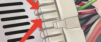
Because of this, in order to support any type of connection to the motherboard, the connector is made in the form of a collapsible design with a 20 Pin main and 4 Pin additional power connector.
If the motherboard only needs 20 Pin, the 4 Pin connector is removed (pull down along the plastic rails) and bent to make it easy to install a 20-pin bus.
To power optical drives and other drives with a PATA (Parallel ATA) connection interface, molex 8981 connectors (named after the manufacturer's company) are used.
Now they have been replaced by the modern SATA (Serial ATA) connection interface for drives of all types.
The central processor requires power from a 4 or 8 Pin connector (can be detachable).
The video card needs 6 or 8 Pin power. The connector can be dismountable to 6+2 Pin
Some modern power supplies may contain an outdated 4 Pin connector for floppy drives, card readers, etc.
Also, 3 and 4 Pin connectors are used to connect coolers.
Molex connectors
This type of 4 pin PATA connectors (Molex 8981) is the most common and universal. If the required connector is missing, using a Molex 8981 connector and a special adapter (for example, 4 pin —> 6 pin) you can supply power to the video card, or using another adapter (for example, 4 pin —> 3 pin) you can connect an additional fan.
The versatility of the connector is explained by the presence of the most “demanded” voltages on the contacts, the pinout of which looks like this:
- Yellow – +12V;
- Black – GND;
- Black – GND;
- Red – +5V.
Using the Molex 8981 connector, several different devices, adapters, adapters and splitters can be connected to the power supply, the number of which is limited by the power of the power supply and the cooling system inside the case. The splitters allow you to get two or three (tee) connectors from one Molex 8981 connector at once. Adapters are designed to replace the missing connector on the power supply by connecting to the Molex 8981 connector.
It will be interesting➡ Connection diagram for a pass-through two-key switch
SATA connectors
Most modern storage devices, including hard drives and optical drives, use the SATA interface for both power supply and information transfer. Power via SATA is supplied through a 15-pin connector, to which 5 wires are connected, which is why the connector is called a 5-pin connector. But this definition is incorrect.
The connector pinout looks like this:
- Orange – +3.3V;
- Orange – +3.3V;
- Orange – +3.3V;
- Black – GND;
- Black – GND;
- Black – GND;
- Red – +5V;
- Red – +5V;
- Red – +5V;
- Black – GND;
- Gray – signal;
- Black – GND;
- Yellow – +12V;
- Yellow – +12V;
- Yellow – +12V;
This pinout is correct for the supplied SATA power connectors, since there is a gray signal wire and an orange one with a voltage of + 3.3V. The presence of these wires is required for correct operation in RAID arrays and for hot-swapping hard drives.
Different types of connectors.
Modern storage media powered by a SATA connector can also operate on four wires, like 4 pin PATA connectors. The devices have built-in voltage converters that help you use a PATA (Molex 8981) -> SATA power adapter to work with the drive, in the absence of a pre-installed SATA connector.
Computer power supply pinout
Connectors for video cards
Standard and higher-level power supplies use 6 and 8 pin connectors, or both may be present at once, for additional power supply to video cards. Modern video cards are designed to be installed in the PCI-E slot of the motherboard. Budget and entry-level video cards do not require additional power, but receive it from the PCI-E bus up to a maximum power consumption of 75 watts.
Gaming and professional video cards, possibly several cards connected using CrossFireX or SLI technology, depending on the “filling”, require increased power and power supply.
If the video card has average power consumption requirements, then an additional 6 or 8 pin connector is installed on it. The 6-pin connector adds 75 watts of power, and the 8-pin connector adds 150 watts. On very powerful video cards, two connectors can be used at once, and the total power consumed will be 300 watts. The pinout for these connectors looks like this:
- 8 pins: 1-2-3 – yellow +12V, 4-5-6-7-8 4 – black GND.
- 6 pins: 1-2-3 – yellow 12V, 4-5-6 – black GND.
Such components require increased power from the power supply, and it should also be taken into account that when operating in CrossFireX or SLI modes, increased heat dissipation will occur, and accordingly additional cooling power will be required. Depending on the model of the power supply, the lines for supplying +12V voltage may be separate, as written on the power supply casing or in its technical data sheet. 8 pin connectors are intended not only for powering video cards, but also for additional power supply to the processor.
Video card connectors.
It is worth noting that the connectors themselves are very similar in appearance and at first glance seem the same. In fact, the connectors have different pinouts and form factors; you should not try to insert the processor power connector into the video card connector or vice versa. If the video card requires additional power, but for some reason it is not connected or not supplied, then the card itself and the computer as a whole may fail to start.
Pinout
PSUs, regardless of power, are equipped with connectors for connecting to the chipset, HDD/SSD disk devices, video adapter, Molex, etc. I propose to consider each connection type separately so as not to get confused.
Motherboard
The main connector used here is 20-pin, the color designation of wires of which is generally accepted throughout the world. And if you look at the documentation for the chipset, you can find a letter designation there that makes it easier to understand the situation. Please note that the abbreviation GND (Ground) is “ground”, grounding. And the eighth, thirteenth and sixteenth pins are responsible for sending control signals. If you close contacts No. 16 and No. 15, the power supply will start even without connecting to the computer.
Motherboard connectors.
Computer Power Supply - Molex Wiring Diagram
It is a 4-pin connector, which is used to provide power to the graphics adapter, coolers and other devices. Two of the four wires supply 12/5 Volt DC power, and the pinout diagram looks like this:
It will be interesting➡ How to check the zener diode for performance
Power for drives
Modern hard and solid-state drives, as well as optical drives, are connected to the power supply via a 15-pin connector, to which five wires of different colors are connected. In some devices, a different SATA connection scheme is possible - “4+1”, where instead of five wires there are four + one separate one for power.
Interesting on the topic: How to check a zener diode.
Color pinout for video cards
Budget video adapter models can be powered by the chipset, but if you have powerful equipment with additional cooling and a large amount of memory, you will need to connect wires directly from the power supply. Nowadays both 8-pin and 6-pin connectors are actively used:
CPU power
If your computer is highly equipped, then its needs correspond. In some cases, it is necessary to provide additional make-up for the process handler and the cooling system.
PC processor connection.
The most commonly used connectors are:
- 8-pin – all black wires are GND, and all yellow wires are 12 Volts;
- 4-pin – similar to the previous scheme.
But for coolers, so-called 3- or 4-pin FAN connectors are used:
- 4-pin: black – “ground”, green – signal for the tachometer, yellow – current 12 Volts, blue – PWM (PWM) – ability to control the rotation speed of the cooling fan;
- 4-pin: an alternative pinout is distinguished by the presence of a red wire - 12 Volts, and instead of green, a yellow wire is used - tachometer;
- 3-pin: GND grounding – black, power – red wire, yellow cable – tachometer. There is no cooler control.
So we figured out the issue of “pinout of wires in a computer power supply.” If you have questions about more modern models, leave messages under the article in the comment section.
How a modern computer power supply works - the pinout of wires is of interest to many users who want to understand the principle of operation of one of the most important hardware components of a desktop PC. Modular power supplies are becoming increasingly popular, where it is possible to disconnect unused elements, which will allow you to remove unnecessary cables. But in this publication I will talk about the wiring diagram of a conventional power supply installed in the vast majority of computers.
PC processor connection.
Pinout
PSUs, regardless of power, are equipped with connectors for connecting to the chipset, HDD/SSD disk devices, video adapter, Molex, etc. I propose to consider each connection type separately so as not to get confused.
Motherboard
The main connector used here is 20-pin, the color designation of wires of which is generally accepted throughout the world. And if you look at the documentation for the chipset, you can find a letter designation there that makes it easier to understand the situation.
Please note that the abbreviation GND (Ground) is “ground”, grounding. And the eighth, thirteenth and sixteenth pins are responsible for sending control signals. If you close contacts No. 16 and No. 15, the power supply will start even without connecting to the computer.
Pinout of the main power cable connector
The pinout of a computer's power supply starts with the largest and most important power cable - this is the cable connected to the motherboard. On old-style motherboards, the ATX connector is designed for 20 pins, while new generation motherboards already contain 24 pins in their connector. It is for this reason that new generation power supplies have cables with a 20+4 pin plug.
When pinouting a computer's power supply, it is important to know that the ATX plug is only suitable for powering the motherboard. This can be checked by looking closely at the contacts in the plug and connector - each of them is unique and suitable for only one purpose.
Computer power supply pinout under load
To check the functionality of the power supply, you can connect it without affecting the system as a whole. This is done so that in the event of a defective power supply, all components of the computer are not damaged. To start the power supply for the first time, you need to close contacts 6 and 7. If everything is done correctly, the power supply should signal an operation in the form of a spinning fan.
Note: Pin counts do not include the additional four pins for the ATX connector.
Power pinout for SATA
To update the IDE interface, a new SATA cable was introduced, which contained 15 pins. A total of five wires are connected to the plug, each of which occupies three contacts. The first three orange contacts operate with a voltage of 3.3 volts. The second three are COM contacts, that is, “ground”. The middle pins have an input voltage of 5 volts. The fourth triple is identical to the second. The last three contacts are already with a voltage of 12 volts.
Older versions of this cable had four wires of three pins, but with the interface update, support for 3.3 volt input voltage was added, which is indicated by the orange wire.
15-pin SATA power connector pinout
A pinout is an interface map that describes the pins that connect an electrical device or connector.
Below is a diagram of the layout of a standard 15-pin SATA power connector for version 2.2 of the ATX specification. If you use this pin chart to test power supply voltages, keep in mind that these voltages must be within ATX tolerances.
15-Pin SATA Connector Reference
| Pin | Name | Wire color | Description |
| 1 | +3.3VDC | Orange | +3.3 VDC |
| 2 | +3.3VDC | Orange | +3.3 VDC |
| 3 | +3.3VDC | Orange | +3.3 VDC |
| 4 | COM | Black | Earth |
| 5 | COM | Black | Earth |
| 6 | COM | Black | Earth |
| 7 | +5VDC | Red | +5 VDC |
| 8 | +5VDC | Red | +5 VDC |
| 9 | +5VDC | Red | +5 VDC |
| 10 | COM | Black | Earth |
| 11 | COM | Black | Land (Additional or other use) |
| 12 | COM | Black | Earth |
| 13 | +12VDC | Yellow | +12 VDC |
| 14 | +12VDC | Yellow | +12 VDC |
| 15 | +12VDC | Yellow | +12 VDC |
There are two less common SATA power connectors: a 6-pin connector called the slim connector (+5 VDC power supply) and a 9-pin connector called the micro connector (+3.3 VDC and +5 VDC power supply). current). The pinout tables for these connectors are different from those shown here.
PCI-E
It is this connector that is designed to power video cards; power supply manufacturers often make them red (and some blue) in color; there are 6-pin and 8-pin. In modern power supplies, the 8-pin can be composite, just like the connectors described earlier.
The PCI-E connector is the most popular in mining. Its purpose is to provide additional power to devices (video cards, in our case) connected to the PCI-Express bus of the motherboard. According to the specifications, the 6-pin provides 75 watts of additional power, and the 8-pin provides 150 watts. At the same time, the video card receives another 75 watts from the motherboard (or from the riser).
The video card may have several connectors for additional power. For example, you can take the NVIDIA GeForce GTX 980 Ti video card; its maximum power consumption, according to the manufacturers, is 250 Watts. Of this, the device receives 75 Watts from the motherboard, and connectors for at least 175 Watts are required. One 6-pin is not enough (up to 75 Watt), one 8-pin or two 6-pin (up to 150 Watt) is also not enough. Requires one 6-pin and one 8-pin (total 225 watts). Look at the picture below - that’s right, everything is correct.
Additional power connectors for video cards
At the beginning of the 2000s, the power consumption of video cards increased sharply, which required special power connectors for them, adopted in the ATX12V 2.x specifications.
The PCI Express x16 Graphics 150W-ATX Specification 1.0 was adopted by the PCI-SIG working group in 2004. She introduced a 6-pin connector that can provide 75 W of power to the video card. And another 75 W are taken from the PCI-E x16 slot. The resulting total of 150 watts is sufficient to power mid-level video cards, for example, GeForce GTX 1650 SUPER .
But these power options quickly became insufficient and soon the PCI Express 2.0 specification was adopted, which already provided an 8-pin power connector for video cards. The 8-pin power connector made it possible to transmit 150 W of power and, together with 75 W coming from the PCI-E x16 slot, the result was 225 W, which was already enough for high-performance video cards.
Video card manufacturers usually try to unload power on the PCI-E x16 slot and provide power reserves for overclocking, so video cards with a consumption of 120 watts and higher, for example, GeForce GTX 1660 SUPER , are increasingly equipped with an eight-pin power connector.
The design of the connectors allows the connection of a 6-pin power cable to an 8-pin connector. But, most likely, you will need a special adapter, because in this case the video card will recognize by the signal contacts which cable is connected to the power connector.
The 8-pin connector is usually made collapsible, which allows it to be connected to a 6-pin socket.
It is impossible to insert connectors of this type incorrectly: the bevels on the pins are located in a strictly defined order. But you need to connect the power all the way - until the safety tab snaps into place.
Molex
Initially, this connector was designed to power hard drives and floppy drives, but currently for modern devices this function is performed by SATA connectors (about them below), and Molex connectors are used to power various additional equipment.
The advantage of Molex is the presence of 5 and 12 Volt lines at the same time, and a current of up to 11 Amps can flow through each line, that is, the power of a 12-Volt line is 132 Watts, and a 5-Volt line is 55 Watts. You can often find information on the Internet that Molex provides 187 watts of power. This is true, but the additional power connector for video cards has only 12 Volt lines, and the 5 Volt line is not used. In mining rigs, Molex connectors are used to connect risers, cooling fans, additional power to the motherboard, and as a replacement for missing PCI-E connectors.
Many adapters have been invented using Molex. And some of them pose a real fire hazard!
The top most fire-hazardous adapters are headed by the MOLEX->8-pin PCI-E adapter. The power consumption of the video card via the 8-pin connector, as I noted above, is up to 150 Watts. Molex is rated at 132 watts.
Molex->6-pin PCI-E and 2xMolex->8-pin PCI-E adapters should be used with caution. There is no excess in power here, but you shouldn’t relax. Adapter manufacturers often use low-quality materials - thin wires, cheap plastic, unreliable metal parts. This may also cause a fire. After installing such connectors, regularly monitor their condition.
The safest option is 2xMOLEX->6-pin PCI-E adapters. A good power reserve allows you to avoid fire due to overheating, but there is still a danger of problems arising due to poor contact, as a result of which this adapter will actually turn into a 1xMolex->6-pin PCI-E, and this is the first step to big problems.
It is advisable to avoid using Molex adapters to connect video cards. However, it is relatively safe to use Molex connectors to power risers (let me remind you, their consumption is no more than 75 Watt), including using adapters.
Molex pinout
- Conclusion
- Color
- Purpose
| 1 | Yellow | +12 volts |
| 2 | Black | Ground One black wire serves as ground for +5 volt power, the second for +12 volt power. |
| 3 | Black | Earth |
| 4 | Red | +5 volts |
Molex connectors
Molex PC peripheral power connector is an electrical connector designed and manufactured by . The connectors have been actively promoted by the manufacturer since the 50s of the last century and found a place in the first computers.
Connectors of this type meet the accepted standard for constructing electrical circuits: the plug has an outer shell, the socket is inserted inside the connector. For the first time, the Molex connector was used to supply power to a floppy drive manufactured by Shugart.
The number of contacts can be from 2 to 24. There are also 3 contact diameters: 1.57 mm transmits current up to 5 A, 2.36 mm no more than 8.5 A, 2.13 to 8 A. The connector body usually has a flat shape and made of nylon.
ATX P4
A 4-pin processor power connector and a 6-pin additional power connector for PCIe
ATX P4 graphics cards were introduced by Intel for the Pentium 4 processor. It connects to the motherboard and powers the processor.
Today, most motherboards have between 4 and 8 pins. The new power supply standards use an 8-pin connector (sometimes called 12V EPS) made up of 2 x 4-pin blocks, ensuring compatibility with older motherboards and the classic ATX P4.
Molex connector
Let's start with the most ancient connector, which has reached our times almost unchanged, having appeared on the first “personal devices”. This is the well-known 4-pin connector called Molex.
Today, the scope of application of this connector has narrowed to powering case fans, front panels of PC cases, splitters and power adapters for video cards and drives. For example, video card power adapters “Molex - PCI-E 6 pin”. Despite the fact that the connector produces up to 11 A per contact, which means it can give the video card, in theory, 132 watts of power, it should be used with extreme caution.
It must be taken into account that the thickness of the wires may not correspond to such power, and the contacts themselves may be loose, with a loose fit. As a result, this is fraught with heating of wires, contacts and melting of insulation.
If you absolutely need such an adapter, choose a model with two Molex connectors.
ATX 20, 20+4, 24
Main 24-pin power connector and 20+4 pin power connector
If the video cards do not have enough power received through the PCI-Express connector, then use an additional 6-pin cable from the power supply. The additional power connector for PCI-Express video cards is similar to the additional power connector for the processor.
ATX 20 pin pinout
Conclusion- Name
- Description
- Color
| 1 | +3.3v | +3.3v | Orange |
| 2 | +3.3v | +3.3v | Orange |
| 3 | GND | (Housing, Common wire) | Black |
| 4 | +5v | +5v | Red |
| 5 | GND | (Housing, Common wire) | Black |
| 6 | +5v | +5v | Red |
| 7 | GND | (Housing, Common wire) | Black |
| 8 | PowerGood | Power supply ready signal | Grey |
| 9 | +5v Standby | +5v, Make-up in Standby mode | Lilac (Purple) |
| 10 | +12v | +12v | Yellow |
| 11 | +3.3v | +3.3v | Orange |
| 12 | -12v | -12v | Blue |
| 13 | GND | (Housing, Common wire) | Black |
| 14 | Power ON | Starting the power supply. | Green |
| 15 | GND | (Housing, Common wire) | Black |
| 16 | GND | (Housing, Common wire) | Black |
| 17 | GND | (Housing, Common wire) | Black |
| 18 | -5v | -5v | White |
| 19 | +5v | +5v | Red |
| 20 | +5v | +5v | Red |
style=”width: 100%; color: black; height: 1px; background-color:gray;”>
FLOPPY
The FLOPPY connector, used to power a floppy disk drive (FMD), is also obsolete, but unlike Molex, it is practically not used. Therefore, as a rule, new power supplies do not have it. Nevertheless, we present its pinout.
| FLOPPY connector pin assignments | ||
| Contact | Signal | Wire color |
| 1 | +5 V | red |
| 2 | general | black |
| 3 | general | black |
| 4 | +12 V | yellow |
Since float drives are still used on outdated computer models, as noted above, there are MOLEX/FLOPPY adapters that can be purchased in addition, or even found in the box with a new power supply.
So we figured out what connectors are equipped with ATX power supplies, and we also know the pinout of each of them. Now we can independently select a suitable power supply, and, if necessary, we can find the voltages that interest us on its connectors.
Power connector for 3.5″ drives
Another connector that is almost never found on new power supplies. Previously used to power 3.5″ drives and some expansion cards.
About the cross-section of wires coming out of the computer power supply
Although the currents that the power supply can supply to the load amount to tens of amperes, the cross-section of the output conductors, as a rule, is only 0.5 mm2, which allows current transmission through one conductor of up to 3 A. You can find out more about the load capacity of the wires from the article “On choosing a wire cross-section for electrical wiring.” However, all wires of the same color are soldered to one point on the printed circuit board, and if a block or module in a computer consumes more than 3 A of current, voltage is supplied through the connector along several wires connected in parallel. For example, voltage +3.3 V and +5 V is supplied to the motherboard via four wires. This ensures that up to 12 A of current is supplied to the motherboard.
- Color marking of PSU ATX
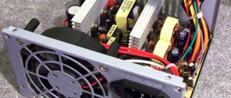
- ATX power supply repair
- BP ATX load block
24-pin motherboard power connector
This connector appeared in the ATX12V 2.0 specifications in 2004 and replaced the legacy 20-pin connector. It can provide quite serious power to power the processor, video card and motherboard: 145.2 W via the +3.3 V line, 275 W via the +5 V line and 264 W via the +12 V line (using Molex Plus HCS contacts).
Note. Molex contacts are certified for 6 A. Molex HCS - up to 9 A. And Molex Plus HCS - up to 11 A.
Installing an additional video card connector in the computer's power supply
Sometimes there are seemingly hopeless situations. For example, you bought a modern video card and decided to install it in your computer. There is the necessary slot on the motherboard for installing a video card, but there is no suitable connector on the wires for additional power supply to the video card coming from the power supply. You can buy an adapter, replace the entire power supply, or you can independently install an additional connector on the power supply to power the video card. This is a simple task, the main thing is to have a suitable connector, it can be taken from a faulty power supply.
First you need to prepare the wires coming from the connectors for the offset connection, as shown in the photo. An additional connector for powering the video card can be connected to the wires going, for example, from the power supply to drive A. You can also connect to any other wires of the desired color, but in such a way that there is enough length to connect the video card, and preferably nothing to them was no longer connected. The black wires (common) of the additional connector for powering the video card are connected to the black wire, and the yellow wires (+12 V), respectively, to the yellow wire.
The wires coming from the additional connector for powering the video card are tightly wrapped with at least three turns around the wire to which they are connected. If possible, it is better to solder the connections with a soldering iron. But even without soldering, in this case the contact will be quite reliable.
The work of installing an additional connector for powering the video card is completed by isolating the connection point, several turns, and you can connect the video card to the power supply. Due to the fact that the twisting points are located at a distance from each other, there is no need to isolate each twist separately. It is enough to cover only the area where the wires are exposed with insulation.
Connecting the cooler to power
The fan can be connected to connectors on the motherboard, video adapter, or to the power supply itself. The main difficulty in solving this problem is the so-called pinout, i.e., recognizing the contacts of an electrical circuit. Currently, coolers with three and four connection pins are widespread.
Connection procedure
The cooler is powered by simply connecting the contacts and, as a rule, does not cause any difficulties. To cool the central processor and video adapter, separate outputs are provided on the boards.
In some cases, however, it may be necessary to connect directly to the power supply:
For fans with four working contacts, the wires are colored as in Option 1, but blue is added, which is used for software speed control. Contacts with a voltage of +7 V with the standard connection method are connected to the tachometer leg on the motherboard; if directly powered from the power supply, they are not needed, like the blue contact.