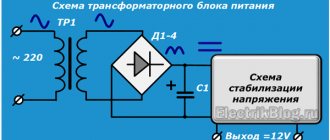
Any measuring system available in a modern laboratory or at a radio amateur's workplace must include an inexpensive and reliable power supply unit (PSU). In order to improve its performance characteristics, experts advise using automatic switching of transformer windings in the power supply. This significantly reduces parasitic power dissipation in the output stages and facilitates the operation of any laboratory current source.
This approach is especially in demand in cases where, under operating conditions, a power supply with a voltage regulation range of 50 Volts, for example, and with a load current of at least 5 Amps is in demand. Industrial sources with such declared characteristics are not available to the average user due to their high cost. This is precisely what forces him to use the principle and circuit of automatic switching of the transformer windings in the power supply.
What is the transformer winding switching system used for?
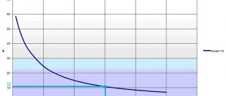
When independently manufacturing a power supply with such characteristics, the contractor has to solve a number of problems, the most important of which is ensuring the required transfer characteristics over the entire spectrum of output voltages. Let's consider an example when there is a power source designed for a maximum voltage of up to 50 Volts.
If in a certain situation it was necessary to set the exact value of the output voltage to only 5 Volts with a load current of 5 Amps, 225 Watts of power will be uselessly dissipated in the output circuits. This figure is obtained from the calculation 50-5 = 45 (Volts), which after multiplying by 5 Amperes gives the indicated amount of power lost without any effect.
Important! In this situation, the efficiency of such a source will be extremely low.
To eliminate this drawback, it is necessary to take special measures to significantly reduce losses in inductive output stages. To do this you will need to do the following:
- Somehow switch the secondary windings of the power transformer (TS), which will allow, if necessary, to take less power from it.
- Use a more economical pulse mode for converting electricity.
- Use a pre-made pre-regulator that works on the same pulse principle.
On the other hand, it is well known that a reliable and multifunctional laboratory power supply should not have pulse units that lead to nonlinear distortions. In this case, a purely linear transformation is considered more rational and effective.
Additional information: for not very complex amateur circuits, a regular switching power supply will do.
However, to set up more precise electronic equipment, you will need a standard device containing units with a linear transfer characteristic.
Electronic switch of transformer windings of laboratory power supplies.
Nikolay Petrushov
In the first part of our story, we examined the switch circuit of the secondary winding of a power transformer, made using electromagnetic relays. For those who do little work with the power supply in current stabilization mode and do not change the output voltage under load, the circuit is quite suitable and will last a very long time, but it also has certain disadvantages. When adjusting the output voltage of the power supply unit, clicks of the relays being activated are heard. Since switching of the windings occurs with interruption of the current, the relay contacts may burn, especially in current stabilization mode with a connected load. The electronic version of the switch for the secondary windings of the LBP transformer, discussed below, does not have all these disadvantages.
The electronic switch circuit is made using triacs and operates in volt addition mode. She absolutely does not care at what point in the half-cycle of the alternating voltage the triac turns on or off, and how many triacs turn on. It simply adds or decreases (but does not interrupt) the input voltage to the power supply, which depends on the number of enabled triacs and, accordingly, the output voltage of the power supply. Idea for using volt additive suggested by kotosob
- from the forum of the Soldering Iron site, I am here only offering my version of its implementation. The circuit of this version of the switch, just like in the first part, is assembled on the K555IV3 microcircuit. Without it, it would be difficult to implement the triac switching algorithm, and the number of taps of the secondary winding of the power transformer and the diodes and triacs used in the circuit would increase, with similar switching limits and voltages used. The power part of the switch uses four triacs (respectively four triac optocouplers) and three diode bridges, which, when using triacs in isolated cases, can be installed on a common radiator.
Diagram of the transformer winding switching unit.
As can be seen from the diagram, it is similar to the relay version of the switch discussed in the first part. To set switching thresholds, zener diodes for an operating voltage of 6.2 - 6.8 volts are also used here. It is better, of course, to use zener diodes with an operating voltage of 6.8 volts, then the switching thresholds will be as follows - 6.8 v; 13.6v; 20.4v; 27.2 v; 34 v; 40.8 v. The electronic switch uses four triacs that switch the secondary windings of the power transformer in such a way that the output voltage from the bridge supplied to the input of the power supply (to the electrolytic filter capacitors) varies from 8 to 44 volts, with a change limit of 6 volts, depending on the output voltage of the power supply, that is, equal to 8, 14, 20, 26, 32, 38, 44. The required voltage of the secondary windings of the power transformer for this version of the power supply is indicated on the diagram of the power part of the switch. With such a switch, you can build a power supply with an output voltage variable from 0 to 40-45 volts, with a load current of 5-10 amperes with good efficiency over the entire range of output voltages.
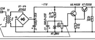
Power section diagram.
If you use electrolytic capacitors with an operating voltage of 80 volts in the power supply filter, you can build a power supply whose maximum output voltage can reach 55-65 volts. To do this, it will be necessary to wind a power transformer, the first three sections of which (I, II, III) have an output voltage of 8 volts, the next two (IV, V) 16 volts each, respectively, with a wire designed for the required load current. The voltages supplied to the input of the power supply in this case will be the following - 8, 16, 24, 32, 40, 48, 56 volts. Also, all zener diodes will need to be replaced with zener diodes with a stabilization voltage of 7.5 - 8.2 volts, to expand the switching thresholds of the electronic switch. The operation of the electronic circuit is similar to the relay switch circuit described in the first part, and the power part works as follows. If the output voltage of the power supply does not exceed 6.2-6.8 volts (the operating voltage of the zener diode), then all triacs are closed, and a voltage of 8 volts is supplied to the power supply input from the third part of the secondary winding of the power transformer. When the output voltage increases, the first zener diode opens, a logical zero appears at output 1 (pin 9) of the K555IV3 microcircuit, the LED of the optocoupler U3 lights up, and the triac VS3 opens. The second part of the secondary winding is connected to the diodes of the second bridge VD9-VD10 and 6 volts are added to the 8-volt winding. As a result, the output voltage increases by 6 volts (8+6). In this case, the rectifying diodes VD7-VD8 are blocked by the increased reverse voltage supplied to them from the diodes VD9-VD10 and are excluded from operation. Subsequently, when the output voltage of the power supply unit increases, the second zener diode opens. At output 2 (pin 7) of the K555IV3 microcircuit - a logical zero appears, at output 1 (pin 9) - a logical one. The LED of optocoupler U2 lights up, triac VS2 opens, and the LED of optocoupler U3 goes out and triac VS3 closes. Diodes VD3-VD4 (and VD7-VD8) come into operation, which block diodes VD5-VD6. 12 volts are added to the 8-volt winding, and 6 volts (VS3, VD9-VD10) are turned off. The final voltage at the power supply input increases by another 6 volts (8+12). Subsequently, when the output voltage of the power supply unit increases, triacs VS1-VS3 (more precisely, VS3-VS1) are triggered in binary code and the voltage increases in steps of 6 volts to the maximum. The last one to open is triac VS4. When the output voltage of the power supply decreases, everything happens in the reverse order. The winding switch is assembled on a printed circuit board measuring 56x77 mm.
Switch printed circuit board.
The printed circuit board for the switch was kindly provided by our website user Anatoly Sokolov ( anatolurew
). A printed circuit board in Sprint-Layout format from Anatoly Sokolov has been added to the article in the attachment (archive) for download. Foreign analogues for the K555IV3 microcircuit, as indicated in the first part - 74LS/HC/HCT 147. As diode bridges (VD1-VD4, VD5-VD8, VD9-VD12) and power triacs, you can use any triacs and diode bridges, as well as separate diodes designed for the required current and corresponding voltage. As transistors - any low-power transistors. You can also use any of the available optocouplers, but only triac ones. transistor and diode ones will not work. In extreme cases, you can replace them with low-power electromagnetic (reed) relays. In this case, 330 ohm resistors, which are connected in series with the optocoupler LEDs, are excluded, and the relay contacts are connected instead of the optocoupler triacs. Application:
Download the archive.
Principle of operation
To solve this problem, when developing industrial power supplies, engineers took the first path, which involves the presence of several switched taps in the secondary winding. To switch them, a variety of methods are used, including the following options:
- Manual switching (via flip switches, for example).
- Use of standard switching relays controlled by a separate electronic unit.
- Inclusion of high-speed semiconductor elements (triacs) into the output chain.
- Use of modern controllers as a control unit.
This switching allows you to use only the part of the secondary winding corresponding to the required output voltage value (in the example above, this is 5 Volts).
Thus, the principle of operation of such a circuit is to artificially regulate the output alternating voltage by setting its fixed value, less than the full value of the transformer output. This approach eliminates the unjustified consumption of energy spent on pointless heating of rectifier elements (in typical circuits, this function is performed by power transistors).
Note! To increase the efficiency of such a circuit and reduce the degree of heating of the transformer core, experts advise increasing the number of taps of the secondary winding to the maximum value.
After such modification of the output circuits, the contacts of the biscuit switch are connected to them, through which it will be possible to set the required power mode for the output. The only inconvenience of this method is the increase in the number of output voltage controls. The inefficiency of the mechanical method of connecting the output windings of the transformer forces us to look for new (more rational) solutions.
Current transformers
A current transformer is an electrical sensor designed to read alternating current and obtain a signal that is practically not phase-shifted relative to the measured current and has information about its magnitude.
Current transformers
The output signal of the current transformer should correspond almost linearly to the measured current.
The primary winding of the measuring current transformer is formed by one or, less commonly, several turns of wire and connected in series with the current that is to be measured. Often the role of the primary winding is played by a large cross-section bus, onto which a magnetic circuit with a secondary winding laid on it is placed. The magnetic core should be chosen so that it does not go into saturation. Typically, amorphous metals or nanocrystalline alloys are used as magnetic core materials.
The secondary multi-turn winding is made with a winding wire of small diameter. The transformation coefficient can reach several thousand. There can be several secondary windings. An example is the device TOL-10-I-7 (a reference measuring current transformer with three secondary windings). The voltage of the secondary winding can be high, which imposes requirements for the use of high-quality insulation with a high breakdown voltage and compliance with safety standards when servicing such a transformer by qualified personnel.
Reference measuring current transformer type TOL-10-I
A layer of insulation is often placed between the primary and secondary windings to provide galvanic isolation. In some cases, the galvanic isolation voltage can reach thousands of kilovolts.
A precision resistor is usually connected to the output of the current transformer and a voltage corresponding to the current through the primary winding is removed from this resistor. If a high-resistance resistor is used, or if a resistor is not connected at all, but the voltage is removed directly from the secondary winding, then the output signal will be proportional to dl / dt, and such a current transformer can be differentiating.
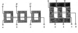
Current transformer connection diagrams
Using current transformers, the primary current is reduced to values that are most convenient for powering measuring instruments and relays. Typically, the secondary currents of current transformers do not exceed 1 or 5 A.
The primary windings of current transformers are included in the electrical circuit, and the secondary windings are connected to the load (devices, relays). Opening the secondary winding of a current transformer can lead to an emergency mode, in which the magnetic flux in the core and the emf at the open ends sharply increase. In this case, the maximum value of the EMF can reach several kilovolts. With magnetic saturation, active losses in the magnetic circuit increase, which leads to heating and burning of the winding insulation.
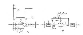
Current transformer connection diagrams. a – a star, b – a triangle, c – an incomplete star, d – the difference between the currents of two phases, e – the sum of the currents of three phases.
The secondary windings of current transformers that are not used in operation are short-circuited using special clamps.
The primary windings of current transformers are isolated from the secondary windings at full operating voltage. However, in case of insulation damage, measures are taken to ensure the safety of work in secondary circuits. To do this, one end of the secondary winding of the current transformers is grounded.
Why the secondary winding of a current transformer cannot be left open-circuited
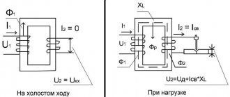
The current transformer operates normally in short circuit mode and does not allow idle operation. When working with current transformers, it is necessary to ensure that the secondary winding of the current transformer does not remain open when the primary winding is connected.
The secondary winding of a current transformer should not be left open-circuited while the primary winding is carrying the current being measured, for the following reasons.
When the secondary circuit opens, which can happen, for example, when the ammeter is turned off, the counter magnetic flux F2 disappears, therefore, a large alternating flux F1 begins to pass through the core, which causes the induction of a large EMF in the secondary winding of the current transformer (up to a thousand volts), since the secondary winding has a large number of turns. The presence of such a large EMF is undesirable because it is dangerous for operating personnel and can lead to breakdown of the insulation of the secondary winding of the current transformer.
Circuit diagram for connecting a measuring current transformer
When a large flux F1 occurs in the core, large eddy currents begin to be induced in the core itself, the core begins to heat up very much, and with prolonged heating, the insulation of both windings of the transformer may fail. Therefore, we must remember that if you need to turn off the measuring instruments, you must first short-circuit either the secondary or primary winding of the transformer.
Some current transformers have special devices for this purpose (sockets with plugs, jumpers, etc.). If there are no such devices, then you need to make them yourself.
Current transformers are classified according to the following criteria:
1. By purpose:
- measuring;
- protective;
- intermediate (for including measuring instruments in current circuits of relay protection, for equalizing currents in differential protection circuits, etc.);
- laboratory (high accuracy, as well as with many transformation ratios).
2. By type of installation:
- for outdoor installation (in open distribution devices);
- for indoor installation;
- built into electrical devices and machines: switches, transformers, generators, etc.;
- overhead - placed on top of the bushing (for example, on the high-voltage input of a power transformer);
- portable (for control measurements and laboratory tests).
3. According to the design of the primary winding:
- multi-turn (coil, with loop winding and with the so-called “figure-of-eight winding”);
- single-turn (rod);
- tire
4. According to installation method:
- checkpoints;
- supporting
5. To perform insulation:
- with dry insulation (porcelain, bakelite, cast epoxy insulation, etc.);
- with paper-oil insulation and with capacitor paper-oil insulation;
- gas-filled (SF6);
- with filling with compound.
6. According to the number of transformation steps:
- single stage;
- two-stage (cascade).
7. According to operating voltage:
- for rated voltage over 1000 V;
- for rated voltage up to 1000 V.
8. Special current transformers:
- zero sequence;
- Rogowski belt.
The advantages of current transformers include the simplicity of organizing galvanic isolation, insignificant heat generation and high repeatability of parameters from instance to instance. Current transformers are used in current meters and in systems for protecting power supplies from overloads and short circuits in loads.
Advantages
The principle of splitting the output voltage into small parts provides the following advantages:
- The ability to set a wide range of operating voltages at the device output at your discretion.
- Reduce losses in the output stages of the power supply.
- Increase overall efficiency and ultimately save on energy consumption.
All these advantages can be obtained only if mechanical control methods or electronic switching circuits are effective. The order in which each of them is constructed will be discussed in the next section.
Options for schematic solutions
When designing power supplies that ensure economical consumption of electricity and eliminate heat losses in the transformer core, the following options are possible:
- Installation of conventional turn switches in the output circuits.
- Application in the same chains of relay-type switches.
- Use of modern triac switches in output control lines.
- Application of a programmable electronic switch (controller) in a conversion circuit.
Next, each of these methods of controlling the output voltage will be discussed in more detail.
Simple switch block
This type of switch can be made in the form of a conventional biscuit switch, designed for a certain number of control knob positions. Each of them corresponds to a given number of turns of the secondary coil of the transformer, with an increase in the number of which its output voltage increases.
Important! The advantages of this method include ease of implementation, while the disadvantages include the inconvenience of constantly switching the knob, which has to be controlled manually.
In addition, switching in this case occurs very slowly and leads to parasitic transients in output circuits with high inductance.
Relay
The principle of this method of controlling the power supply output stages is based on the use of special switching elements called relays. With their help, it is possible to significantly increase the switching speed and eliminate the occurrence of large voltage (current) surges. The diagram of such a switch can be found in the figure on the right.
It shows that to control the position of the relay contacts, a separate coil is used, the voltage from which is rectified and supplied to a simple electronic module made on the basis of transistors.
Note! In this case, the executive part of the switching device is the relay contacts, which operate much faster than the human hand switching the biscuit device.
Therefore, transient processes in this circuit are noticeably smaller, and the risk of overvoltages in the output circuits is significantly reduced. On the other hand, relay contacts wear out over time, and strong sparking often leads to disruptions in the normal operation of the converter. Much more reliable are some types of semiconductor devices (triacs, for example), when switching them in circuits, parasitic interference is eliminated.
Triac
A triac circuit for controlling winding switching (more precisely, an example of it) is shown in the figure on the left. In this situation, switching of the turns of the output coil is carried out through electronic transitions of special semiconductor devices - triacs. To control their switching, the circuit provides an electronic module that is triggered by a signal received from the user.
In this case, optical pairs of the same triac type are used to decouple the control and switching circuits. The signal to their input elements comes from the outputs of transistors controlled by an electronic switch on operational amplifiers. The two-sided output voltage control circuit includes:
- Power supply on stabilizer VR1.
- Turn-on delay module made on transistors VT1-VT3.
- Display unit based on LED elements LED1-LED3.
- Typical LM393 dual comparator.
- Logic type 74HC86.
- Optocouplers MOC3083.
- Input divider R6-R7.
In the process of setting up this circuit, resistor R7 sets a fixed input voltage, divided by the divider R6-R7 by ten. Example: when a voltage of 20 Volts is supplied from the power supply, its value at the non-inverting inputs of the LM393 will be only 2 Volts. And resistors R8, R10 are used to set threshold switching voltages
How is the adjustment carried out?
The adjustment procedure involves the following operations:
- in the initial position the turns are closed, according to the location of the closing elements of the selector;
- the unit is disconnected from voltage;
- by turning the handle or turning on the mechanized drive, the closing element of the selector moves with a change in the working number of turns on the winding;
- the unit is connected to the network.
Also read: What is a surge suppressor (SPD)
Switching is done to the required value, according to the required characteristics of the consuming equipment.