Metal detectors are quite expensive devices that are designed to detect metals beneath the soil surface. But many enthusiasts prefer to assemble such devices at home.
The article contains a detailed description of how to assemble a “Pirate” metal detector with your own hands. The reader will be provided with 4 diagrams of this device, assembled using different elements.
Purpose
The Pirate metal detector is a simple metal detector capable of detecting small coins at depths of up to 0.5 meters. Larger objects are recorded at depths of up to 1.5 meters. This device is very convenient for beginners and more experienced treasure hunters. The device belongs to the pulse metal detectors. It works on the principle of interaction of the magnetic field (MF) from the coil with the magnetic field of the metal. Capable of detecting precious metals at a depth of up to 1 meter. Such detection is carried out by reacting to vortex flows from the surface of non-magnetizable metals. Metals that have their own magnetic field are detected due to the difference in the MF potentials from the generator and the object.
Many radio amateurs choose the Pirate metal detector because of its ease of assembly, fairly good penetrating ability and the ability to change parameters. Compared to more expensive types of these devices, a homemade Pirate can be assembled using cheap materials and parts, and still produce a device with great sensitivity. Next, diagrams of this device will be given on various components, with a detailed description of the operating principle.
Powerful DIY metal detector Pirat
Similar metal detectors can be purchased for about 100-300 dollars. The price of metal detectors is strongly related to their detection depth; not every metal detector can “see” coins at a depth of 15 cm. In addition, the cost of a metal detector is also greatly affected by the presence of a metal type recognizer and the type of interface; fashionable metal detectors are sometimes equipped with a display for convenient operation .
This article will look at an example of assembling a powerful metal detector called Pirat with your own hands. The device is capable of catching coins underground at a depth of 20 cm. As for large objects, it is quite possible to work at a depth of 150 cm.
Video of working with a metal detector: This metal detector received this name due to the fact that it is pulsed, this is the designation of its first two letters (PI-pulse). Well, RA-T is consonant with the word radioskot - this is the name of the developers’ site where the homemade product was posted. According to the author, the Pirate is assembled very simply and quickly; even basic skills in working with electronics are enough for this.
The disadvantage of such a device is that it does not have a discriminator, that is, it cannot recognize non-ferrous metals. So it will not be possible to work with it in areas contaminated with various types of metals.
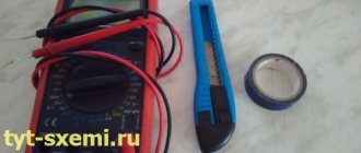
Materials and tools for assembly: - KR1006VI1 microcircuit (or its foreign analogue NE555) - the transmitting unit is built on it; — transistor IRF740; - K157UD2 microcircuit and BC547 transistor (the receiving unit is assembled on them); — wire PEV 0.5 (for winding the coil); — NPN type transistors; - materials for creating the body and so on; - electrical tape; - soldering iron, wires, other tools.
The remaining radio components can be seen in the diagram. You also need to find a suitable plastic box for mounting the electronic circuit. You will also need a plastic pipe to create a rod on which the coil is attached.
Metal detector assembly process:
Step one. Creating a printed circuit board
The most complex part of the device is, of course, the electronics, so it makes sense to start there. First of all, you need to make a printed circuit board. There are several board options, depending on the radio elements used. There is a board for NE555, and there is a board with transistors. All the necessary files to create the board are included in the article. You can also find other board options on the Internet.
Now the board needs to be soldered, all electronic elements are installed exactly as in the diagram. In the picture on the left you can see the capacitors. These capacitors are film capacitors and have high thermal stability. Thanks to this, the metal detector will work more stably. This is especially true if you use a metal detector in the fall, when it is sometimes quite cold outside.
Step three. Power supply for metal detector
To power the device, you need a source from 9 to 12 V. It is important to note that the device is quite voracious in terms of energy consumption, and this is logical, because it is also powerful. One Krona battery will not last long here; it is recommended to use 2-3 batteries at once, which are connected in parallel. You can also use one powerful battery (best rechargeable).
Step four.
Assembling a coil for a metal detector Due to the fact that this is a pulse metal detector, the accuracy of coil assembly is not so important here. The optimal diameter of the mandrel is 1900-200 mm; a total of 25 turns need to be wound. After the coil is wound, it needs to be thoroughly wrapped on top with electrical tape for insulation. To increase the detection depth of the coil, you need to wind it on a mandrel with a diameter of about 260-270 mm, and reduce the number of turns to 21-22. In this case, a wire with a diameter of 0.5 mm is used.
After the coil is wound, it must be installed on a rigid body; there should be no metal on it. Here you need to think a little and look for any suitable housing. It is needed to protect the coil from shock while working with the device.
The leads from the coil are soldered to a stranded wire with a diameter of about 0.5-0.75 mm. It is best if there are two wires twisted together. Step five. Setting up a metal detector
When assembling exactly according to the diagram, you do not need to adjust the metal detector; it already has maximum sensitivity. To fine-tune the metal detector, you need to twist the variable resistor R13, you need to achieve rare clicks in the speaker. If this can only be achieved in the extreme positions of the resistor, then it is necessary to change the value of resistor R12. The variable resistor should set the device to normal operation in the middle positions. [center]
If you have an oscilloscope, you can use it to measure the frequency at the gate of transistor T2. The pulse duration should be 130-150 µs, and the normal operating frequency is 120-150 Hz.
How to operate a metal detector
After turning on the device, you need to wait about 10-20 seconds for the operation of the metal detector to stabilize. Now you can twist resistor R13 to adjust. After this, you can start searching.
imp_tranz.rar [38.66 Kb] (downloads: 11738)
Source
Become the author of the site, publish your own articles, descriptions of homemade products and pay for the text. Read more here.
Scheme
You can assemble the Pirate metal detector using various microcircuits, as well as transistors. The choice of electronic component will determine the penetrating ability of the coil, the detection width, as well as the frequency and speed of signal reception. It will also be more convenient for a beginner to use transistors, since they are easy to find in old equipment. Further details about the types of device circuits.
NE555
When choosing a Pirate metal detector circuit based on the NE555 chip, it is worth considering that this component will act as a frequency amplifier for the device’s transmitter. The receiver for such a circuit can be assembled on the K157UD2 microcircuit.
This principle will help strengthen the signal from the transmitter, as well as greatly reduce interference when using a coil of a wider diameter.
TL072
The Pirate metal detector can be assembled using a TL072 chip. This component will form the basis of the device's receiver. You will need 2 such elements. In the circuit with this element, the NE555 microcircuit will be used as the basis for the transmitter. This selection does not affect the quality of penetration, but significantly stabilizes the operating frequency, evens out the signal tonality, and significantly reduces interference.
This is especially important when interacting with large and numerous magnetized objects located in damp soil at different depths.
Transistors
The circuit of the Girat metal detector using transistors is much simpler. It is chosen if it is difficult to find previously described microcircuits. In such a circuit, transistors act as the basis for a frequency generator and receiver. The main disadvantage of using these elements is the complexity of subsequent configuration. Transistors have a very narrow ability to increase the frequency parameters sent by the signal generator. Also, this parameter will be difficult to adjust to the receiving node of the future device. For fine tuning and adjustments you will need an oscilloscope. The main advantage of the chosen circuit is its greater resistance to overheating of variable resistors.
More expensive and complex microcircuits become unusable when high temperatures occur due to the presence of high resistance resistors in the device.
K561LA7
The latter circuit is based on the K561LA7 microcircuit. This element is divided into 4 sectors:
- 2 sectors are used as a frequency generator. It is this principle that allows you to obtain a high signal and maintain it when the diameter of the coil increases by 3–5 centimeters.
- Sector 3 is responsible for receiving the reflected signal from a metal object in the soil. The frequency of reactions to magnetized objects and precious metals also increases significantly. Discrimination is not high, but with some operating experience you can learn to identify metal by sound.
- Sector 4 is a signal filter. It compares the level of the sent and received pulse and transmits the final frequency tone to the amplifier. This sector is very important if there are objects in the ground that are no larger than the diameter of a coin.
This scheme is very well suited for subsequent settings. Having a built-in filter can significantly increase the ability to detect gold among magnetizable elements in the soil.
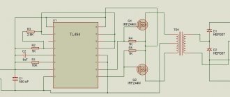
Scheme of a simple and quite effective metal detector “PIRAT”
Anyone can assemble such a device, even those who are completely far from electronics, you just need to solder all the parts as in the diagram. The metal detector consists of two microcircuits. They do not require any firmware or programming.
Power supply is 12 volts, you can use AA batteries, but it’s better to use a 12V battery (small)
The coil is wound on a 190mm mandrel and contains 25 turns of PEV 0.5 wire
Characteristics: - Current consumption 30-40 mA - Reacts to all metals, no discrimination - Sensitivity 25 mm coin - 20 cm - Large metal objects - 150 cm - All parts are inexpensive and easily accessible.
List of required parts: 1) Soldering iron 2) Textolite 3) Wires 4) Drill 1mm
Here is a list of required parts
Diagram of the metal detector itself
The circuit uses 2 microcircuits (NE555 and K157UD2). They are quite common. K157UD2 - can be picked out from old equipment, which I did with success
Be sure to take 100nF film capacitors, like these, take the voltage as low as possible
Print out the board sketch on plain paper
We cut a piece of textolite to its size.
We apply it tightly and press it with a sharp object in the places of future holes.
This is how it should turn out.
Next, take any drill or drilling machine and drill holes
After drilling, you need to draw tracks. You can do this through photoresist, LUT, or simply paint them with Nitro varnish with a simple brush. The tracks should look exactly the same as on the paper template. And we poison the board.
In the places marked in red, place jumpers:
Next, we simply solder all the components into place.
For K157UD2 it is better to install an adapter socket.
To wind the search coil you need a copper wire with a diameter of 0.5-0.7 mm
If there is none, you can use another one. I didn’t have enough varnished copper wire. I took an old network cable.
He took off the shell. There were enough wires there. Two cores were enough for me, and they were used to wind the coil.
According to the diagram, the coil has a diameter of 19 cm and contains 25 turns. I’ll immediately note that the coil needs to be made of such a diameter based on what you will be looking for. The larger the coil, the deeper the search, but a large coil does not see small details well. The small coil sees small details well, but the depth is not great. I immediately wound three coils of 23cm (25 turns), 15cm (17 turns) and 10cm (13-15 turns). If you need to dig up scrap metal, then use a large one; if you are looking for small things on the beach, then use a smaller reel, but you’ll figure it out for yourself.
We wind the coil on anything of a suitable diameter and wrap it tightly with electrical tape so that the turns are tightly next to each other.
The coil should be as level as possible. The speaker took the first one available.
Now we connect everything and test the circuit to see if it works.
After applying power, you need to wait 15-20 seconds until the circuit warms up. We place the coil away from any metal, it is best to hang it in the air. Then we begin to twist the 100K variable resistor until clicks appear. As soon as the clicks appear, turn it in the opposite direction; as soon as the clicks disappear, that’s enough. After this, we also adjust the 10K resistor.
Regarding the K157UD2 microcircuit. In addition to the one I picked out, I asked one more from a neighbor and bought two at the radio market. I inserted the purchased microcircuits, turned on the device, but it refused to work. I racked my brains for a long time until I simply installed another microcircuit (the one I removed). And everything started working right away. So this is why you need an adapter socket, so that you can select a live microcircuit and not have to worry about desoldering and soldering.
Purchased chips
Mine and the one I got from my neighbor
Everything is ready, all that remains is to make a rod and place the board in the case and go looking for treasures)
Here is the VIDEO of the tests
Tests at home were carried out on a medium reel with a diameter of 15 cm. So the gold ring caught in the air at 18 cm, scissors 30 cm. table lamp 50cm. which is not bad enough for such a metal detector.
Questions and suggestions to ( [email protected] ) or in the comments.
Download a sketch of the board diagram: imp-MS.rar [11.03 Kb] (downloads: 15870)
Become the author of the site, publish your own articles, descriptions of homemade products and pay for the text. Read more here.
Additional details
Having decided on the circuit that will be used in the Pirate metal detector, it is necessary to prepare additional radio components and start preparing the printed circuit board. Next, a general list will be presented for all previously provided schemes.
Resistors
These components are very common. They can be easily removed from outdated electronic and electrical devices. The parts list is as follows:
- Nominal 1 kOhm in quantity 1 pc.
- 1.6 kOhm - 1 pc.
- 47 kOhm - 1.
- 62 kOhm - 2.
- 100 kOhm - 1.
- 120 kOhm - 1.
- 470 kOhm - 1.
- 2 MOhm - 1.
- 100 Ohm - 1.
- 10 Ohm - 1.
- 470 Ohm - 1.
- 150 Ohm - 1.
- 220 Ohm, power 1 W - 1.
- 390 Ohm, power 0.5 W - 1.
You can also replace the presented list with modern analogues. During operation, it will be possible to replace some resistors. Their resistance often affects the operation of nearby components and causes them to overheat.
Capacitors
To operate the circuit, you will need electrolytic capacitors of the following ratings:
- 1 uF, 16 volts - 2 pcs.
- 10 uF, 16 volts - 2.
- 100 uF, 16 volts - 1.
A 1 nF ceramic capacitor and two 100 nF film elements are also required.
Microcircuits
Depending on the chosen scheme, the following components will be needed:
- NE555 or its domestic analog KR1006VI1.
- TL072 or analogue K157UD2.
- K561LA7.
When choosing a microcircuit, it is worth considering the different number of pins on these elements and methods of connection to the overall circuit.
Transistors
Those who decide to assemble a Pirate metal detector using transistors will need the following elements:
- IRF740.
- BC547.
- BC557
All these components can be easily replaced with complete domestic analogues.
Also, to assemble the circuit you need 2 1N4148 diodes, a speaker with a resistance of up to 8 Ohms, and an inductor up to 2 Ohms. The metal detector is powered by a battery or accumulator with a voltage of up to 12 volts.
After all the necessary radio components have been collected, you need to start creating a printed circuit board. A complete guide will follow.
Deep modernization of the “Pirate” metal detector.
We reduce current consumption, increase sensitivity, and increase the stability of the popular metal detector.I’m sitting quietly, not bothering anyone, and then bam - a letter with an eccentric content arrives in my mail: - Dear author! Could you tell me how to improve the performance of the Pirate metal detector? When powered by a 9-volt battery, the sensitivity is not enough, but the current consumption is acceptable; when you switch to a 12-volt battery, the circuit’s performance becomes better, but you’ll get tired of constantly recharging it. The diagram is attached... Forget me! - I said, looking around, just in case, I went to my website, climbed there, crossed myself... There is nothing like metal detectors there! - Why on earth should I understand anything in this area? - I am writing to the author of the question. — Of course, about 100 years ago in magazines, I saw simple circuits of beat-based metal detectors, but nothing more. - No, this one is not beating - it’s pulsed, the guys from Radioskot developed it. There's just something there: a transmitter and a receiver. You feel like two fingers on the asphalt, but I don’t have enough knowledge and no one can really answer! Well, somehow,” I thought, “two fingers on the asphalt, this is not the process that I had dreamed about for so long since kindergarten,” and I wanted to send the intrusive questioner off in a gentle but decisive manner, but..., wandering around network and having studied the question, I discovered that this topic excites the minds of a fair number of radio amateurs. It turns out to be a popular topic! Yes, there are many more gold nuggets buried in the great expanses of our country,” I outlined the possible origins of such interest and decided to puzzle myself with this question. The result of the theoretical study of the topic was a page - a link to the page. And now we smoothly move on to “Pirate”.
It so happened that the “radio cattle guys” didn’t have to push themselves that hard. The first implementation of such a metal detector was found in the bourgeois magazine “Everyday Electronics August 1989”, and a very similar circuit “PI Metal Detector” was published on September 30, 2008 by S.V. Smith. So the only thing left for the lads to do was to throw out what they thought were unnecessary radio components. How much is extra - we’ll leave it up to them, it works, well, thank God!
Let's look at the operating principle of this metal detector. After the transmitter emits a short pulse of magnetic induction, a damped current pulse appears in the desired metal object and is maintained for some time (due to the phenomenon of self-induction), causing a time-delayed reflected signal. This reflected signal carries useful information about the object, which must be registered by the receiving part of the metal detector.
Fig.1
Figure 1 (left) shows the transmitting part of the “Pirate”. The pulse generator generates short current pulses arriving at a frequency of 150 Hz into the emitting coil, where they are converted into magnetic induction pulses. Since the emitting coil has a pronounced inductive nature, voltage surges across it can reach hundreds of volts. And since this coil is also a receiving coil, it is necessary to take care of limiting this voltage at the input of the receiving part of the recorder. For this purpose, a diode limiter D1-D2 is used. The right side of the figure shows diagrams of the voltage on the limiter in the absence of a metal object in the coil’s coverage area (blue color) and the presence of a piece of iron (red color). As you can see, there is an effect of pulse expansion due to re-emission of the target. The larger the metal object, or the closer it is to the search coil, the more pronounced the expansion effect will be, i.e. By calculating the difference between the durations of the red and blue pulses, one can judge the size and depth of the object.
Moreover, the main part of the device’s current consumption is precisely the process of pumping the energy coil necessary for sufficient radiation power. How can this consumption be reduced? Stupidly - reduce the pulse repetition rate. Let's think about why the frequency of these pulses was chosen in “Pirate” to be 150 Hz? Yes, it’s very simple - this frequency must be recorded by a speaker. The speaker is small, it will hardly reproduce this frequency, and if you lower it too much, it will be completely silent like a fish, and if not silent, then click slightly. Okay, forgot about the speaker! To what extent can this frequency be reduced? To values that allow you to comfortably move the metal detector coil in space without losing the speed of target detection. It is clear to the hula hoop that lowering the frequency to 50Hz (or 50 spitting search impulses per second) will not have any negative effect on the speed of movement. But a threefold decrease in frequency will allow at least a threefold reduction in current consumption. Further reductions can be achieved by using digital signal processing via low-power CMOS chips.
Well, enough of this dull theory, it’s time to move on to the electrical circuit diagram!
Fig. 2 Scheme of a pulse metal detector
Figure 2 shows a diagram of the formation of a pulse, the duration of which is directly proportional to the power of the signal reflected from the metal object. The driver uses CMOS logic elements “2AND-NOT” with Schmitt triggers at the inputs. It is the presence of these triggers that allows microcircuits to avoid prolonged transient processes and ensures their own current consumption close to zero. The pulse frequency of the generator, as we have already agreed, is 50 Hz, the duration of the pump pulses is 150 μs (this value is optimal for the coil used in the metal detector). In the simplest version, the coil is wound on a 200 mm mandrel and contains about 30 turns of wire. Its shape and design can have different shapes; it is important that the resulting inductance is 300-330 μH. The beginning of the prohibition pulse coincides with the beginning of the transmitting pulse. The duration is regulated by variable resistor R2 and should be a value equal to the discharge time of the emitting coil. The DA1A operational amplifier amplifies the signal coming from the output of the diode limiter and makes its output shape closer to rectangular.
For a better understanding of the operation of the circuit, I will provide voltage diagrams at various points.
Fig. 3 Pulse metal detector voltage diagrams
I think no further explanation of the shaper’s operation is required.
As a matter of fact, now all we have to do is measure the duration of the output pulse and record it using any method convenient for the user. This can also be done conveniently using purely digital means.
Fig.4 Pulse duration meters
Figure 4 shows two options for a pulse duration meter: the first with LED indication, the second with duration registration using a changing audio frequency. Both devices are based on the CD4017 (K561IE8) chip, which is a decimal counter with a decoder. The decoder works in such a way that it provides a logical one at only one output at any time, which is extremely useful for reducing the power consumption of the circuit when operating on LED matrices. How does it all work?
When a positive differential of the measured signal (input pulse) arrives at the input of the device, a generator built on IC1.1 is started, the output pulses of which, with a frequency specified by the R1-C1 chain, are supplied to the clock input of the counter IC2. The counter begins to do its immediate job - counting. At the end of the measured signal, its level becomes zero, the generator stops and so does the counter, indicating the number of counted pulses as “one” at the corresponding output. The more the counter manages to count by this moment, the longer the duration of the signal arriving at the input. Elements IC1.2 and IC1.3 are designed to stop the counter at the moment the “one” appears on the last digit in order to prevent its subsequent restart. Variable resistor R1, which regulates the frequency of the generator, is also responsible for the sensitivity of the metal detector: the higher the frequency, the higher the sensitivity.
So, we sorted this out, throw out the LEDs, connect the generator to the meter (Fig. 4 on the right). The generator is made on IC3.1, IC3.2, T1 and is a device whose frequency is generated by the control current. The control current, in turn, depends on the values of resistors R4-R11 connected to the corresponding outputs of the meter. With the values indicated in the diagram, the minimum frequency corresponding to the shortest duration of the input pulse will be about 500 Hz, the maximum, corresponding to the longest duration: ≈ 1 kHz. The remaining resistors should be selected from a grid of intermediate values. In the process of increasing the frequency of the generator, there is a simultaneous increase in the volume in the sound emitter, associated with a decrease in the duty cycle of the output pulses (approaching their shape to a meander).
To maintain high stability of the metal detector, all logic elements must be powered with a stabilized voltage taken from the integrated stabilizer VR1 (Fig. 2). In fact, for the classic “Pirate” such a stabilizer would also be quite useful!
Pay
To make a board for mounting radio components, you need to download any of the provided diagrams. Next you will need:
- Cut a blank of the required size from plastic or textolite. All sizes of boards for the described circuits will be presented below.
- Transfer the image onto the blank.
- Using a permanent marker, trace all the paths in the drawing.
- Etch the workpiece. For 100 ml of hydrogen peroxide you need 30 grams of citric acid and 5 grams of salt. The workpiece is placed in the resulting composition for 30 minutes.
- Next, you need to clean the surface of the tracks on the board with sandpaper and degrease it with alcohol.
- After degreasing, use a thin drill to drill holes for the radio components.
- At the final stage, degrease the surface of the board again and completely tin the tracks with tin.
- After this operation, drill the holes again.
If there is no opportunity or experience to create a board in the described way, you can simply transfer the image to the surface of the plastic. Next, drill holes for the legs of the elements. Paths may not be used. Solder all elements using copper, single-core wire. This approach is more labor-intensive and can lead to a large number of connection errors and poor solder contacts. But for the first installation you can use it.
When preparing boards for the chosen circuit, you need to take into account the dimensions of the workpiece. They are as follows:
- When choosing a circuit with an NE555 chip, the dimensions of the board vary between 30 by 80 mm.
- For a transistor circuit - 30 by 76 mm.
- For a chip with TL072, the dimensions are within 26 by 35 mm.
- If the K561LA7 chip is selected, then the board size is 30 by 75 mm.
After preparing the “Pirate” printed circuit board, you must test all components using a multimeter and assemble the circuit on the board.
After assembling the printed circuit board, you need to make a coil - an element for scanning the soil surface. Assembly instructions below.
Coil
A metal detector coil can be assembled in two ways. Each method requires strict adherence to the instructions.
Method 1
A DIY coil for the Pirate metal detector must be both durable and sensitive. When assembling this option, it is strictly prohibited to use metal cases, foil or other parts. A homemade coil is made as follows:
- A frame with a diameter of 19–20 cm is selected. You can cut a plywood circle or use a plastic container or pipe of a suitable size.
- A copper wire insulated with varnish with a cross section of 0.5 mm is prepared.
- A wire of 25 turns is wound onto the frame.
- Both ends of the wire are led out beyond the winding. They must be at least 20 cm long.
- The workpiece is removed from the frame and tightly wrapped with insulating tape.
It is very important that the resistance of the manufactured coil does not exceed 2 ohms. Next, you can adjust the sensitivity. This is done after all the structural elements have been assembled together.
When assembling the coil, you need to take into account the fact that as the diameter increases, it is necessary to reduce the number of turns. A large-diameter part will have a wider scanning range, but at the same time the penetrating power and sensitivity of the device will decrease. All sizes and number of turns are shown in the list.
Method 2
This method creates a coil of 8-core computer cable without a foil screen. The following are detailed assembly instructions:
- On a prepared frame with a diameter of 200 mm. 1 turn of the prepared cable is wound.
- After 1 turn, the end of the cable is threaded through the first turn and wrapped around the workpiece.
Thus, 3 more turns are wrapped around 1 turn. You should get a tight ring of twisted cable. Next, you need to connect the ends of all the wires. This is done according to the following scheme:
- The green vein is connected to the white-green one.
- The second end of the white-green wire is connected to the blue one.
- Blue with white and blue.
- White-blue with orange.
- Orange with white-orange.
- White-orange with brown.
There should be 2 cores left: green and white-brown. They will connect directly to the board. All other connections must be soldered and insulated.
This coil has higher sensitivity. It is 20–25% more than the option presented above. At the same time, resistance up to 2 ohms is maintained. To increase sensitivity, it is necessary to reduce the number of turns from 4 to 3. In this case, it is worth taking into account the increase in electric current consumption. To reduce consumption, it is necessary to increase the diameter of the circle from 200 to 250 mm.
Technical characteristics of MD Pirate
For example, let’s take the Pirate metal detector, assembled on a TL072. We have already indicated the main detection characteristics; frequency for PI is not an indicator; there are few left.
Nutrition
The circuit is designed for a voltage of 9-14 V, we select the appropriate batteries. For example, you can power the circuit from 3 18650 batteries - they are quite affordable, as are chargers for them. Each produces 3.7 V, and they have a considerable capacity.
You can use AA in quantities of 6-8 pieces if they are in stock and do not need to be purchased.
Read also: Do you want to search for lost gold on the beaches? Go ahead and find out what it takes to be a beach cop!
Coil
The reel is wound very easily. On any suitable mandrel - bucket, hoop, pipe. The diameter of the mandrel, the number of turns and the cross-section of the cable are important.
Let's watch the video of comrade Sergey Sergio - he shows a reel already wound on the hoop.
The standard “8-inch” coil for the Pirate metal detector has the following characteristics:
- Diameter 19 cm.
- The number of turns is 25.
- PEV wire cross-section is 0.5 mm.
Let's show an example of a depth frame for a Pirate. Published a video by the channel In Search of Metal. In principle, PI is quite good for depth explorers.
Assembly
The final stage of creating a homemade metal detector “Pirate” is the complete assembly of all elements. You need to do the following:
- A convenient holder is prepared. You can use a plastic pipe or a handle from a garden tool. The main advantage of the pipe is that it is possible to make a curved holder.
- The assembled printed circuit board is placed in a plastic container with a sealed lid. The protective housing of the board can be secured to the holder using screws.
It is not necessary that the board be located together with the battery in the same case. A plug can be placed on the wall of the protective housing of the board to connect to a separate compartment for the battery. - The prepared coil is also attached to the lower end of the holder. It is very important to secure the part using non-magnetizable fasteners. Excessive magnetic field will reduce the sensitivity of the product.
- A stranded copper wire with thick insulation is soldered to both terminals of the coil.
- One end of the coil is connected to the “+” terminal on the transmitter terminal.
- The second end is connected to the device body or to the minus on the board.
To ensure signal reception, you can use a regular speaker from an 8 ohm receiver or headphones. For visual control, an LED can be connected to the speaker output.
Settings
Correct pre-setting of a homemade metal detector will help you test the sensitivity of the device at different depths. It is performed as follows:
- Turn on the power of the device.
- The speaker will make a clicking sound within 10-15 seconds.
- Using a variable resistor it is necessary to achieve the loudest and most frequent pulse.
Next, the device is tested. A metal coin is applied to the coil and the sensitivity is determined by the frequency of the clicks emitted by the speaker. After the surface test, the penetration ability of the device is checked.
To do this, you need to place a metal object to a depth of 0.5 meters and find it. During the search, you need to listen carefully to incoming signals. This will help you understand the principle of notification. The test is also carried out on soils of varying hardness and moisture content.
Setting up a metal detector
Two variable resistors are all the controls that are available to the treasure hunter. The first resistor is a tuning resistor. In the diagram it is designated as R12. It must provide such resistance that when detuned from the ground, the tuning R13 would occupy the middle position.
Ground balancing is also a sensitivity adjustment. It is performed as follows: place the coil on the ground. Turn the adjustment potentiometer to the right. The speaker begins to make a continuous crackling sound. We turn to the left until the metal detector clicks occasionally - once every second and a half. Once we have achieved this result, we can walk.
Important! A pulse metal detector takes time to stabilize. Therefore, we start turning the resistor and walking no earlier than 30 seconds after turning on the power.
Malfunctions
During the first start-up or subsequent operation, this metal detector encounters a number of technical problems. They may be as follows:
- Lack of reaction to metal objects. The problem may occur due to a faulty transistor T1 or diodes. It is worth checking these elements and replacing them if necessary.
- In a transistor circuit, the IRF740 transistor often gets hot. The problem can be resolved by replacing resistor R6 with a resistance of 150 Ohms with a part with a resistance of 100 Ohms. If the problem persists, then you need to select a resistor of lower resistance.
- Heating resistor R6 or transistor T3. In this case, the problem lies in the dynamics. It is very important to select this element with a resistance of 8 ohms.
The Pirate metal detector has a very simple circuit. It does not contain complex radio components. The main thing is to comply with all the required parameters for voltage and coil resistance.
After the metal detector has passed the first successful testing, it can be further developed. Enthusiasts complement the device with light indicators and battery charge indicators. The device can also be used for underwater searches. To do this, you will have to protect the winding and coil terminals with a dense, sealed housing. In water, the sensitivity parameters of the device do not decrease.
The main problem of "Pirate" is discrimination. It is difficult for the device to distinguish between objects made of different types of metals. To detect gold, the owner will have to learn to distinguish frequency signals from magnetized objects.