Why you need to use textolite
According to the standard, the windings of a power transformer are made on special frames. For the manufacture of frames in factories, that is, in mass production, pressed versions from press powders are used. The composition of these press powders determines the basic chemical and physical properties that the part will have in the future. But if the production is small-scale or the transformer, in particular its frame, is made at home, then layered plates are used, as well as getinax and cardboard.
Previously, the most commonly used option was getinax, which had average characteristics but minimal cost. Then they started using cardboard. Despite its distinctive properties and ease of use, it failed to take root, since mandatory impregnation of the hygroscopic material was required.
Peculiarities
Textolite is optimal in terms of the ratio of quality, convenience and price. It lends itself perfectly to any processing, for example mechanical or thermal. Cutting sheets up to 1.5 millimeters is also carried out in a cold state, which is convenient if we are not talking about large-scale mass production. Guillotine shears are used for minimum thickness layers. And if the sheets are a little thicker, then a circular saw is used.
Textolite, the layer thickness of which exceeds 3 millimeters, is sawn already in a hot state. But you don’t have to heat it to the melting temperature; heating from 80 degrees (in extreme cases, 120 degrees) would be optimal.
This material is also convenient for those who make frames at home. You can take only a part, and then file it over the profile. The seams are coated with a special layer, and the frame is varnished to provide protection from moisture, increase rigidity and improve protection of the windings. Also, a thin layer of varnish serves to ensure hygroscopicity; it is imperative to choose a high-quality composition.
Additional requirements
For the frame sleeve, getinaks of identical thickness are used. In some situations, it makes sense to take a thicker coil in order to get an even shape of the windings. The ribs of the sleeve are made slightly round in shape. This will help to avoid a break or reduce its angle, which certainly appears when winding on the first layers of the tool. But excessive roundness should also be avoided. This will reduce the strength of the surface.
The dimensions of the material are taken in strict accordance with the dimensions of the transformer and inductor itself. For devices of minimal size, they often resort to installing frames made of material with a thickness of 0.2 to 0.5 millimeters. For large coils, options with a thickness of 2 millimeters or more are taken.
Separately, it is worth noting the importance of using high-quality glue. Textolite frames are necessarily simply automatically folded and secured to each other, but there are situations when they are connected to each other using glue. Wood glue or universal glue, which can be bought at any hardware store, is only suitable for gluing the transformer frame made of cardboard, but it is not allowed to be used for PCB.
Screw windings
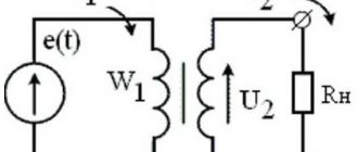
Helical windings (Figure 5) are wound from a number of parallel rectangular conductors (from 4 to 20), adjacent to each other in the radial direction. If there are a large number of parallel conductors, they can also be located in each turn in several layers in the axial direction, or the winding is made multi-pass, that is, the parallel conductors are divided into 2 - 4 groups and each group forms an independent helical stroke of the winding.
| Figure 6. Schemes of partial transposition of parallel conductors |
When several parallel conductors are located nearby in the radial direction, the current is distributed unevenly between them, which causes an increase in losses. The reason for the uneven distribution of current is that such elementary turns, consisting of one parallel conductor, are coupled with magnetic fluxes of different values and different electromotive forces (emf) are induced in them. This difference in flux linkage is due to magnetic leakage fluxes that pass through the space occupied by the windings. In other words, we can say that the reason for the increase in losses is eddy currents induced by the magnetic field in the winding conductors and causing the surface effect phenomenon. As a result, the active resistance of the winding increases.
To ensure a sufficiently uniform distribution of current between the conductors, it is necessary to transpose (rearrange) the parallel conductors forming a turn (Figure 6). With complete transposition, each conductor occupies in the radial direction alternately all positions possible within one turn. Often only partial transposition of the conductors is performed. Transposition is carried out in several places along the height of the rod.
Low voltage windings are made with screw windings at Sst ≥ 45 kVA×A, Ist ≥ 300 A.
Marking
Marking is the first stage, which is carried out if materials and tools are available. Careful research is important to determine the technical specifications.
It is acceptable to do it manually using special tables (but note that in this case you will have to calculate everything yourself using formulas).
You can also select markup using programs - there are some available for free on the Internet. But in this case, a novice radio amateur will not be able to understand the calculation algorithm and learn how to perform the frame independently, without the use of computerized equipment.
How to do it manually
Testing of strength and fastening features is carried out experimentally. A coil is taken, or rather a sample of it, which you wouldn’t mind throwing away, and 10 turns are placed on it, which will be used for the main transformer.
A rod is selected with a diameter four times larger for wires with a thickness of 0.96 millimeters, five times larger if wires up to 1.56 millimeters are taken, and six times thicker if the wire thickness exceeds 2.44 millimeters. This must be taken into account; the selected instructions are available in special technical literature.
Separately, it should be taken into account that in addition to a certain bend, which certainly forms stronger in the first few layers, and then begins to round off, there is also a strong tension and stretching. When marking the frame, take into account that the multiplicity increases several times. For example, for a wire that is 1 millimeter thick, the radius of curvature will be about 5 millimeters. Radii for wires of any diameter are also placed in the corresponding tables.
Class selection
Carrying out markings according to samples allows you to avoid the appearance of loose and uneven surfaces in the winding. Thin getinax is used if it is necessary to increase the rigidity of the frame. For example, if the device power is up to 10 W, then the sizes of small parts will be 0.5, medium - 0.7 to 1.5, and large ones - from 1. Power up to 100 W implies the use of 0.7 - 1, 2, 0 - 4, 1 - 2 mm parts, respectively. For devices with power ratings from 100 to 500 W, take up to 1 to 2 mm for class a, from 3 to 6 for b, from 1.5 to 3 for class c.
For the latter type, with the highest power ratings, it is advisable to increase the radius of curvature by approaching the optimal rounding values. It is better to take special inserts made of material that is used for twisted magnetic wires. They are used if the thickness of the magnetic circuit is twice as thick as the working rod of the device.
Additionally, most of the protruding part of 3 millimeters is installed on the part. This is necessary so that the cheeks of the frame are firmly attached to the equipment. The sleeve is made slightly larger in size than the working rod by 0.5 mm, the gaps should not exceed this figure. Be sure to take into account whether the frame is obtained using hardware or whether it is supplied with the device.
Calculation using programs
There are several dozen programs on the Internet, most of them freely available, that calculate the transformer and its frame. In particular, the CARCASS program is popular, from version 1.0, 2.0 and onwards. It works online, but if you wish, you can download the file and install it on your computer. The program contains information about:
- core type;
- thickness of material and screed;
- core sizes A, B, C, N.
After entering all the information, press the “Enter” or “Calculate” button. The calculation will also appear on the coil line, which can be printed and applied to the available textolite. There is an option designed for a frame with a lock.
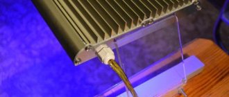
In my practice, I have always used only toroids as power transformers. But one day there came a time in life when I needed an audio output transformer. And not one, but two, and completely identical. There was a question about hardware. Having dug through a bunch of information in the trash heap on the Internet, I decided for myself that PL-iron is the best, and to obtain cores with similar parameters, you need to halve the SL-iron. For these purposes, the farm found OSM-250, half of which is shown in picture 1. A tie was immediately made for it - a strip of metal to which M6 studs were welded.
Iron:
What is the frame made of? It is clear that it is made of textolite. Where can I get it? You can, of course, in a store, but for this I need to go to another city. But relatives and friends bring packs of old radio equipment for disassembly (you just need to throw the cry correctly). In a word, the material has been chosen.
Frame material:
Next comes the question of marking the frame. It turned out that everything is not so simple here. There are different programs for these purposes. I looked at them too. Some people count well, but don’t draw; others draw, but count incorrectly. And I couldn’t find a single one that I could print to size. Maybe I was looking poorly. He went, like Lenin, a different way. I took a good old ruler and a caliper and took measurements of the core. Then I opened the good old Sprint Lay and hand-drew the vertical walls of the frame. I would like to draw your attention to the fact that you need to take into account the thickness of the PCB and the gap for installing the screed. The frame must have such an internal cross-section that it can fit freely onto the iron, and the two halves must not interfere with each other. I set the line thickness in the program to 0.3 mm.
Drawing of vertical walls:
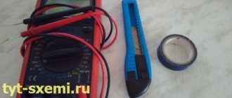
After the printer has printed everything beautifully, I take a utility knife, a metal ruler and cut out what was printed so that the line remains visible. Then, when finishing with a file, it is good to navigate along this line to give the workpieces sufficient accuracy. All that remains is to cut the textolite blanks to size, glue to them what you cut out of paper and modify them with a file. After that, using a needle file, I adjust the walls to each other and mark them.
I determine the size of the horizontal cheeks after the base of the frame is adjusted and assembled. Here the program is no longer needed - a caliper is enough. To install the output terminals on the “outside” side, I add about 7mm. I cut out the blanks, finish them with a file, and assemble the frame.
Assembled frame:
On the assembled frame, I round off the sharp edges with a file so that the wire does not break, and lay down one layer of paper (painting) tape. Beauty!
The next step is winding the wire and installing the terminals. Or vice versa. In my case, the windings are sectioned and there are many pins. It was difficult for me to determine in advance where it would come out, so I first wound it, then installed the terminals. Not important.
The question about the terminals is interesting. Again, anything can be used as them. While I was scratching my head about what to choose, my eye fell on the chassis of an old TV. And on it there are SKD and SKV blocks. And these blocks are held on by pins. Here is the solution to the issue. Looking ahead, I will say that it is a very beautiful solution. Well, how can you not praise yourself!
Pins:
So, I solder the pins. Their diameter is 1.5 mm, and the main value is that there is a collar. I mark and drill holes for the pins with a drill also 1.5 mm in diameter. From the inside, using a 3 mm drill, I carefully, without fanaticism, make a cone-shaped recess by hand. You don't have to do it, but it's better with it. You still need some emphasis. There is no way without him. I came across some kind of rod, in which I modified a 1.8 mm hole. But 1.6 mm is better. Next is the process itself: I insert the pin with the soldered side facing out, and use side cutters to bite off the excess inside, leaving a 1-1.5 mm tail. I clamp the stop in a vice, put the unbitten part of the pin on it and, using the tip of a small hammer, also carefully, without fanaticism, rivet the bitten off stub. The riveted material fits beautifully into the countersunk extension; a small brass bump remains on top, which does not interfere at all. Or it doesn't stay.
Believe it or not, it took about 15-20 minutes to install 28 pins.
Pin installation diagram:
This method does not claim exclusivity and certainly does not claim to be an invention. It’s probably difficult to call it technology, but some ideas will definitely be useful to someone, will lead to other technical solutions, and someone will use this or a similar method in its entirety or some part of it in their practice. I will be glad if this material is useful to someone.
Ready product:
Cutting
Cutting occurs after applying the coil drawing to the material. This is done using a regular construction pencil or even a marker.
The tools needed for cutting vary depending on the thickness of the PCB. For sheets up to 1.5 millimeters, whose cutting is carried out in a cold state, guillotine shears are used. And if the sheets are thicker, then a circular saw is used. Textolite with a thickness of 3 millimeters or more is sawed at a temperature of 80 degrees Celsius with a saw.
Calculations
Rice.
1: schematic diagram of a transformer The most difficult option if you make a transformer with your own hands from scratch. In this case, the calculation of the electric machine is made depending on the output power. Based on this parameter, the power of the primary winding is calculated. If you use a factory core, then you can consider these values to be the same; if you assemble it yourself, then P2 = 0.9 * P1
This is an approximate calculation taking into account core losses. Depending on the quality of the do-it-yourself blending, the power difference can range from 5 to 20%.
Depending on the power of the primary, the cross-section of the magnetic circuit is determined, which is calculated by the formula: S = √P1
It should be noted that the power for calculations is taken in Watts, and the core dimensions are obtained in square centimeters.
Next, the electromagnetic energy transfer coefficient is determined: k = f/S,
Where k is the transmission coefficient, f is the frequency of the AC mains voltage, S is the cross-sectional area of the magnetic core.
Based on the obtained coefficient, the number of turns in the windings is determined by the magnitude of the input and output voltages: N1 = k*U1, N2 = k*U2
These are approximate calculations intended for home use by radio amateurs. Factory transformers have a more complex calculation procedure, which is carried out according to reference books and depends on their type and purpose (power, measuring, three-winding, toroidal devices, etc.)
Next, the current in the primary winding of the transformer is calculated: I1 = P1 / U1
Accordingly, the current flowing through the secondary winding of the transformer is calculated by the formula:: I2 = P2 / U2
Based on the current value in each winding, the core cross-section is selected. But note that the conductor in the winding is cooled much worse, so the cross-section reserve is made by 20 - 30%. It is easier to do this work with copper wires, but this requirement is not critical.
Table: selection of cross section, depending on the flowing current
| Copper conductor | Aluminum conductor | ||
| Core cross-section, mm2 | Current, A | Section of veins. mm2 | Current, A |
| 0,5 | 11 | — | — |
| 0,75 | 15 | — | — |
| 1 | 17 | — | — |
| 1.5 | 19 | 2,5 | 22 |
| 2.5 | 27 | 4 | 28 |
| 4 | 38 | 6 | 36 |
| 6 | 46 | 10 | 50 |
| 10 | 70 | 16 | 60 |
| 16 | 80 | 25 | 85 |
| 25 | 115 | 35 | 100 |
| 35 | 135 | 50 | 135 |
| 50 | 175 | 70 | 165 |
| 70 | 215 | 95 | 200 |
| 95 | 265 | 120 | 230 |
| 120 | 300 | ||
Winding wires and installing terminals
The wires are wound onto a reel, then the terminals are installed after complete impregnation with varnish and final drying. The leads and bends are made with a slightly larger section. Multi-core insulated wire is suitable; it is better to use color markings.
The coil is clamped between the cheeks, the pin is mounted in the cones. The winding equipment is installed at least one meter. The machine rotates so that the wire lies on top, hold it in the direction with your left hand. The terminals are installed after insulation.