The tangible cost of electrical equipment makes purchasing quite difficult for poor people. The need to perform welding work forces you to make the oscillator yourself to save material resources.
Sometimes in production or at home there is a need to connect parts made of non-ferrous metal or stainless steel. It is possible to use a homemade oscillator simultaneously with the welding machine. The use of a simple device will allow you to avoid temporary losses in cleaning products.
Why do you need a homemade oscillator?
The oscillator as a generating device is capable of operating on direct and alternating current. The purpose of the device is to excite the welding arc without contact of the electrode with the welding object and stabilize combustion. The type of electrode: tungsten torch tip or standard coated tip does not matter. The effect is achieved by transforming the mains current into high-voltage frequency pulses, with the following parameters:
- Mains voltage 220 V - output voltage - 2.5–3 thousand V;
- Current frequency 50 Hz - output frequency - 15–30 thousand Hz;
- Oscillator power – 250–400 W.
Electrical circuit of the oscillator
The operating principle of a homemade oscillator included in the welding device circuit with a degree of simplification:
- Supplying mains voltage to the welding device;
- The voltage passes through the windings of the step-up transformer and begins to charge the capacitor of the oscillating circuit;
- The storage capacitor accumulates the high-frequency high-voltage discharge voltage;
- In parallel, the system control unit opens the gas valve;
- The control unit releases a pulse when the capacitor capacity is filled onto the spark gap, a breakdown occurs;
- The oscillatory circuit is short-circuited, and resonant damped oscillations occur that go to the welding arc;
- When a capacitor breaks down, the fuse opens the electrical circuit;
- When the voltage drops, the next discharge is formed;
- The arc flashes in a gas cloud 3–5 mm above the part;
- When the remote contact breaks, the control circuit duplicates the arc ignition pulse.
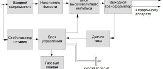
Functional diagram of the oscillator
This is interesting: Russian-made welding inverters - review of models
DIY oscillator for plasma cutter
An oscillator, which is easy to make with your own hands if desired, most often refers to continuous-action devices. Let's look at the design of the gadget.
In general, the oscillator consists of the following main components:
- oscillatory circuit . It plays the role of a spark generator of damped oscillations. The oscillatory circuit consists of the following components: storage capacitor ;
- inductor . Its role is usually performed by the winding of a high-frequency transformer;
Interesting: Do-it-yourself plasma torch
If you have the necessary tools, skills in working with electronic equipment and the desire to assemble an oscillator for a plasma cutter with your own hands, then you will have to assemble and configure the above components.
Scheme
To make it clear what you will create, we will tell you in general terms about the principle of operation of the oscillator. The mains voltage after the step-up transformer is supplied to the capacitor of the oscillating circuit and charges it. When the capacitor is charged to the optimal value provided for by the parameters of the electrical circuit, it is discharged through the spark gap (air gap breakdown).
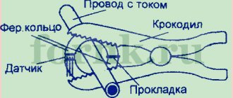
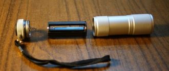
The appearance of a homemade arrester is shown in the figure.
Homemade single spark gap. East. https://met-all.org/oborudovanie/svarochnye/svarochnyj-oscillyator-svoimi-rukami.html.
The pulse that appears at this moment on the spark gap excites oscillations in the oscillatory circuit (oscillations represent the exchange of energy between the capacitance of the capacitor and the inductance of the winding of the high-frequency transformer). In the oscillatory circuit, damped high-frequency electrical oscillations arise, corresponding to its resonant frequency.
At the moment of resonance, a high voltage is generated on the capacitor plates of the oscillating circuit (the value depends on the quality factor “Q” of the oscillating circuit), which is supplied to the cutter through the separating capacitor and the coil winding and ignites. The parameters of the separating capacitor are selected in such a way that its reactance prevents the passage of low (mains) frequency current and does not interfere with high frequency.
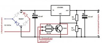
Here is one version of the circuit diagram of a homemade oscillator.
Schematic diagram of an oscillator that you can assemble with your own hands. East. https://ismith.ru/welding-equip/svarochnyj-oscillyator-svoimi-rukami/.
Explanations for the diagram:
1. Purpose of the MTX-90 indicator. At the moment the storage capacitor is discharged (provided the entire device is connected correctly), the “Phasing Control” display lights up.
2. S1 - arc former switch;
3. Choke Dr1 is a coil of 15 turns of wire with a cross-section of 2.5 square meters. mm, wound on a ring R40 x 25 x 80 made of ferrite with magnetic permeability M2000HM.
4. T1 – pulse transformer of a line scan generator (in slang - “line scan”) of the “TS180-2” type.
A big “plus” of this electrical circuit is the fact that its implementation does not require any scarce or expensive parts (materials).
It should be taken into account that the oscillator during operation, thanks to the spark gap, creates large electrical noise. To neutralize them, it is necessary to install all components in a “solid” metal casing.
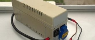
An example of the design is shown in the figure.
Interesting: How to make a homemade plasma cutter from a welding transformer
An example of installing an oscillator in a “solid” housing. East. https://m.radiokot.ru/forum/viewtopic.php?f=11&t=115840.
Setting up the oscillator should be carried out with the plasma cutter with which it will subsequently work. It consists in selecting terristors through experience. You should focus on the stability of the welding arc.
Attention! When setting up and subsequently working with the oscillator, you should strictly follow the safety rules when working with electrical appliances. The gadget is a continuous device with pulsed power, and voltage remains at its output contacts after the power is disconnected from the network.
Video
Watch a short video describing one of the DIY oscillator options:
Oscillator - what is it and what is it for?
The purpose of the oscillator is to ignite and stabilize the welding arc, regardless of the welding conditions. Moreover, this device is equally effective on welding machines of both direct and alternating current. The operating principle is based on spark generation of damped oscillations.
The oscillator circuit is quite complex in terms of tuning techniques. However, it works according to simple laws of physics.
Next, the oscillatory circuit comes into operation, generating a high-frequency current. The internal windings switch to high-frequency transformer mode. The conversion frequency is 150-200 kHz, and the voltage rises to 6000 volts.
High-voltage oscillator, what it is and how it works, see this video
Secondary characteristics indicate the safety of the oscillator. The power is no more than 250 W, and the duration of effective pulses is no more than 10-30 microseconds. In this case, the arc is excited, and upon contact with a person, a current dangerous to life does not flow.
According to the method of exciting the arc, there are two options for the operation of the oscillators
Continuous action
Integrated into the power supply of the welding machine. The arc is excited by applying high frequency current directly to the power cables of the device. After which it does not matter what current the main power supply will produce. The arc still remains stable.
Pulse action
Connected in series to power cables. The system is not so complicated; there is no need to install chokes that shunt high voltage and protect the welding machine. Works effectively with AC welders. The arc burns stably when the direction of the current changes in each half-cycle.
The common element is a blocking capacitor. It is selected in such a way that high-frequency current (generated by the oscillator) flows freely through it, and the standard current from the power supply is blocked. This circuit guarantees galvanic isolation between the oscillator and the power supply transformer.
Homemade oscillator
You can construct an oscillator for argon welding with your own hands. At the moment there are many schemes. We will look at one of the simplest ones. The main element of the structure is a high-voltage transformer, which increases the voltage from 220 W to 10,000 W. A rather important condition in the manufacture of a home-made device is the precise design of the spark gap, because it is this that is responsible for the quality of annealing. The development of a spark gap is the main difficulty in creating a homemade one, because it is in it that an electric spark occurs.
Schematic diagram of the OSP3-2M oscillator.
In addition to all this, the design includes a blocking capacitor and an oscillating circuit. This can be seen from the diagram shown in the image. In order to make it yourself, you need to select all the components correctly and approach this task wisely. A standard oscillator can be designed as a generator, the transformers of which increase the voltage frequency to 3000 W. The arrester must be present in this product.
A welding oscillator made independently can operate in two modes: pulsed operation or continuous operation. In the second case, it is worth using protection against high voltage levels. The option of implementing impulse work is one of the most effective in comparison with similar ones. The most important thing to remember when building a welding oscillator is safety precautions.
Welding process sequence
Despite some differences in the assembly, the use of devices of this class follows the same scenario. You can imagine the sequence of operation of the device like this:
- The welder on the torch presses the “Start” button.
- The rectifier at the input receives voltage from the network, rectifies it and sends it to the storage device.
- The storage unit is charging.
- After the storage capacitor is triggered, the pulse is released.
- The pulse enters a high-frequency transformer and is converted into a high-voltage pulse.
- At the same time, the gas valve is activated and argon comes out of the argon-containing chamber.
- After a short discharge of current, the arc is ignited in the gas cloud and the welding process begins.
- When the welding current begins to work with a force exceeding five amperes, the pulse fades. The welding process takes place with the values set on the machine. When contact is lost, the next impulse occurs to revive the arc.
- When welding ends, the device ends the process.
When making an argon burner with your own hands, the design can be simplified and the device becomes semi-automatic. In this case, if the welding process is accidentally completed, you must manually turn on the non-contact ignition by pressing the “Start” button.
How the oscillator works
Such devices may have different assembly options, but they are all designed for the same purpose - to excite a welding arc between the end of the electrode and the surface of the product at a distance of 5 mm, without physical contact with the materials. This is achieved by placing the oscillator between the welding current source and the torch with a tungsten electrode. Instead of the latter, there may be a holder for welding with coated electrodes.
The essence of the process is to upgrade the incoming AC voltage with a frequency of 50 Hz into pulses of high frequency and short duration. They are superimposed on the welding current and actively participate in igniting the arc. The oscillator for welding, in most circuit variants, operates in the following sequence:
- The welder presses the control button on the torch.
- The input rectifier receives voltage from the network with parameters of 220 V and 50 Hz. The device rectifies the current and transfers it to the drive.
- The storage capacity collects the discharge.
- The control scheme guides this process. When the mains voltage reaches 0V, a pulse is released for subsequent generation.
- It enters the primary winding of the transformer, where it is converted into a high-voltage pulse.
- At the same time, the control circuit sends a signal to the gas valve and argon is released.
- A short discharge of current occurs, connecting in the air the voltage from the torch and the product to which the mass from the welding machine is attached. The arc is ignited in the already prepared gas cloud, and welding can begin immediately.
- When a welding current with a force of more than 5 A is turned on in the process, the pulse stops its action. Welding is carried out using the parameters that were set on the machine. If contact is lost, the control circuit sends a second pulse to restart the arc.
- After welding is completed, the oscillator adjusts the time of subsequent purging with shielding gas and completes the entire process.
This is very convenient for welding aluminum or alloy steels, where precision in the start of the weld is required, and mechanical cleaning of marks from touching the electrode leaves unnecessary marks. Making an oscillator with your own hands can be simplified to several units. Then, if the welding breaks, you need to start the non-contact ignition action manually by repeatedly pressing the button on the torch.
Design and principle of operation of the equipment
To understand the nature of the functioning of the device, you need to have a good knowledge of physics. The arc obtained when the oscillator is turned on does not change its parameters as the gap between the electrode and the workpiece increases.
The oscillator design includes the following elements:
- Step-up transformer. Used to change the voltage amplitude.
- An oscillatory module with a standard structure. It includes capacitors and inductive coils. The circuit is used to create high-frequency oscillations.
- The spark gap is an air gap in which a spark appears.
The device can be supplemented with sensors that automate the operation of the equipment and help control it. If the oscillator is included in the argon arc apparatus, it is equipped with a gas inlet valve. The microprocessor issues a command to open the element at the right moments. The oscillator is equipped with a safety system that prevents the device from malfunctioning.
The capacitor protects the welder from electric shock. In the event of a breakdown of a part, a fuse is activated, breaking the circuit when the current surges.
Assembly at home
To assemble a do-it-yourself argon welding device from an inverter, a common and simple circuit is most often used.
In this circuit, the main element is a step-up transformer. It is he who increases the standard voltage to three thousand volts. The most problematic component when assembling this device is the spark gap, which produces a strong spark. The spark gap and inductor provide the main thing - they generate damped high-frequency pulses that ignite the arc and maintain uniform combustion. The coil and spark gap together with the blocking capacitor form an oscillatory circuit unit.
Homemade devices can also be made according to two different schemes. They can be pulsed or continuous. Devices using the principle of continuous operation are less efficient and a voltage protection unit must be included in their design. Pulse devices are considered better, more convenient and more productive.
The main part of the control unit is the button. It performs two functions: turning on the spark gap and controlling the supply of shielding gas to the welding area. The primary data for self-assembly are detailed answers to the following questions:
- Application for aluminum or stainless steel.
- Type of electric current - alternating or direct.
- What voltage is provided?
- What power will the device be designed for?
- What is the value of the secondary voltage.
The parts are assembled on a rectangular board. On the left there is usually a high-frequency transformer, a control unit and a safety unit. In the central part it is logical to place a spark gap with an oscillating circuit capacitor and a blocking capacitor. The latter becomes an obstacle to low-frequency current on the way to welding. There is space on the right for the throttle.
The transformer is selected based on the current requirements in the secondary winding. In this case, it is better to make the inductor double. Then the voltage and current are more stable, and the protection of the device is more reliable. The contours are similar to each other and consist of:
- A capacitor, the voltage reserve of which in the first part should be at least 500V and 5–6 kV for the second. The capacitance of the first capacitor must be at least 0.3 mF, and the second up to 1 mF.
- Varistor with a voltage in the secondary winding of about 90–100 V (for the first stage) and up to 140–150 V in the second line.
- Inductors. Both coils have a ferrite rod with a copper wire wound on it with a cross-section of about 20 millimeters square with a gap of at least 0.8 millimeters. In the first cascade the number of turns is from seven, and in the second - less. The coil of the second stage is a filter and protection against current fluctuations. Current of different amplitudes can lead to unstable combustion.
For the spark gap, a board with heat sink fins is found. This board cools when the discharge is triggered. Tungsten electrodes are sometimes replaced with conventional ones. The main thing is that their diameter is at least two millimeters. The tips of the electrodes must be strictly parallel. Using a special screw, it is possible to adjust the distance between the electrodes.
To obtain maximum stability, a coil from any stun gun is connected to the second winding of the second stage. To do this, you have to connect a six-volt battery to the device circuit. It provides power to this coil.
The presence of a battery does not allow you to forget that from time to time the entire device needs to be inspected and routine maintenance carried out. The first stage is connected to the inverter, and the second is intended for the welding torch and the workpiece that needs to be welded. The device body must have ventilation holes and be waterproof.
This is interesting: Do-it-yourself transformer for welding: types, diagram and assembly
According to the method of exciting the arc, there are two options for the operation of the oscillators
Continuous action
Integrated into the power supply of the welding machine. The arc is excited by applying high frequency current directly to the power cables of the device. After which it does not matter what current the main power supply will produce. The arc still remains stable.
Pulse action
Connected in series to power cables. The system is not so complicated; there is no need to install chokes that shunt high voltage and protect the welding machine. Works effectively with AC welders. The arc burns stably when the direction of the current changes in each half-cycle.
The common element is a blocking capacitor. It is selected in such a way that high-frequency current (generated by the oscillator) flows freely through it, and the standard current from the power supply is blocked. This circuit guarantees galvanic isolation between the oscillator and the power supply transformer.
Homemade oscillator for a plasma cutter: a little theory
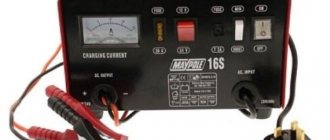
The appearance of the electronic unit of a factory-made oscillator is shown in the figure.
Welding oscillator brand VSD-02, used to stabilize the arc. East. https://met-all.org/oborudovanie/svarochnye/svarochnyj-oscillyator-svoimi-rukami.html.
Modern oscillators are divided into two classes of action:
- continuous action . This class adds a high frequency current (150...250 KHz) and a high voltage value (3000...6000 V) to the welding current. Under such conditions, the arc will ignite even without the electrode touching the surface of the workpieces being connected. Moreover, it will burn very steadily even at low welding current values (due to the high frequency of the current generated by the oscillator). And, what is also important, electricity with such characteristics is not dangerous to the health of the worker working on this device;
- pulse . The electrical circuit of this class may provide for its parallel or serial connection.
Examples of electrical circuits are shown in the figure.
Parallel and serial connection of the oscillator. East. https://met-all.org/oborudovanie/svarochnye/svarochnyj-oscillyator-svoimi-rukami.html.
Devices that are connected to the electrical circuit of the plasma cutter in series are more effective. This is explained by the fact that their circuit does not use high voltage protection as unnecessary. The use of an oscillator, in addition, allows you to expand the options of the plasma cutter and process “problem” metals or alloys:
We understand the design and principle of operation of the oscillator
Welding oscillators, capable of working with AC and DC sources, are needed in order to simultaneously increase both the magnitude of the voltage and the frequency of the electrical current. If the voltage at the input of such a device is 220 V and the current frequency is 50 Hz, then the output is already 2500–3000 V and 150,000–300,000 Hz. The duration of the pulses created by the oscillator is tens of microseconds. The power of these devices, with the help of which high-frequency current and high voltage is supplied to the welding circuit, is 250–350 W.
The technical capabilities that the oscillator has are provided by its design and the characteristics of its elements.
» data-lazy-type=»iframe» src=»data:image/gif;base64,R0lGODlhAQABAIAAAAAAAP///yH5BAEAAAAALAAAAAABAAEAAAIBRAA7″>
» data-lazy-type=»iframe» src=»data:image/gif;base64,R0lGODlhAQABAIAAAAAAAP///yH5BAEAAAAALAAAAAABAAEAAAIBRAA7″>
The electrical circuit of the device consists of the following components:
- an oscillatory circuit acting as a spark generator of damped oscillations (such a circuit includes a capacitor and an inductor - the moving winding of a high-frequency transformer);
- arrester;
- choke coils in the amount of two pieces;
- step-up transformer;
- high frequency transformer.
Functional diagram of the oscillator
In addition, the oscillator contains elements that ensure the safety of both the device itself and the welder. Such elements include a capacitor, which protects the welder from electric shock, and a fuse, which opens the electrical circuit if the capacitor breaks down.
The oscillator, which is used in conjunction with a welding machine, works according to the following principle. After passing through the windings of the step-up transformer, the voltage enters the capacitor of the oscillating circuit and begins to charge it. When a capacitor is charged to the value provided by its capacitance, it discharges a discharge to the spark gap, which leads to breakdown. After this, the oscillatory circuit becomes short-circuited, which causes the occurrence of resonant damped oscillations. The high-frequency current that forms these oscillations is supplied to the welding arc through a blocking capacitor and the coil winding.
An example of making an oscillator board
The blocking capacitor is designed in such a way that only high-frequency current, which also has a higher voltage value, can freely pass through it. Low-frequency current is not able to pass through such a capacitor due to too much resistance. Thanks to this characteristic of the blocking capacitor, low-frequency current from the welding machine cannot pass through it, which protects the oscillator from short circuits.
Oscillator assembly circuit options
When creating your own homemade oscillator, it is important to achieve the correct output parameters of the device. It should increase the voltage supplied to it from standard to 3000-6000 V. The change in oscillation frequency should be at a level from 150 to 500 kHz.
The oscillator circuit may include various components. Here is one of the options for the composition of the device:
- output rectifier;
- stabilized power supply;
- charging unit with capacity storage devices;
- Control block;
- block for pulse formation;
- high voltage transformer;
- current sensor;
- gas valve.
The oscillator is always installed in the circuit after the inverter or conventional transformer, and before the sleeve with the cable going to the burner or to the electrode holder. Individual blocks of the circuit are formed from parts purchased in the store or created independently. For example, an oscillatory circuit operating as a spark generator with damped oscillations is assembled from capacitors. And the inductor coil is the winding of the high-frequency transformer. The circuit must have a fuse that protects the welder from short circuits, and a special outlet for grounding the device.
How to use home equipment for beginners
The use of a homemade oscillator for electric arc welding of parts made of aluminum and other materials requires compliance with the following rules:
- The devices can be used both indoors and outdoors. If there is precipitation, the devices cannot be used outdoors.
- The operating temperature range of the equipment is -10…+50 °C. The oscillator can be used at air humidity of no more than 95%.
- The devices are used at atmospheric pressure of 85-105 kPa.
- Do not turn on devices in dusty or gas-filled rooms, or expose device elements to aggressive substances that can destroy metal and insulation.
- It is allowed to work only with grounded devices. Before starting welding, check that the oscillator is connected correctly to the electrical circuit and inspect the contacts.
- The protective housing can only be dismantled after disconnecting the equipment from the network.
- There should be no traces of dust, corrosion or soot on the surfaces of the device. If contamination appears, the elements of the device are cleaned with sandpaper.
Inverter add-on
In this case, along with basic safety precautions, observe the following rules:
- During the welding process, the functionality of the blocking capacitor is regularly checked. If this part is damaged, the operator risks electrical injury.
- The device is configured and adjusted only when disconnected from the network. The same applies to the process of cleaning surfaces from carbon deposits.
- The pulse frequency is constantly monitored. It should not be more than 40 μs.
For plasma cutter
The oscillator is configured in accordance with the parameters of the cutting device in combination with which it will work. Thyristors are selected experimentally, focusing on arc stability. When working with the device, carefully observe safety precautions.
The device continuously supplies pulses, so the current remains on the contacts even after disconnecting from the network.
The procedure for making an oscillator
If you have to weld mainly aluminum parts, then you can make a welding unit yourself. Installation is carried out using one of the most well-known schemes:
To begin with, a reliable transformer is selected that is capable of providing an increased voltage supply from the standard 220 to 3000 volts; Then it is necessary to install a spark gap that will allow a spark to pass through; This is followed by the addition of another important element. This is an oscillatory circuit with a blocking capacitor, which is capable of generating high-frequency pulses to achieve the required performance.. https://www.youtube.com/embed/zX2-HEv-Bhw
The oscillator is ready for use; its main element is the oscillatory circuit. A blocking capacitor must be present. All this helps create the necessary impulses. As a result, the welding arc is stable and the ignition process becomes easier.
The work process is quite simple. After startup, the spark gap starts to light up, creating frequency pulses. The high voltage transformer is responsible for this. A highly magnetic field is produced through the arc, then transformed by a coil made by winding welding cable. The plus goes to the burner, and the minus goes to the part, as a result, gas will flow through the valve into the burner. The welding process begins.
Before creating such a device, you should carefully read the drawings. Even basic knowledge of electrical engineering, coupled with design skills, will help you produce this oscillator without serious problems.
It is also important to follow safety precautions and remember the possibility of electric shock.
Manufacturing of key parts
Creating an oscillator for welding with your own hands begins with assembling the main elements:
- Step-up transformer. You can buy a ready-made part or make it yourself. The number of turns and the thickness of the core are selected depending on the operating parameters of the future device. When winding, take into account that the unit must increase the voltage to 6000 V.
- Oscillatory module. It is made of an inductor coil, which includes a ferrite core and a power cable wound around it. For the primary winding, 1 turn is enough, for the secondary - 5. The circuit is equipped with a spark gap and a protective capacitor. The first is used to develop and release a weakening impulse. The arrester is made of copper rods and tungsten rods that transmit current. Areas in contact with wires are coated with a hardening dielectric compound.
The oscillating module is connected in series with a capacitor. After this, a spark gap is installed, connected to the primary winding of the transformer. The capacitor can be purchased or taken from a non-working TV. To generate a more stable voltage, a dual inductor is used. In addition, this approach prevents device failure.
Both parts of the circuit consist of the following components:
- capacitors with a capacity of at least 0.3 mF;
- varistor with a voltage corresponding to that on the secondary winding (90-150 V);
- a ferrite rod onto which a copper core with a cross section of 15-20 mm² is wound.
Ignition coil oscillator
The most accessible circuit is performed on a car ignition coil.
However, the characteristics of the reels are not entirely suitable for such a purpose. Therefore, careful selection of the remaining elements of the circuit is required. You can use several combinations of thyristors until you are sure that the arc is reliably excited. Despite the temptation to make a simple oscillator, this is not the best circuit.
Avoiding common mistakes
Compliance with the following recommendations helps to eliminate the occurrence of problems in the operation of a homemade device:
- When assembling simple circuits, it is not always possible to maintain a stable arc. The cause of the malfunction is low voltage in the electrical network. Installing an autotransformer helps eliminate the occurrence of malfunctions in the operation of the welding unit.
- Don't skimp on the throttle. The spark gap supplies a series of damped high-frequency oscillations with a voltage of 1000 V. The secondary winding, which does not have a choke, receives up to 50 V. Because of this, a short circuit occurs. The current coming from the network begins to heat the transformer. To prevent the welding machine from malfunctioning, install a choke.
- When forming the winding, insulating gaskets are used and the cores are impregnated with bakelite varnish.
- A current frequency of 150-300 kHz is considered safe. If a person becomes a conductor, the current does not affect the functioning of internal organs, but causes superficial burns. Proper grounding helps to avoid a traumatic situation.
- The oscillating circuit must be equipped with a blocking capacitor.
Before assembly, it is recommended to consult with a specialist who will find out whether the chosen scheme is safe.
Compound
With such characteristics, a do-it-yourself aluminum oscillator has the capabilities that correspond to welding production or repair work in everyday life. It can be used to weld aluminum and other metals.
Let's consider the electrical components of the oscillator:
- arrester;
- two chokes;
- transformers: simple and high-frequency;
- oscillatory circuit.
A circuit consisting of a capacitor and a high-frequency transformer generates damped sparks.