DIY current clamps
I would like to draw your attention to the fact that the voltage at the output of the current transformer will be bipolar even if a pulsating unipolar current flows in the measured circuit.
A transformer cannot transmit DC voltage. It will transfer only the alternating component of the measured current to the output winding. One more note. The secondary winding shunt must pass electric current in both directions. It is unacceptable to place a diode in series with the output winding. This can lead to voltage surges on this winding, saturation of the transformer, interference in the measured circuit, and diode breakdown. You can first install a shunt resistor, and only then remove the voltage from it through a diode, or install a bridge with a shunt resistor included in its diagonal. The bridge, as is known, has bidirectional conductivity on the side of the AC inputs.
Here is a selection of materials for your attention:
TO
design of power supplies and voltage converters Development of power supplies and voltage converters. Typical schemes. Examples of finished devices. Online payment. Opportunity for authors
P
practice of electronic circuit design. The art of device design. Element base. Typical schemes. Examples of finished devices. Detailed descriptions. Online payment. Opportunity for authors
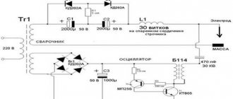
In some cases it is useful to measure the sum of currents through several conductors. Then all these conductors are passed through the core window. The current strength in the secondary winding will be proportional to the strength of the sum of the currents. The direction of current flow is important. If one wire is passed so that the current flows in one direction, and the second so that the current flows in the opposite direction, then the output will have a difference in currents. As I already wrote, a current transformer works better with a symmetrical measured current. In some cases this can be achieved by running the conductors in the correct direction. For example, in a push-pull voltage converter, a current transformer may be used to limit the current. You can pass the conductors connected to the collectors (drains) of the transistors so that the current passes through the transformer in one direction, but you can pass them crosswise, and apply the measured voltage to the bridge. Then the current transformer will operate in a more gentle mode.
Description of the design of homemade current clamps
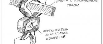
To assemble the device you will need a sensitive Hall sensor, for example, UGN3503. Figure 1 shows the device of a homemade pliers. You need, as already mentioned, a Hall sensor, as well as a ferrite ring with a diameter of 20 to 25 mm and a large “crocodile”, for example, similar to the one on the wires for starting (lighting) a car.
The ferrite ring must be accurately and accurately sawed or broken into two halves. To do this, the ferrite ring must first be filed with a diamond file or an ampoule file. Next, sand the fracture surfaces with fine sandpaper.
On one side, glue a gasket from drawing paper to the first half of the ferrite ring. On the other side, stick a Hall sensor on the other half of the ring. It is best to glue it with epoxy glue, you just need to make sure that the Hall sensor is in good contact with the fracture zone of the ring.
The next step is to connect both halves of the ring and wrap it around it with a crocodile and glue it. Now, when you press the crocodile handles, the ferrite ring will diverge.
Design
You can make a “current clamp” for a regular multimeter yourself if you have a sensitive Hall sensor, for example, UGN3503. Figure 1 shows the design of a homemade “pincer”.
You need, as already mentioned, a hall sensor, as well as a ferrite ring with a diameter of 20-25 mm and a large “crocodile”, for example, to connect something to a car battery.
The ring must be accurately and accurately broken into two halves. To do this, the ring must first be filed with a medical file for ampoules. Then, treat the broken surfaces with fine sandpaper. On one side, stick a thick paper gasket (drawing paper) onto one of the halves of the ring. On the other side, stick a Hall sensor onto one of the halves of the ring.
It is most convenient to glue with epoxy glue, but so that the sensor fits tightly to the place where the ring breaks. Then, folding both halves of the ring as shown in Figure 1, they need to be inserted into the “crocodile’s mouth” and glued to the “crocodile’s jaws” with the same epoxy glue.
The result should be a structure schematically shown in Figure 1. When pressing on the “crocodile” handles, the ferrite ring should open along with its “jaws”.
Rice. 1. Design of homemade current measuring (current) clamps.
Description of the design of homemade current clamps
To assemble the device you will need a sensitive Hall sensor, for example, UGN3503. Figure 1 shows the device of a homemade pliers. You need, as already mentioned, a Hall sensor, as well as a ferrite ring with a diameter of 20 to 25 mm and a large “crocodile”, for example, similar to the one on the wires for starting (lighting) a car.
The ferrite ring must be accurately and accurately sawed or broken into two halves. To do this, the ferrite ring must first be filed with a diamond file or an ampoule file. Next, sand the fracture surfaces with fine sandpaper.
On one side, glue a gasket from drawing paper to the first half of the ferrite ring. On the other side, stick a Hall sensor on the other half of the ring. It is best to glue it with epoxy glue, you just need to make sure that the Hall sensor is in good contact with the fracture zone of the ring.
The next step is to connect both halves of the ring and wrap it around it with a crocodile and glue it. Now, when you press the crocodile handles, the ferrite ring will diverge.
Operating principle of current clamps
Current clamps are a regular current transformer, only dismountable. The conductor in which we measure the current is passed inside the core. Next, the pliers collapse and the core closes. The handle of the current clamp contains a secondary winding wound on this collapsible core.
Such current clamps allow you to measure the strength of alternating current. To measure direct current, a slightly different principle is used. Description of DC current clamps.
DC current clamp - do-it-yourself multimeter attachment. Description
To measure large currents, as a rule, a non-contact method is used - special current clamps. Current clamp is a measuring device that has a sliding ring that covers an electrical wire and the amount of current flowing is displayed on the device indicator.
The superiority of this method is undeniable - in order to measure the current strength there is no need to break the wire, which is especially important when measuring large currents. This article describes a DC current clamp , which is quite possible to make with your own hands.
What to remember
It is important to remember that all work on the construction and maintenance of electrical networks, as well as carrying out electrical measurements, must be performed only by specially trained personnel who have all the necessary permits and work orders for performing work under voltage. Follow the electrical safety rules, namely: use shoes with rubber soles (insulating galoshes), use insulating rubber gloves, work with a partner.
In addition, avoid touching live parts with bare parts of your body and prevent the formation of an electric arc. If you are not a certified specialist and work without a partner and a work order, you completely assume all responsibility for possible damage and injuries that you may receive in the process of performing them. Electricity is dangerous to life, it is important to remember this and follow all safety measures. Especially when it comes to carrying out work in switchboards. After all, the current strength in them is higher than in the home network, as well as the voltage. This is where current clamps are mainly used. Do not neglect the opportunity to seek help from trained specialists, do not risk your life in vain. If you still decide to carry out such work yourself, study the video, carefully read the instructions on how to use current clamps, and only after that, in compliance with all safety measures, proceed to work. How to use a clamp meter video, see below:
Current clamps. Device and types. How to choose
Current clamps are used to measure the electrical parameters of a power circuit in the form of phase angle, power, voltage or current, without disrupting the functioning of the circuit or breaking it.
Current clamp meters, which are clamp-on ammeters for measuring alternating current, have become very popular. They are designed for prompt measurement of current in a wire without taking it out of service and without breaking the circuit. Electrical clamps are used in electrical installations up to 10,000 volts.
Design and operation
A simple clamp meter model operates on the principle of a single turn current transformer. Its primary winding is the wire or bus being measured. The secondary winding, which has many turns, and is connected to the ammeter, is made on a split core.
a) – simple clamps using a 1-turn transformer. b) – clamps with a rectifier and a 1-turn transformer.
- Measured wire.
- Split core.
- Secondary winding.
- Rectifier.
- Measuring frame.
- Shunt resistance.
- Mode switch.
- Lever arm.
Clamp meters consist of three main elements:
- Working part: measuring device, transformer windings, magnetic circuit.
- Insulating part: from the handle stop to the working part.
- Handles: from the edge of the pliers to the stop.
To enclose the conductor being measured, the magnetic core can be opened by analogy with simple pliers, when hand force is applied to the insulated handles of the pliers.
Alternating current flows through the measured conductor, which is covered by a detachable magnetic circuit. In this case, the current forms a magnetic flux in the magnetic circuit, which creates an electromotive force in the secondary winding of the measuring clamp. When exposed to EMF, a current appears in the secondary winding, measured by an ammeter located in the measuring clamp.
Modern measuring devices operate according to a circuit that includes a current transformer with a rectification bridge. In this case, the output of the secondary winding is connected to an electrical measuring device using a set of shunts.
Varieties
Current clamps are divided into two types according to operating voltage and device:
- In electrical installations up to 1 kV, one-handed .
- In electrical installations 2-10 kV, two-handed .
One-handed electrical clamps combine a handle with an insulating part in their design. The magnetic core is opened using a special pressure lever. One-handed measuring clamps up to 1 kV can be of various sizes, and do not have specific size standards. You can use these pliers with one hand.
Two-handed measuring clamps for electrical installations from 2 to 10,000 volts have an insulated part size of at least 38 cm, handles over 13 cm. The design of such clamps allows for using the clamps with two hands.
According to the type of indicator, current clamps are divided into:
- Analog . They have a pointer display with a scale.
- Digital . Equipped with a liquid crystal screen.
Pointer ( analog ) measuring devices have not yet lost their popularity, despite the widespread use of digital instruments. Their advantage over digital devices is that they do not require a power source to operate.
To measure the starting current, it is much more convenient to use analog clamps, since they respond very quickly to a sudden change in the value of the electric current. In terms of the convenience of issuing measurement results, analog clamps are much inferior to digital devices, since the measured value can only be determined using a graduated scale.
Digital measuring devices are most convenient to use, since the measurement results are shown on the screen in digital form. Their disadvantage is the need for an auxiliary power source in the form of rechargeable batteries or batteries, as well as an increase in measurement error when the power source is discharged and electromagnetic interference.
According to the type of circuit parameter being measured, electrical clamps are divided into:
- Phase meters.
- Wattmeters.
- Ampere-voltmeters.
- Ammeters.
- Megaohmmeters.
Phase meters are devices that can measure the phase shift angle in a three-phase electrical network during operation of electrical equipment. In other words, this parameter is called power factor. Phase meters can be digital or electrodynamic.
Wattmeters , made in the form of measuring clamps, are used to measure the parameters of 3-phase and 1-phase networks in a non-contact way: reactive and active power. Most often, such devices are made in the form of a universal device that allows you to measure other parameters.
Ampere-voltmeters and ammeters in the device of electrical clamps function similarly to other types of clamps. They measure parameters of current, voltage in a certain circuit, or several parameters simultaneously.
Operating principle
What are clamp meters used for?
They are a type of electrical tester with wide jaws that can pinch the electrical conductor. They were originally developed as a general-purpose instrument for measuring alternating current. However, as their design improved, clamps included inputs for receiving test leads and other sensors that support a wide range of measured values. Indispensable as a testing tool, meter clamps make it easier to work in confined spaces and allow you to work on live conductors without interrupting the circuit. Being a high-precision meter, pliers cannot be made in non-specialized workshops or with your own hands.
The measuring clamps implement the principle of magnetic induction, which allows you to determine the current value in a non-contact manner. Electric current flowing through a conductor induces a magnetic field around it. Since the polarity often changes, dynamic oscillations of the magnetic field occur, which are proportional to the current strength.
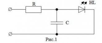
All sizes of current clamps operate using the Hall effect - the presence of transverse voltage that occurs when a conductor is placed in a magnetic field. Inside the housing there is a transformer that determines the intensity of magnetic oscillations, converting their value into an indication of alternating or direct current. Therefore, even if the resulting potential difference is small, the sensor will detect a magnetic field. This voltage, which is proportional to the current, is then amplified and measured (see Figure 1). Very powerful currents are measured in this way.
Figure 1. AC current measurement circuit
How to measure current using a transformer
When a conductor is passed through the terminals of the device, current passes through these terminals, acting as the iron core of a power transformer. Next, the current flows into the secondary winding, which is connected through the meter input shunt. Due to the ratio of the number of secondary windings to the number of primary windings wound around the core, the current entering the input is much less. Typically, the primary winding consists of one conductor, around which the jaws are clamped. If the secondary winding has, for example, 1000 turns, then the current in the secondary winding will be 1000 times less than that flowing through the primary winding. Thus, 1 ampere in the conductor being measured will produce only 1 milliampere at the instrument input. By increasing the number of turns in the secondary winding, powerful currents can be easily measured.
How to measure direct current, because it flows through conductors with a fixed polarity? Here the magnetic field around the conductor does not change, and it is impossible to record the corresponding readings in the usual way. Therefore, the clamps around such a conductor are closed with some gap (see Figure 2).