Why do you need an RCD?
First of all, a residual current device (RCD) protects a person from electric shock when accidentally touching a bare wire, the housing of faulty electrical equipment, or another conductive surface that is energized.
Another important purpose of the RCD is to protect housing from possible fire and fire in cases of violation of the protective insulation of electrical wiring.
To better understand why and, most importantly, how the RCD performs its protective functions, it is necessary to understand the principle of its operation.
Selection of protective device and circuit breaker
When choosing a machine for your apartment, you need to consider many factors.
- The first thing to consider is the needs of the home. The connection diagram of an enterprise and a residential premises is very different from each other. Accordingly, the machines will be different, with different loads.
- When choosing between manufacturers, try to choose a time-tested company. An ABB type RCD is perfect for your home. ABB are perfectly adapted for domestic networks and fit perfectly into any electrical circuit. In addition, you can do the connection of a two-pole circuit breaker yourself.
- Knowing the total maximum current, distribute the load among the branches. For example, a separate circuit breaker and RCD are installed for sockets. Separate electrical protectors are also installed for lighting. Thus, the scheme will be under reliable protection.
- When installing an RCD, it is necessary to take into account the cross-section of the wire. To do this, when consulting with a specialist, clarify which wire will be needed.
- The machine is inextricably linked with the protective device, which means it must meet the same parameters.
We advise you to study Lithium ion battery
If the connection is made correctly, the device will operate with small differences. But this does not mean that it should turn off on its own. Proper connection of a protective device to the circuit will help maintain health and prevent an emergency.
Operating principle of RCD
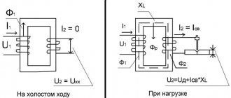
The operating principle of an RCD in a single-phase network is very clearly illustrated by the following diagram:
It shows a two-pole residual current device (1), to the upper terminals of which the phase (2) and neutral (3) conductors of the input electrical cable are connected, and to the lower terminals are the phase (4) and neutral (5) conductors going to the load, for example, to the electrical outlet to which the electrical appliance is connected - in this case, the water heater (6). To the body of which, directly, bypassing the RCD, a protective conductor is connected - grounding (7).
In normal, normal operating mode, electrons moving along the phase conductor pass through the RCD to the load - the heating element of the water heater then exits along the neutral conductor, also passing through the RCD and are sent to the ground. I1=I2
In this case, the currents entering the device through the phase conductor (2) and leaving it through the neutral conductor (3) will be the same in value, but opposite in direction. Now let's imagine that the insulation of the heating element is broken, and part of the electric current, through the coolant - water, begins to flow to the body of the water heater, and then through the grounding conductor (7), goes into the ground.
Now, the current entering through the phase conductor (2) is quantitatively equal to the sum of the current on the neutral conductor (3), still coming from the heating element through the RCD, and the leakage current leaving through the housing to the ground (7) I1=I2+I3 . Accordingly, the incoming current into the device is greater than the outgoing current by the amount of leakage current I1>I2 .
is based on this effect - it determines the difference between the value of the incoming current through the phase conductor and the outgoing current through the neutral conductor and, if it is above the operating threshold, the RCD immediately breaks the electrical circuit.
The operating principle of the residual current device is similar a bare live wire, in this case part of the current goes into the human body, the resulting leak is immediately detected by the RCD and turns off the supply of electric current. All this, as a rule, happens in a fraction of seconds and the person does not have time to receive serious injuries.
To understand how a residual current device detects current leakage, let's look at the device of a standard RCD.
Three-phase RCDs
The operating principle of three-phase devices is exactly the same as that of single-phase ones. Only through the transformer core there are not two windings, but four: one neutral and three phase. Here is the simplest diagram:
It clearly shows what the device consists of.
- 1 is a switch.
- 2 is the element that receives the shutdown signal.
- 3 is the secondary winding.
- 4 – transformer.
- 5 – power supply wires.
The RCD will operate immediately as soon as the balance of current values in the windings is disrupted. That is, a leakage current will flow through winding “3”. It will reset the signal to element “2”, which in turn will disconnect the consuming device from the network. Since the RCD operates in automatic mode, the nameplate value of the current plays a major role here.
RCD device
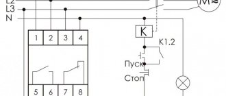
Below is a visual diagram of the RCD device, the main components of which include:
1.Residual current transformer
2. Electromagnetic relay
3. Electric circuit release mechanism
4. Verification mechanism
Number “5” indicates the load; it can be any electrical appliance, such as a water heater or washing machine.
Now let's look at how these elements participate in the operation of the RCD, how the underlying operating principle is ensured.
The phase and neutral conductors are back-to-back windings of a differential transformer (1); in normal operation, in the absence of leaks, they induce equal, counter-directed magnetic fluxes in the transformer core.
Accordingly, their total magnetic flux is zero, as is the current. In this case, the electromagnetic relay (2), connected to the secondary winding of the transformer, is at rest.
In the case when an electric current leak occurs, different currents will flow through the phase and neutral conductors, which will cause inequality of counter magnetic fluxes on the magnetic core of the differential transformer (1) and the formation of a current in the secondary winding.
If the generated current is sufficient, the electromagnetic relay (2) is activated and acts on the release mechanism (3), which breaks the electrical circuit.
The testing mechanism (4), in the design of the RCD, simulates a leak, thereby helping to check the performance of the device. It is designed quite simply, as can be seen from the diagram, it is a regular resistance - a load connected bypassing the differential transformer.
When you press the TEST button, the electric current from the phase wire, passing through the resistance, enters the neutral wire of the transformer winding, bypassing the measuring transformer. As a result, the current on the incoming phase wire and the outgoing neutral wire will be different; an unbalance current is formed on the secondary winding, which triggers the mechanism for shutting down the electrical circuit.
This diagram quite accurately describes the device of the RCD and, although the internal design of the units, depending on the model and manufacturer, may vary, the general principle of operation remains unchanged.
Now, knowing the internal structure, you can easily identify an RCD on single-line diagrams of electrical panels, because its symbol contains all the elements described above.
The procedure for connecting the RCD
To install the protective device, you must acquire a DIN rail, a distribution panel, and a circuit breaker.
During installation, safety precautions must be observed and proper tools must be used. You also need to check the RCD using the Operation Test button.
At the first stage, it is necessary to lay the wires that will be located behind the mounting rail.
The distribution of the power line begins with the input machine. In this case, it is recommended to install a two-pole 40A circuit breaker. After this, the phase and neutral wires are inserted into an electric meter at 50-60A. Further, if there is no fire protection RCD on the diagram, the phase conductor is routed to circuit breakers, RCDs, and is also routed to circuit breakers responsible for a group of sockets, and so on.
The neutral wire after the fire protective device is connected to the common neutral bus, and then connected to the RCD, and so on.
All wires are routed from the top. This action will not reduce the efficiency of the device, and if another electrician has to carry out repair work, you will not have to spend a lot of time figuring out what is where.
The most popular options:
- connecting a two-pole to an electric line having one phase;
- connecting a four-pole to a circuit having three phases using a neutral conductor;
- connecting a four-pole to a power line with three phases without the use of a neutral conductor;
- connection of a four-pole RCD in an electrical circuit, single-phase current.
Uzo designation on a single-line diagram
Currently, for each of the types of ouzo used in electrics, namely two-pole - in a single-phase network and four-pole in a three-phase network, there are two most common designations that are found in single-line diagrams. All of them are reflected in the image below:
For single-line diagrams, the RCD designation is made as simple as possible , everything unnecessary is removed from it, only a differential transformer in the form of a ring, a switch that breaks the contacts and the number of poles are shown.
At the same time, in order to make the designation as compact as possible, the poles can be reflected in the form of slashes, the number of which is equal to the number of poles. This is where two variants of RCD designations appeared on the diagrams.
The circuit is also, quite often, printed on the body of the residual current device, along with other characteristics; let's look at them in more detail.
Connection diagram
It should be noted that single-phase and three-phase devices must be installed in a distribution board in different ways.
Single-phase connection
The RCD in a two-wire network is installed below the input circuit breaker, but above the circuit breakers that are installed on separate circuits. In this case, the zero phase and the grounding circuit run as separate loops.
Attention! The RCD-automatic connection is a must. The thing is that the residual current device does not ensure that the network opens under current load (both short circuit and thermal load are taken into account here). These are handled automatically. By the way, recently both devices can be replaced with a so-called differential machine. But this is a topic for another article.
Three-phase connection
The difference between the operating principle of three-phase and single-phase ones is significant. A three-phase device protects both single-phase and three-phase consumers. That is, the RCD knocks out both if the insulation of a single-phase consuming household appliance is broken, and of a three-phase one. In this case, the phase circuit can be combined with the ground circuit.
RCD marking
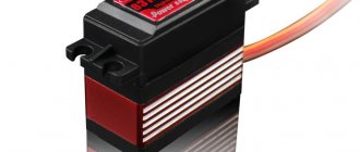
Let's look at what a standard two-pole RCD looks like when installed in a single-phase network.
Each residual current device has a marking that reflects all its main characteristics ; in addition, quite often, a diagram is also shown. Let's take a closer look at all the main characteristics of the RCD.
Types of RCD and its operating principle
There are 2 types of protective devices available. This is electromechanical and electronic equipment. They are identical in principle of operation. The main difference and advantage of the electromechanical device is:
- operation without power supply to the device;
- simplicity, reliability of the product design.
Leakage current when the insulation is damaged and touches the bare area causes the protection to operate - this is the principle of operation of each type of device.
A device with an electronic circuit, installed with power supply. The basis of its work is to create an impulse to the executing relay during leaks.
But if the power is turned off in the serviced section of the circuit, the device will not be able to work, because no current is supplied to it. Malfunctions occur in the operation of the electronic type ouzo in a three-phase network in severe frosts.
Therefore, such devices are rarely used, although their price is lower than that of electromechanical protection devices.
RCD CHARACTERISTICS
1. Manufacturer
2. Model name. In this case, the letters “VD” in the model name mean Differential Switch
3. Operating current. The maximum current value that this RCD can switch. In other words, if there is a load of 30A on the line that protects the RCD with an operating current of 25A, the device will fail.
4. Electrical network parameters. Here two main parameters are indicated for which this device is designed: voltage – 230V and frequency – 50Hz. These are standard characteristics for a household electrical network in Russia.
5. Leakage current. The magnitude of the leakage current at which the RCD will trip.
6. RCD type. In this case, this is an “AC” device, for alternating current. We will look at all types in more detail below.
7. Operating temperature range. From -25 to +40 degrees Celsius.8. Rated conditional short circuit current. This is the amount of possible current during a short circuit that the RCD can withstand without loss of functionality if it is protected by a circuit breaker of the appropriate rating.
9. RCD device diagram
Depending on the manufacturer, the markings on the devices may differ slightly, and some characteristics may be added or removed. But the basis is the same everywhere and such important indicators as operating current and leakage current are always indicated by everyone.
As you already understand, the abundance of indicated characteristics indicates that RCDs are different. In the next part of the article we will take a closer look at all the main types of modern RCDs and their areas of application. This information will help you choose the right differential current switch for each specific case.
Warning
Various parameters of the device are indicated on the body of the shutdown protection device. Many people choose it based on current strength with the unit of measurement in amperes (A). So here there is one rather important nuance.
Many people mistakenly believe that according to this indicator, the RCD is selected automatically in accordance with this indicator. That is, if the machine is selected at 25 A, then the RCD should have exactly the same parameter. Remember, the value printed on the device body determines the throughput. Essentially, this is the current load rating.
How to choose an RCD depending on the place of application
The device itself cannot protect the network from overloads or short circuits. This is not his purpose. This is exactly what the machine does. The device itself must be protected on the network. Therefore, the advice is to use a protective device in the circuit, which has a rated current load higher than that of the machine. In our case it’s like this: the machine has 25 A, the RCD has 32 A.
Protected single-phase circuits with and without grounding
A circuit that is grounded is considered safe. Today, all electrical circuits are equipped with special circuit breakers that are triggered as a result of a disruption in the normal operation of the network. The RCD reacts to changes in leakage current from one link to another.
If, after passing through the device, the current indicator is higher or lower, the RCD is triggered and cuts off the current supply to the subsequent link.
The RCD is connected to a single-phase network after a direct disconnection of the network. Connecting a single-phase RCD provides that the device is not protected from overload. Therefore, it is necessary to connect a circuit breaker to the circuit being created.
The RCD can be connected with or without grounding. In the event of breakdowns, the current entering the device body is reduced due to the winding resistance.
In this case, if a difference occurs, the flow of current through the RCD stops. Therefore, it is advisable to install such devices in front of the machines that are connected to the devices.
Advantages of using RCD:
- High security of the electrical network;
- The possibility of electric shock to a person is excluded;
- Increases the service life of equipment;
- Overload protection;
- High response speed;
- Long service life.
In most residential buildings there is no local grounding. This leads to an increased risk of current leakage. In turn, a person may accidentally touch a damaged section of the chain. Alternating current, passing through the human body, has a damaging effect on the tissues and cells of the body.
Three-phase RCD: purpose, selection criteria and installation features
Due to the widespread use of electrical appliances in everyday life and at work, there is a need to protect people from electric shock. A three-phase RCD is a special device that implements this function. The specified unit must be connected using special circuits, which will guarantee the efficiency of its operation.
Purpose and principle of operation
Three-phase residual current device (RCD)
A 3-phase RCD is designed to equalize the current that passes through the phase and neutral wires. In the absence of emergency situations, the indicated values are equal. Stable operation of electrical devices is possible because counter currents in the windings compensate each other. In the event of emergency situations, the protection device turns off the power to electrical appliances. This is observed when the insulation of wires is broken, which provokes the leakage of charged particles. As a result, the currents passing through the neutral and phase wires will have different values.
In every home, a situation can occur when an electric current penetrates the body of a washing machine or water heater. When the potential begins to flow to the floor, the 3-phase RCD will react and turn off the power to the devices. Therefore, when using this circuit breaker, you can be confident in your safety.
Connecting an RCD is relevant for powerful electrical appliances in the kitchen and bathroom. Condensation collects on their metal body, which together forms a potential conductor of electricity.
It’s good when protective shutdown is present on sockets, lamps and low-power household appliances. In the event of emergency situations, these consumers pose no less danger to humans.
Criteria for selecting a three-phase RCD
The operating principle of all RCDs in a three-phase network is the same, but these devices differ in design and operational characteristics. Therefore, when purchasing a specific model, you need to take into account many nuances.
Sensitivity
The main operational parameter of the 3rd phase RCD, displaying the period of time after which the protection will operate. It is optimal when the sensitivity of the device is 0.025 s. During this time, the electric current will not have time to cause cardiac arrest in a person.
The RCD can operate with or without an additional power source. In the first case, he directly takes part in the process of opening the electrical circuit. The presence of this mechanism increases the cost of the device, but also increases its sensitivity.
In the absence of an additional power source, the RCD is triggered in response to the differential magnetic field.
Current differential
RCDs designed for 3 phases are able to regulate the value of the differential current at which it is triggered. In the absence of this function, devices typically respond to 5 mA. This current indicator clearly indicates the presence of an emergency situation and the need to turn off the power supply.
Number of terminals
For a three-phase network, it is necessary to buy 4-pole RCDs. They are equipped with 8 terminals for connecting input and output cables. Three pairs are intended for connecting the working phase, one – zero.
Number of amps
In order for the residual current device to function at any current, it is necessary to choose a model where the number of amperes is significantly higher than that of the machine.
There are universal models on the market. They provide the ability to connect to multiple networks simultaneously. Despite this advantage, such units have many disadvantages. They are less sensitive, have a complex connection scheme, and are more expensive. Such models are suitable for enterprises, but not for private use.
Preparing to connect
Properly performed preparatory and installation work will ensure stable operation of the RCD.
Connection diagrams for a three-phase network
Diagram for connecting an RCD to a three-phase network
When installing RCDs, the following operating diagrams are used:
- Complete shutdown of the electrical circuit. One unit has the ability to de-energize all electricity consumers in the event of an emergency.
- Partial shutdown of devices. When emergency situations occur, only some consumers are de-energized.
The first connection scheme is used in apartment buildings. The device is installed near the electricity meter. If the RCD trips, the whole house is de-energized.
When using the second scheme, the protective mechanism is installed on a section of electrical wiring going to a specific room. Since all devices are connected in series to the circuit, when the RCD is triggered, only the “problem” consumer will turn off, while the others will continue to function.
The second version of the scheme can be implemented in a different way. The point of installation of the RCD becomes the beginning of the serial connection to the wiring, which allows for selective operation of the unit on certain groups of consumers. Also, a protective mechanism can be installed directly in front of the output device.
The need for grounding
Connecting an RCD with and without grounding
Old electrical networks belong to the tn-c system, where there is no neutral conductor to enable grounding. In this case, protection must be provided separately for the home or equipment, which ensures safe drainage of currents. If there is no grounding, installing a 4-pole RCD is prohibited.
The correct connection diagram to the electrical network requires compliance with the following rules:
- The grounding conductor is connected only to the output cable. Connecting directly to an RCD is not permitted.
- If you have a single-phase network, you cannot use a four-pole device.
- Connection to a B3 type network is prohibited.
The grounding conductor is a separate element. The absence of additional terminals in the RCD for its connection only indicates this.
Connecting the residual current device
It is not difficult to install an RCD if you have basic information about the operation of electrical equipment. The manufacturer attaches a technical data sheet to each device. It specifies the recommended wiring diagrams to be used during installation.
Search for zero phase
Using a test lamp to find the zero phase
Determining the zero phase is very simple experimentally. You need to take two wires and connect them to the ends of the light bulb socket. Its ignition is observed if it is connected to the phase. In other cases, nothing will happen.
Connecting a light bulb to two phases at the same time is allowed for a short period of time. It is also possible to close such a circuit only for a short period. Otherwise, there is a high probability of the circuit breaker tripping.
Phase connection
If you manage to find zero, you must immediately connect it to the appropriate terminals. The remaining three wires are working phases. They are connected in any convenient way, which does not in any way affect the functioning of the RCD.
Rules for connecting an RCD to a single-phase network without grounding: the best diagrams + work procedure
A single-phase electrical network is familiar to every household. Regardless of whether a private house or a municipal apartment is operated, users in any case actively consume electricity.
This type of energy, however, cannot be considered completely safe. Therefore, an urgent task seems to be connecting an RCD to a single-phase network without grounding - a special device that significantly increases the degree of safety when using electricity.
A general view of protective modules
Despite the construction of electrical wiring diagrams, carried out according to approved rules, the risk of electric shock always remains. Therefore, it is important to take care of safety in a timely manner.
Residual current device - this is how the abbreviation “UZO” is interpreted in technical language.
From the point of view of the design, it does not look the most complex among modern electrical equipment. Nevertheless, it performs the protection functions quite efficiently and reliably.
This is approximately what the functionality of the electrical system looks like, with the help of which effective protection of users of electrical networks is carried out, as well as protection of various household equipment
It should be noted that there are types of RCDs, based on which a specific protective circuit is organized in each specific case:
guaranteeing safety of touch; preventive technical damage; counteracting fire hazard.
Each device with specific functionality differs from other designs in operating parameters, in particular – rated current and cut-off current.
Appearance of a device with a low cut-off current. When operating household networks, such devices are used to protect people from unintentional contact with electrical potential in conditions of emergency current leakage.
The most sensitive device, of course, is the RCD, designed to block the power source in case people unintentionally touch live parts of the circuits. The current cut-off range for such devices is in the range of 10-30 mA.
The best diagrams for connecting an RCD
For lines of electrical networks for household purposes, the introduction of RCDs without “ground” is typical. The main share of circuit solutions in the household sector is precisely single-phase wiring, where in principle there are only two lines: phase and zero.
Features of circuits without grounding
The schematic diagram of an electrical circuit without grounding must be carried out taking into account the inclusion of automatic protection for “short circuit” (short circuit) and overload current.
This is an obvious factor, because individual RCD devices are not designed to protect against such phenomena. These devices only protect against leakage currents.
Automatic circuit breaker - something like this is usually installed in a circuit to organize a protective cut-off due to network overload. The design of the RCD does not imply this type of cutoff
The range of cut-off currents and technical characteristics of circuit breakers are somewhat different from the operating parameters of protective RCDs.
Meanwhile, there are universal cut-off devices that combine in one device the functions of a circuit breaker and protection against unintentional contact with live electrical buses.
Each protective device structurally involves switching both conductors of the supply cable - phase and zero.
At the same time, when installing electrical wiring, you should accurately connect the conductors to the working terminals. Incorrect installation can result in damage to the protection device, which will lead to the inoperability of the protection system as a whole.
Classic inclusion option
Depending on the technical load (number of household appliances) and the number of rooms, an apartment or house can operate a single complete network or a network consisting of several subnets.
The simplest at first glance scheme for including a device in a user network has its own nuances. Therefore, incorrect connection not only threatens the failure of the protective devices themselves, but is fraught with a dangerous operational situation
For the first case, one RCD device is usually sufficient to organize a protective shutdown. Based on the parameters of the current consumed or the total power consumed, in this case the protective device is selected according to the rated current and determined with the cut-off current.
For the second option, devices are implemented on each of the existing subnets. In this case, as a rule, all installed RCDs are supplemented with circuit breakers designed for the power consumption of a separate subnetwork.
This is roughly what the circuit solution for implementing an RCD in the classic connection version looks like. This simple wiring option provides protection for the apartment/home network as a whole - complete blackout
The classic design of the circuit diagram for switching on an RCD “without ground” is traditionally performed as follows:
The main power cable, consisting of two cores (phase, zero), is supplied to the machine. From the circuit breaker, both wires are connected to the electric meter. Next, from the electric meter, two power wires are connected to the input terminals of the RCD.
After the protective device, for the option without subnets, there is no need to install a backup circuit breaker, but in some cases experts recommend doing this.
If a circuit with subnets is used, then after the RCD, a separate machine must be installed on each branch.
Several modernized wiring with one RCD and a separate circuit breaker for each subnetwork. The principle of operation is almost the same as the “classic” one, but thanks to additional automatic devices, it is easier to determine the malfunction
Thus, the phase conductor extending from the protection device supplies the working networks through additional circuit breakers.
The neutral core, which also passes through the cut-off device circuit, is brought out to a common zero bus, from where it is distributed along the zero tap lines for connecting the load.
Which RCD connection circuit is better?
Better or worse scheme - these concepts are purely superficial. How effective this or that scheme can be is the question.
And here even a non-specialist understands that a multi-stage option, where different levels of protection are used, seems more effective than any other simplified version.
Also a kind of classic circuit version with the addition of an RCD with two linear circuit breakers. One of the machines is usually placed on the power line of powerful kitchen appliances, the second - on lighting and sockets in other rooms
Therefore, a power supply device diagram with subnets, when one common RCD and additional protection devices are used on each of the branches of the electrical circuit, clearly looks preferable.
The construction of such a circuit, as a rule, involves the installation of a main protective device with a cut-off current of 100-300 mA. And additional devices distributed over separate branches of the common circuit have a cutoff current of no higher than 30 mA.
In this way, double protection is provided - fire protection and in case of unintentional contact.
A circuit solution where two RCD devices and one differential circuit breaker are used. Wiring here is also carried out “without ground” with the separation of power circuits due to additional automatic devices
We recommend: Voltage stabilizer
The advantages of building a power network in this way are also manifested in the fact that in the event of an alarm, only a separate section of household electrical wiring is usually turned off, and not the general power zone. Under such shutdown conditions, detecting the location of the current leak is much easier.
On the other hand, the so-called extended circuit for switching on an RCD without grounding is burdensome for the user, from the point of view of increasing construction costs.
It is clear that in order to build multi-stage protection, in this case more significant financial investments will be required than for the installation of a simplified version.
Scheme for using an RCD in a private house
Municipal buildings usually do not pose any special problems with security functions, with the exception of frankly old buildings.
Networks of council houses are usually serviced by a service. But in a private home, owners often have to resolve such issues on their own.
A common and often used in practice diagram for wiring the power supply network in a private home. As can be seen from the graphics, several protective devices are used that cut off the serviced subnetworks for different current leaks
True, amateur performance in such matters is not recommended. And if you need to organize a reliable connection diagram using an RCD, you should contact energy specialists.
Private housing projects, especially modern buildings, are characterized by fairly complex energy supply protection schemes. Let's consider one of them for a device in a private home:
A total of 5 protective devices are used with a cut-off current range from 10 to 300 mA. The main protection against short circuit and possible fire is a 300 mA RCD. Two universal 30 mA devices are used for lighting and a socket group. Highly sensitive 10 mA devices are installed on the power supply lines of rooms with an aggressive environment and where increased protection is required. The general circuit is divided into subnets depending on the purpose.
The functionality of such a scheme can be described as follows. The first device, a 300 mA RCD, performs the functions of a fire safety interlock.
At the same time, this device is characterized by a cutoff based on the total leakage current from all subnetworks, if this value exceeds the permissible parameter.
The appearance of a protective device designed to cut off when there is a risk of fire due to an emergency network condition. Such RCDs with a differential current of 300 mA are classified as fire interlock devices
Following the fire protection system, a universal system is activated, which guarantees operation in the event of detection of a short circuit and current leaks over 30 mA.
The serviced area for the RCD of this subnetwork is the line supplying the lighting devices and the socket group.
Finally, a kind of third protective stage is formed by highly sensitive 10 mA devices, which in fact serve areas where conditions require an extraordinary approach - a bathroom, a children's room.
A device with a highly sensitive protective characteristic, with a differential current of 10 mA. As a rule, it is used when organizing electrical circuits in rooms where there is an increased risk of breakdown or in children's rooms
Protection option for dacha farming
Modern projects of dacha farms are increasingly becoming a full-fledged construction infrastructure, in no way inferior to the residential sector for permanent residence. It is obvious that the factor of comprehensive protection is becoming relevant for country houses.
However, in relation to such farms, electrical safety requirements are, as a rule, somewhat lower than in the real residential sector.
Therefore, simplified circuit solutions using universal RCDs with a cut-off current of 30 mA are traditionally used here.
This type of protective device provides quite effective protection in case of unintentional contact with electrical areas where current leakage is possible.
In addition, the same design of the devices provides blocking in case of technical damage to equipment or electrical wiring.
In addition to the RCD, country wiring is also equipped with circuit breakers - usually one each on the light line and the line of electrical sockets.
The most commonly used device with a differential current of 30 mA. It is considered a kind of universal device, since it is theoretically capable of blocking power both in case of short circuits and in case of unintentional touches
If the operation of additional equipment is required, it is connected to an existing circuit through an additional circuit breaker.
The procedure for connection work
First of all, care should be taken to comply with all required safety measures when performing this type of work.
Turn off the power supply at the installation site and provide the process with working tools. Then you have to follow a number of rules when performing electrical installation work:
Installation is carried out strictly according to the previously prepared scheme. The device is mounted inside the electrical panel next to the machines. The device fixed in the shield is connected to other components through conductors with a cross-section of at least 2.5 mm (copper). It is important to use the connection diagrams printed on the body of the protective device. After completing the installation and wiring of conductors, check the correctness of the connections and supply power to the area. Check the operation of the device by activating the “Test” button.
As a rule, a correctly selected device successfully passes the test mode.
If this does not happen, the device did not work, which means that the calculations were performed incorrectly or there are some defects in the device circuit. Then the RCD should be replaced.
Conclusions and useful video on the topic
The video talks about the nuances and shows the details of connecting a protective device under operating conditions of electrical wiring made using the TN-C system. The author's clear explanations about the operation of RCDs in such conditions and practical demonstrations:
To complete the review of possible circuit configurations with RCDs, it is necessary to note the relevance of the use of these devices. The introduction of residual current cut-off devices is a significant increase in the level of safety when using electrical networks. The main thing is to choose and connect the devices correctly.
Source: sovet-ingenera.com
2
Protection without grounding - why is it in an apartment?
There is a dispute among experts whether or not to install leakage protection equipment without grounding. Opponents refer to electrical documents. Supporters argue that protection is possible without grounding, the violations are minor and do not affect safety. The very way the opponents pose the question is fundamentally wrong. If you look at the device, you will see only two contacts; there is no room for grounding. The operating principle used in the design does not require grounding.
The use of devices must meet GOST standards, especially in hazardous areas. The document indicates cases when it is possible to install electrical equipment in high-risk areas:
1. Using an individual isolating transformer. It protects against the formation of a closed circuit; a person will not be harmed even when he touches a bare wire and a water tap at the same time.2. The devices are powered with very low voltage, safe for people. The principle is embedded in the designs of electric shavers, epilators and some other similar devices. The voltage does not exceed dangerous 50 V, usually up to 15 V.3. It is allowed to protect household appliances with circuit breakers that monitor the difference in input and output powers and respond to deviations by shutting down. In order for the device to operate normally, it is prohibited to use the neutral conductor as a grounding device body.
The operating principle of the RCD does not require grounding
Connecting an RCD without grounding is advisable even where a two-wire circuit is used. Wiring with poor insulation or a faulty consumer provokes the appearance of leakage current. Despite the very small amount of current, it can harm people.
The RCD works by comparing the current in the phase and the neutral wire. If the values deviate, the contacts open and the electricity supply stops.
Let's look at examples of current leakage that are possible in everyday life. Suppose the insulation in the washing machine is broken, the phase conductor is in contact with the body. The wiring is single-phase, grounding and protection are not installed. A man touches the metal of the case, current begins to flow through it, he shakes until by some miracle he removes his hand from the case.
If there was protection, the device would instantly react to human contact with the device and turn it off when it senses a leak. The first signs of imbalance at phase and zero cause the automation to operate, de-energizing the faulty device. A person barely has time to feel something, without really having time to understand what is happening. Protection against leakage current in hazardous areas is a necessity.