Asynchronous motor - what is it, how does it work and where is it used?
Today, there are many types of electric motors: brushed DC and universal motors, AC synchronous and asynchronous motors, brushless DC motors and permanent magnet synchronous motors, stepper motors and servos, etc. But the most common in production was, is and will be an asynchronous electric motor with a squirrel-cage rotor. In this article we will talk about what it is and what its features are.
Why are asynchronous generators needed?
If you look at photos of asynchronous generators, it is easy to notice that at first glance it is almost impossible to distinguish them from ordinary engines.
The point is that these are practically the same electrical machines used in a different direction and having different connection diagrams. Therefore, it is enough to simply convert one such machine into another.
This article will help you understand how to do this in practice. In the modern world there are many generators and most of them are asynchronous. Since a significant advantage of such electric machines is their simplicity, reliability and ease of setting up the system.
Definition and a little history
The author of the asynchronous motor is considered to be Mikhail Osipovich Dolivo-Dobrovolsky, who in 1889 received a patent for a motor with a “Squirrel Cage” type rotor, and in 1890 for a motor with a wound rotor, which are still used today without any special changes in design. And the first research and developments in this direction were carried out in 1888 by Galileo Ferraris and Nikola Tesla independently of each other.
The main difference between Dolivo-Dobrovolsky’s development and Tesla’s development was the use of a three-phase rather than two-phase stator design. The demonstration of the first engines took place at the International Electrotechnical Exhibition in Frankfurt am Main in September 1891. Three three-phase asynchronous electric motors were presented there, the most powerful of which was 1.5 kW. The design of these machines turned out to be so successful that it has not undergone significant changes to this day.
The definition of an asynchronous machine is as follows:
An asynchronous electric machine is an alternating current machine in which the rotor speed is not equal to the speed of the magnetic field created by the stator windings.
Principle of operation
In any electric motor, the rotor is driven into rotation as a result of the interaction of the magnetic fields of the rotor and stator and the work of the Ampere force. To create a magnetic field, either permanent magnets or electromagnets are used - stator and rotor windings. One of the windings (rotor or stator) is called the field winding, the second winding is called the armature winding. An asynchronous motor differs from other types of electric machines in that it does not have a pronounced excitation winding, hence the question arises: “if there is no excitation winding, then how is the magnetic field created?” If we omit some features, then the answer to this question is quite simple - an asynchronous motor is almost like a transformer.
The mains voltage is connected to the stator windings. An electric current flows through them, resulting in a magnetic field in the stator. Since the network is three-phase, the phases of the currents and voltages of each phase are shifted relative to each other by 120˚. The current strength changes according to a sinusoidal law and the current flows in one or the other winding. Because of this, the magnetic field turns out to be rotating, which is clearly illustrated by THIS VIDEO
The magnetic field of the stator induces an EMF in the rotor windings (either short-circuited or phase-circuited, we will talk about the design and types later). Since the rotor windings are short-circuited or connected to resistances, an electric current begins to flow in them, due to which another magnetic field arises, which, interacting with the stator field, causes the rotor to rotate.
The speed of rotation of the stator field is called “synchronous”, and the speed of rotation of the rotor is “asynchronous”, because of this feature this type of electric machine got its name. The rotor is always slightly behind the stator field, the difference between these speeds is called “slip”. The rotation speed (revolutions per minute) of the stator field depends on the frequency of the current in the supply network and the number of its poles, or, more simply, on the number of coils in the winding, and is calculated by the formula:
where f is the frequency of the supply voltage, p is the number of pairs
poles, 60 – seconds in a minute
The synchronous speed of a motor with one pair of poles is: 60*50/1=3000 rpm. But the asynchronous speed or rotor speed will be slightly lower, as noted earlier. Usually it is in the region of 2700-2950 rpm, and the slip is in the range of 2-8% (depending on the type of electric motor, its power and the load on the shaft). Slip is measured in relative values or as a percentage, and is calculated using the formula:
where n1 is the synchronous rotation speed, n2 is the rotor rotation speed.
Design
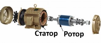
The design of an asynchronous motor is perhaps the simplest among its analogues. It consists of a rotor and a stator. Often, a three-phase winding is located on the stator, with the exception of motors designed to operate in a single-phase network with a two-phase winding or with a working and starting winding. The stator consists of a metal body and a core with windings (actually they are called the stator winding).
Since the motor is powered by alternating current, a problem arises associated with losses due to stray currents (so-called Foucault currents), for this the stator core is made of thin plates. To prevent contact with each other, steel plates are insulated with scale and secured with varnish. The current flowing in the stator windings is called stator current.
The stator housing is closed on both sides with bearing shields; sliding or rolling bearings are respectively installed in them, depending on the power and size of the machine. The bearings are covered with caps, this is necessary for their lubrication; usually they use grease such as lithol, grease and the like.
Less commonly, large and powerful electrical machines may use journal bearings with a circulating lubrication system (liquid lubrication). An oil pump pumps oil into them; in operating mode, the rotor of such machines slides over a thin oil film, similar to what happens in liners on internal combustion engines.
Based on the design of the housing and the type of fastening, motors are distinguished between lamp-mounted or flange-mounted; they also come with a combined type of fastening - with paws and a flange.
Depending on the type of engine, the shaft can come out of it from one or both sides. An actuator is attached to it; for this purpose, the end is made of a conical or cylindrical shape or with a groove for installing a key and connecting to the actuator.
Most electric motors use forced air cooling. To do this, ribs are placed longitudinally on the housing, and a cooling fan impeller is installed at the other end of the shaft. While the engine is running, it rotates and pushes air along the ribs, taking heat from the stator.
Squirrel cage and wound rotor
There are two types of asynchronous motors - with a squirrel cage and with a wound rotor.
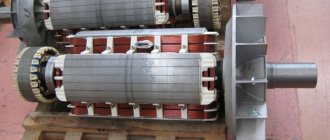
A squirrel-cage rotor or “Squirrel Cage” type rotor is a set of copper or aluminum rods (2) connected (closed) to each other by a ring (3). The rods are soldered or poured into the core (1). It is called a squirrel cage because of its external similarity, which you can see on the left side of the following illustration.
The phase rotor has a different design; a full-fledged three-phase winding is located on it; often its coils are connected in a “star” configuration, that is, their ends are connected at one point, and the beginnings of the coils are connected to conductive rings. Using the brush assembly, sliding contact with the rings is formed. It, in turn, consists of brushes and brush holders.
A wound rotor is used for soft starting or adjusting the torque on the shaft by changing the amount of motor slip by changing the active resistance of the rotor winding. To do this, an adjusting rheostat or a set of powerful resistors (for stepwise adjustment) is connected to the terminals of the brushes. In short, in a wound-rotor motor, current is not supplied to the rotor windings, as in a synchronous motor, for example, but, on the contrary, resistances are connected to them as a load.
Types of asynchronous machines
Homemade generator
Different types of AG may differ in the following performance characteristics:
- The type of rotating part of the generating device - its rotor;
- The number of output or stator windings in the generator (the number of operating phases);
- The connection diagram of the three-phase generator coils - triangle or star, as well as the method of their placement and laying on the stator poles (photo below);
We advise you to study First Aid for Electric Shock
The presence or absence of a separate excitation winding.
In accordance with the first of these characteristics, all known types of AG are equipped with a squirrel-cage or phase-wound rotor. The first of them is made in the form of a one-piece cylindrical structure, consisting of individual pins with two rings closing them (of the “squirrel wheel” type).
The phase rotor, unlike its squirrel-cage counterpart, has an inductive winding made of insulated wire, which ensures the creation of a dynamic electromagnetic field. Due to the peculiarities of its design, such a rotor has a high manufacturing cost and requires specialized maintenance.
The output windings of the stator, like the entire generator, can be single-phase or three-phase, which is determined by the direct purpose of this unit (when a voltage source of 220 or 380 Volts is required). Regarding the first of these designs, everything is quite clear, but the three-phase modification of the AG has one more feature regarding the electrical circuit for switching on the windings.
It is known that to form any three-phase power supply network in electrical engineering, two types of connection of windings are used, shifted in vector representation one relative to the other by 120 degrees. This:
Star switching, when the beginnings of the coils are connected at one point, where a zero wire is formed, and their ends diverge along three power lines (together with the neutral wire, there are four of them, as shown in the photo below);
A “triangle” connection, in which the end of one coil is connected to the beginning of the second, and so on until the chain is completely closed. The second connection option is used in 3-wire power supply lines, since there is no neutral wire in this circuit.
In each AG product, the connection according to one scheme or another is implemented in very specific ways, allowing the wires of all stator windings to be placed between the poles of its core. They are wound in such a way that each section of phase coils A, B and C is offset along the circumference from each other by exactly 120 degrees.
In conclusion of the review of generator devices, let us pay attention to the possibility of manufacturing an AG from an asynchronous motor. Such a prospect appears thanks to the well-known principle of reversibility of the action of electrical machines, according to which the direction of energy conversion can be chosen arbitrarily
Stator winding connection diagram
Since there are three windings in the stator of a single-speed asynchronous motor, to connect to a three-phase network they must be somehow connected. As in any three-phase circuit, two connection schemes are distinguished:
1. "Star". The ends of the windings are connected together, and voltage is applied to their beginnings.
2. "Triangle". The beginning of the next winding is connected to the end of the previous one.
The ends of the windings are led out into a terminal box, which is also called “brno” or “borno” (I couldn’t find the correct name, but both options are listed in the dictionary). Depending on the type and design of the engine, 3 or 6 wires can be routed into the boron. If there are 3 wires, then the windings are connected “from the factory” according to a certain circuit, and if there are 6, then you can choose the connection pattern based on the supply voltage.
Depending on the year of production and the manufacturer of the electric motor, the winding terminal designations may be used as shown in the table below.
The ends of the windings on the terminal block are located in such a way that with the help of one set of three jumpers it is possible to connect the windings according to the desired circuit. For a star connection, jumpers are installed in a row at the ends of the windings, and for a triangle, they are installed parallel to each other by connecting the “upper” and “lower” terminals. To do this, the beginnings and ends of the windings are offset from each other, as you will see in the next illustration.
The procedure for modifying the windings
Before making a generator from an asynchronous motor, you should understand its stator coils, connected to each other and connected to the supply line according to a certain circuit.
Additional Information. For the classic connection of asynchronous mechanisms, two types of connection of stator windings are used: according to the so-called “star” or “delta” circuit.
In the first case, all three linear coils (A, B and C) on one side are combined into a common neutral wire, while their other ends are connected to three phase lines. When turned on with a “triangle”, the end of one coil is connected to the beginning of the second, and its end, in turn, is connected to the beginning of the third winding, and so on until the chain is closed.
As a result of this connection, a regular geometric figure is formed, the vertices of which correspond to the three phase wires, and the neutral wire is completely absent.
For reasons of ease of installation and operational safety, in household circuits a star connection is usually chosen, which provides the possibility of organizing local (repeated) protective grounding.
When modifying the engine, you should remove the cover of the junction box and gain access to the terminals, which under normal conditions receive three-phase supply voltage. In generator mode, the supply line with household three-phase consumers connected to it should be connected to these contacts.
To organize single-phase power supply (socket lines and lighting circuits, in particular), they will need to be connected at one end to the selected phase contact A, B or C, and at the other end to the common neutral wire. The procedure for connecting wires to an asynchronous motor is shown in the following figure.
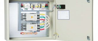
Wiring diagram on the distribution box
Important! In the case of several linear (single-phase) loads, it is necessary to distribute them among the phases so that they are loaded more or less evenly. Thus, a do-it-yourself generator assembled from a three-phase motor will be loaded on all supply circuits, and end consumers will receive the standard power they are entitled to.
Thus, a do-it-yourself generator assembled from a three-phase motor will be loaded on all supply circuits, and end consumers will receive the standard power they are entitled to.
Voltage and connection diagram
As noted above, the winding connection diagram is selected based on the available line voltage in the three-phase network. The most common voltage in the Russian Federation is 380/220. Let's say we have an engine whose nameplate looks like the one shown in the photo:
Here we see the designation “delta/star” and voltage “220/380V” - this means that if the linear voltage in the network is 380, use “star”, as is often done. But if the linear voltage in a three-phase network is 220V, then you need to connect this motor according to the “delta” circuit (this still happens today in old enterprises or individual sections of the electrical network with voltages of 220/127 volts).
Also, pay attention to these numbers when the motor is connected to a single-phase network, be it through a phase-shifting capacitor, or through a frequency converter with a single-phase input and three-phase output; always choose the winding circuit that is designed for connection to a 220V network.
Sometimes you come across old electric motors in which the windings are designed for rated voltages of 127/220 and they are not intended for direct connection to a three-phase electrical network with a linear voltage of 380V. They can only be connected to a single-phase network through a capacitor or frequency converter, as noted above, but in this case the windings must already be connected in a star.
Enterprises often use powerful electric motors, in which, on the contrary, the “triangle” circuit is designed for power supply voltage 380V, and the star 660V (then the nameplate indicates 380/660). Such motors are often used to reduce inrush currents during startup by switching the windings from a star to a delta configuration, as this is cheaper than using a frequency converter or soft starters for the same purpose.
Pay attention to what is written on the nameplate. Incorrect connection of the engine is dangerous due to its premature death.
Generator device
This generator consists of two parts, one of which is stationary and is called the stator and is the base.
The moving part is called the rotor and it rotates inside the stator.
The stator and rotor are made of special electrical steel, which very well conducts the magnetic fluxes generated during their operation.
Asynchronous generators can be either three-phase or single-phase. This depends on the number and type of connection of windings in the stator and rotor.
The conductive part of the rotors is made of aluminum and electrical steel.
When the generator begins to rotate by an internal combustion engine located on the same platform as the generator, a traveling magnetic field is formed, which is subsequently converted into electric current.
How to make a generator with your own hands
The instructions on how to make an asynchronous generator are quite simple. To do this, it is enough to find a working asynchronous electric motor.
Having disassembled it, you need to make sure that the bearings located on the rotor are suitable and, if necessary, replace them. Next, on a lathe, the diameter of the rotor core is reduced by 2-3 mm.In addition, eight recesses are made for neodymium magnets. We glue the magnets and seal the rotor. Connect the stator winding to the generator load with wires.
Solar collectors for home heating: advantages, disadvantages, myths, truth and reviews from owners (130 photos + video)Wind power plants for home - pros, cons and review of the best modern models (105 photos)
Do-it-yourself biogas plant - step-by-step description of production, 130 photos and video description of the biogas plant
Principle of operation
The frequency and power of the resulting electric current directly depend on the rotation speed of the generator. The higher the generator rotation speed, the greater the power and voltage.
If the speed drops, then the characteristics of the electric current also decrease. Therefore, many generators are equipped with automatic regulation of these parameters so that they do not affect the quality of the energy supplied.
The disadvantages of asynchronous generators include the fact that they themselves are consumers of reactive power, and due to overload during startup, significant currents will flow in the stator winding, which can lead to winding failure. To eliminate this design defect, capacitors are used.
Possibility of control
Inverter generator or regular generator: which is better?
Another feature of a synchronous generator (as well as an asynchronous one) is that the frequency and amplitude of the EMF induced at the stator terminals significantly depends on the rotor rotation speed.
Important! As the active load connected to the generator changes, the frequency of rotation of the generator shaft also changes in proportion to it, which leads to a change in the characteristics of the EMF created in the stator. This drawback forces the installation of an electronic voltage and frequency regulator in synchronous and asynchronous devices, which ensures that these parameters are maintained at the proper level (the regulator diagram is given below)
We advise you to study the Electrical Safety Rules
This drawback forces the installation of an electronic voltage and frequency regulator in synchronous and asynchronous devices, which ensures that these parameters are maintained at the proper level (the regulator diagram is given below).
Since the asynchronous generator operates on the principle of mismatched rotation of the fields of the moving and stationary parts, it is not possible to regulate the output parameters within the system. This is explained by the impossibility of organizing instantaneous voltage feedback by supplying part of the output signal from the stator to the rotor (only external voltage stabilizers can be used in AG).
This is another difference between asynchronous units and their synchronous counterparts, which in all other characteristics are very similar to the former.
Application
Asynchronous generators are recommended to be used if high requirements are not applied to the voltage parameters, the generator operates in a poor environment (for example, increased dust), it is not possible to properly maintain the generator during operation, and also if there is a possibility of overloads and emergency operation modes.
The principle of operation of the generator is to constantly be in braking mode with a rotor that rotates ahead, but still in the same orientation as the magnetic field at the stator.
Depending on the type of winding used, the rotor can be phase or short-circuited.
The rotating magnetic field created with the help of the auxiliary winding begins to induce it on the rotor, which rotates with it.
The frequency and voltage at the output directly depends on the number of revolutions, since the magnetic field is not regulated and remains unchanged.
Types of asynchronous generators
Source
Operating modes
To understand the operating features of a car generator, it is important to understand the features of each mode:
- When starting the engine, the main consumer of electrical energy is the starter. A feature of the mode is the creation of increased load, which leads to a decrease in the voltage at the battery output. As a result, consumers draw current only from the battery. That is why in this mode the battery is discharged with the greatest activity.
- After starting the engine, the car generator switches to power source mode. From this moment on, the device provides the current necessary to power the load in the car and recharge the battery. As soon as the battery reaches the required capacity, the charging current level decreases. In this case, the generator continues to play the role of the main power source.
- After connecting a powerful load, for example, air conditioning, interior heating, etc., the rotor rotation speed slows down. In this case, the car generator is no longer able to cover the current needs of the car. Part of the load is transferred to the battery, which operates in parallel with the power source and begins to gradually discharge.
We advise you to study the Soldering Iron with your own hands
https://youtube.com/watch?v=feRhd7xg6R0
Current generator device
Greetings to everyone on our website. Today we will talk about the design of a current generator. Let's try to cover this topic as much as possible and consider the design of direct and alternating current generators.
In fact, it is not entirely correct to call this device an alternating or direct current generator, since current occurs only in a closed circuit. In general, EMF, not current, occurs in the generator windings. Current begins to flow only when any consumer is connected to the windings. However, in this article we will use established concepts.
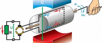
Whatever electric generators are, their main principle is the generation of electrical energy due to the rotation of the winding in a magnetic field. This means that we can distinguish two schematic types of generators: either we rotate a magnetic field in a stationary conductor, or we rotate a conductor in a stationary magnetic field.
Content:
Generator circuit from an asynchronous motor
generator circuit based on an asynchronous motor
In virtually any electric-type machine, designed as a generator, there are 2 different active windings, without which the operation of the device is impossible:
- Excitation winding , which is located on a special armature.
- Stator winding , which is responsible for the generation of electric current, this process occurs inside it.
In order to visualize and more accurately understand all the processes occurring during the operation of the generator, the best option would be to take a closer look at its operation diagram:
- Voltage supplied from a battery or any other source creates a magnetic field in the armature winding.
- The rotation of the device elements together with the magnetic field can be realized in different ways, including manually.
- A magnetic field rotating at a certain speed generates electromagnetic induction, due to which an electric current appears in the winding.
- The vast majority of circuits used today do not have the ability to provide voltage to the armature winding; this is due to the presence of a squirrel-cage rotor in the design. Therefore, regardless of the speed and time of rotation of the shaft, the power terminals of the device will still be de-energized.
When converting an engine into a generator, the independent creation of a moving magnetic field is one of the main and mandatory conditions.
Alternating current generator device
So, regarding the design of the alternator and the principle of its operation.
The most widespread are alternating current generators with a fixed conductor. This is due to the fact that the excitation current in relation to the current received from the generator is small. If you look at the picture, you will see two rings through which the excitation winding current flows and this is the weak link of any generator with an excitation winding. That is, either we supply a small excitation current through the rings through the brushes, or we remove a large operating current through the rings. In electricity, the stationary part of generators or motors that contains the winding is called the stator. The moving part may be called a rotor or armature.
DC generator device
To find out what a DC generator is, its structure and principle of operation, let’s go back a little. We have already figured out how an alternator works. Let's take a closer look at the process of EMF generation. As the rotor rotates, we have a cycle equal to one revolution of the rotor, or 360°. Let's find out what happens in this cycle:
- 0° - EMF =0
- 90° - EMF reaches its maximum value with the “+” sign
- 180° - EMF is again 0
- 270° - EMF reaches a peak value with a “-” sign
