Controlling the backup power supply by manual start is justified in many cases. However, to ensure continuous operation of electrical equipment, there is a need for uninterrupted power supply. The relevance of the issue of automation of reserve input quite often comes to the fore. For this purpose, automatic transfer switch devices (ATS) are used. Modern ATS devices for generators are reliable devices that exclude human participation in managing backup power.
Automatic control of the start of generators in the event of a network failure allows you to restore the supply of electricity almost instantly or with a slight delay. Thus, the continuous operation of electrical equipment is ensured, the stop of which may lead to undesirable consequences or provoke an emergency mode in the operation of the controlled system. Equipping diesel and gasoline generators with an electronic autostart unit is objectively a necessary measure to increase the safety of operation of individual electrical appliances.
What is AVR
This is a block consisting of several nodes, which automatically switches the load between the main and backup current sources. Some single-phase and three-phase models of gasoline and diesel generators are equipped with an automatic transfer switch initially. To switch the load, you only need to install a special switch after the electric meter. The position of the power contacts is controlled by the main power source.
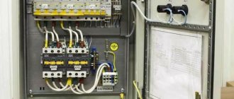
Almost all models with a battery-powered power plant can be equipped with autonomous ATS systems. In this case, ATS cabinets are used to install backup input units. In this case, ATS panels (Figure 1) can be placed directly next to gas generators or the units can be installed in a common electrical panel.
Figure 1. Example of an ATS electrical panel
The main function of the AVR unit is to automatically start the power plant after the disappearance of electric current in the general network, and then connect the load to the backup power supply. When the power supply is restored by the automation unit, the load is switched to the main electrical network, and the backup source is turned off.
Classification of ATS devices:
- by the number of reserve sections;
- voltage class;
- type of backup network (use in single-phase networks or for three-phase consumers);
- power of the served load;
- switching delay time.
The electrical circuit of the ATS can be configured in such a way as to provide energy not to the entire local network, but only to those lines that are critical. Some schemes allow you to take into account the priority of lines. First of all, power is provided to those circuits that provide electricity to important life support systems. This approach allows you to rationally distribute the load.
Main features of the ATS control unit
Automatic starting of the generator takes place only with the help of ATS. However, it does not require any human intervention. These blocks can have different configurations and types. Which device you choose depends on the model of your device. If the voltage in your network begins to drop, then the generator will automatically switch to supplying electricity. If necessary, you can make a number of adjustments to this system.
If necessary, you can even program the device for current quality. If the quality starts to drop, then the control unit will start the generator. This function is important if you connect sensitive devices to the system. The turn-on time for an additional device may vary. The speed of this process will depend on the price of your control unit. If the price is higher, then it will take him less time to start the generator. Thanks to this device, the convector in the house will work constantly.
In a private home, the speed of automatic generator start is not the main feature. It is necessary to speed up the startup process in enterprises where there is a continuous production process. If the absence of light is prolonged, then equipment failure may occur. There are control units that can switch on in a few fractions of seconds. If you live in a private house, then the generator will automatically start within 10 seconds. This period of time is optimal.
The (ATS) unit is capable of not only turning on the device. If the power supply is restored, then the device will also turn off. There are also cheap units that do not have this feature. They are inconvenient because if the electricity is restored, then the system will continue to operate. Those power plants that are equipped with this system can easily generate electricity of any power. They will not reduce the quality of the current and therefore they are used in the private sector. These devices are also used in the medical industry.
Design and principle of operation
The ATS for the generator consists of three interconnected main blocks:
- families of contactors that switch input and load circuits;
- logical and indicating devices;
- block of relay switches designed to control the generator.
In order to increase the reliability of the backup power system, ATS devices can be equipped with additional units. For example, including inverters in a circuit allows you to level out voltage dips, eliminate time delays, and improve the output current.
The switching on of the backup line is ensured by the contact group. The presence of input voltage is monitored by a phase control relay.
Let's consider the principle of operation of the backup power system using the example of a simplified diagram (Fig. 2). In normal mode, when power is supplied from the main network, the contactor unit directs electricity to consumer lines. The diagram shows an additional unit - an inverter, which converts direct current from the battery into alternating current with a voltage of 220 V.
Rice. 2. Simplified backup power circuit
The signal about the presence of input voltage is sent to the block of logical and indicating devices. In nominal mode, the entire system is in a stable state. In the event of an accident in the main network (the voltage drops below the set level), the saturation of the phase control relay solenoid becomes insufficient to maintain the contacts in the operating (normally closed) state. The contacts are disconnected and the load is disconnected from the power line.
If the system is equipped with an inverter, as shown in the diagram, it switches to the mode of generating alternating current with a voltage of 220 V. Thus, consumers receive a stable voltage even in the complete absence of current in the commercial network.
If the parameters of the power lines are not restored within a specified period of time, the controller sends a signal to start the generator. When a stable voltage is received from the alternator, the contactors switch to the backup line.
Automatic switching on of the consumer network occurs as follows: the phase control relay receives voltage, switching the contactors to the main line. The backup power circuit is disconnected. The signal from the controller is sent to the fuel supply control mechanism, which closes the valve in a gasoline engine or shuts off diesel fuel in the diesel power system. The power plant shuts down.
With full automatic switching, operator intervention is not required. The system is reliably protected from the interaction of counter currents and short circuits. For this, additional relays and interlocking mechanisms are used, which are not shown in the diagram.
If necessary, the operator can switch lines manually from the controller panel. It can also change the settings of the control unit, enable manual or automatic operating mode. A photo of the panel is shown in Fig. 3.
Rice. 3. Backup power controller panel
Several operating modes can be implemented in the ATS:
- manual;
- auto;
- semi-automatic.
The manual mode is most often used by service technicians when setting up ATS.
Advantages
This block describes the main advantages that differ from third-party manufacturers and relate directly to the automation units themselves, their technical and operational components.
| Starts at any ambient temperature. More than 60% of manufacturers use a drive from the car's central locking device as an actuator. Retail cost 100 -120 rubles. The drive has limited travel and only 2 positions. Startup is unstable, especially during cold periods. RUENERGY equipment uses an actuator of its own design. Control unit + servo drive. Starting at any temperature is achieved by precisely adjusting the choke position. With each adaptation, three damper positions are calibrated. Programming is carried out if necessary. Calibration and programming are done manually, without using a computer. |
| Versatility. Thanks to the ability to precisely adjust the position of the air damper, RUENERGY ATS units can be used on any generator model with an electric starter. Only the set of mounts changes for different types of engines. That's why we have such a wide range of electric generators with autostart. The basis is well-known, proven manufacturers: Honda, Robin-Subaru, Briggs and Stratton, Kohler. The operating algorithm of the carburetor air damper drive allows the electric generator to be started equally well both in “cold” and “hot” conditions. The thermal diode built into the board regulates the opening time of the air damper depending on the ambient temperature. |
| High-quality components and bench testing. Many manufacturers save on components, relying on a one-year warranty and use Chinese modular contactors, IEK, Metasol, etc. However, as experience shows, the Chinese save on everything, including the cross-section of conductive parts, as a result of which the starters begin to heat up. RUENERGY uses components from proven and proven manufacturers - Schneider Electric, ABB. All switchboard equipment undergoes bench testing, along with the generator. Tests are carried out under load in the main areas: voltage drop or phase loss, testing by the actuator of algorithms for starting the generator set. |
| Replacement panels for the Expert line. In the Expert line, all panels are interchangeable, from the simplest and most intuitive DKG 105 to the professional D-200 with the ability to remotely monitor and control. It is enough to replace the panel and you will get new features and functionality. The delivery set contains all the necessary diagrams: connection diagrams for all network configuration options, as well as a circuit diagram. Accordingly, in the switchboard itself, all inputs and outputs are marked according to the diagrams. The connection can be carried out by a specialist with experience and appropriate approval for electrical safety; an operating manual is provided for the user. You can download it in the product card of a specific model. |
| Remote control and GSM module. Autostart units of the “Expert” and “Pro” lines with the D-200 controller support remote monitoring and control of all available parameters from incoming voltage to harmonics in the network. The module is capable of notifying about any changes in network operation via SMS or E-mail. Control from a mobile phone is carried out via an application (Android) or browser. Control from a computer is carried out via a browser or the Scada Rainbow program via the RS-485 protocol. The GSM module works via a SIM card via GPRS. The controller has a GPS module that performs positioning on the ground. The controller has an LCD display and can be installed outdoors at temperatures down to -40 degrees Celsius (equipped with a heater). |
ATS connection diagrams and their descriptions
The main function of the ATS is to automatically switch inputs, and in such a way as to eliminate counter currents.
A simple diagram in Fig. 4 explains the switching principle.
Figure 4. ATS diagram
Contacts KM1 and KM2 are interconnected. After one contact opens, the other closes. They cannot be turned on at the same time.
There are many different schemes for connecting automatic transfer input, but the principle of their construction is always the following: ATS is installed between the input and consumers. Usually after the electric meter. The automatic switchboard itself can be located anywhere, but the principle of its connection is exactly the same. This principle is clearly illustrated by the diagram in Fig. 5.
Rice. 5. Visual diagram of connecting the ATS
A detailed connection diagram for the automatic generator start unit is shown in Figure 6. In the diagram, K1 and K2 are contactors. Numbers in circles indicate terminal numbers. Using this diagram, it is not difficult to connect such a unit yourself.
Rice. 6. Detailed connection diagram for the generator autostart unit (BAG)
A schematic diagram of connecting an ATS for a private house is shown in Fig. 7.
Rice. 7. Schematic diagram
This circuit uses an ASU that provides stable voltage and continuous power supply to the local network.
As an example, we present two circuits for three-phase current (Fig. 8). Image B shows a single-sided version (additional PH voltage relay). With this connection, the generator starts automatically after a power outage. In other words, the input from the generator is a backup.
In image A - double-sided design. Both sections have the same priority. This connection allows you to switch lines, regardless of the presence of voltage in each of them.
Rice. 8. Connection of ATS for three-phase current
The choice of scheme depends on the task that you intend to solve.
ATS for a generator, what is it?
ATS for a generator - automatic input of a reserve for a generator, designed to automatically connect an electricity consumer to the generator in the event of a failure of the main input with the ability to issue the necessary commands to automatically start the generator.
ATS for a generator (ATS - Automatic Transfer Switch) comes in three types:
- ATS with generator autostart controllers
- ATS with autostart based on relay logic
- Semi-automatic avr for generator
- ATS for generators with autostart
Self-production of AVR
If you purchased a generator with an electric starter, you can automate the process of introducing the reserve yourself. To do this, you need to choose a scheme that meets the characteristics of your home network. After that, buy all the necessary parts, taking into account the power of consumers.
You will need:
- Universal controller.
- Contactors (for the simplest circuit - at least 2).
- Electrical cabinet.
- Three-level operating mode switch.
- Power supply for 1 - 3 Amps.
- Automation for starting/stopping the generator engine (if it is not equipped with one).
- Connecting cables, working tools.
Stages of work:
- Cabinet installation. Select a suitable location for the electrical panel (preferably closer to the main input).
- Installation of parts. Place all components so that all contactors and terminals are accessible.
- Connecting lines. Strictly follow the diagrams and observe the terminal assignments. Use the markings on the covers and housings of the devices. Make sure that the wires do not cross. Lastly, connect the input wires, of course, with the input circuit breaker turned off.
- After installation, be sure to test the operation of the ATS unit.
Principle of operation
At its core, a blocking generator is an amplifier (generator) assembled on the basis of transistors arranged in one cascade. The scope is narrow: a source of impressive, but transient in time (duration from thousandths to several tens of microseconds) pulse signals with large inductive positive feedback. The duty cycle is more than 10 and can reach several tens of thousands in relative values. There is a serious sharpness of the fronts, practically no different in shape from geometrically regular rectangles.
The amplifier used to make the blocking generator is in the open position only during the formation of the pulse signal. For the rest of the time it is closed. It follows that with a large ratio of the pulse repetition period to their duration, the amplifying element is in the open position for a significantly shorter amount of time than in the closed position. The amplifier has a thermal regime. In this case, it is directly related to the average power output by the collector. Due to the high duty cycle, the devices receive significant power during low-power signal operation.
Schematic diagram for assembling a blocking generator
The significant duty cycle of the blocking oscillator allows it to operate in an economical mode, because Energy is required by the amplifier only during the open position (signal generation time). Basic operating modes: self-oscillating and standby. Let's take a closer look at them.
Self-oscillating mode
Most often, the blocking generator is assembled using amplifying elements - transistors, connected according to two main circuits:
- with a common emitter;
- with a common base.
The first is more common because, having a shorter rise time, it is possible to generate a preferred signal shape. The second circuit is less susceptible to fluctuations in amplifier characteristics.
Self-oscillating mode
The working process of the device in question is divided into 2 stages:
- the closed position of the transistor takes up the main time of the oscillation period;
- the transistor is in the open position, the signal-pulse goes through the formation stage.
Capacitor C1 is charged by the source current during the formation of the pulse. Due to this, C1 ensures the closed position of the reinforcing element. During this stage, capacitor C1 slowly discharges through the significant resistance of resistor R1. In this case, a near-zero potential is created on the basis of the VT1 diode, which does not allow it to open.
When the opening voltage threshold is reached, the opening process occurs at the amplifying element, and current will flow through winding I, called the collector winding, of transformer T. At this moment, potential induction occurs in the main or base winding II. The polarity must be such that the voltage generated at the base of the transistor has a positive polarity. If the transformer windings are connected incorrectly, the device will not generate signals. In this case, it is necessary to reconnect the ends of one of the windings. The blocking generator will start working.
Important! The dramatic development of the transistor opening process is called the direct blocking process.
A positive voltage appears in the I winding of the transformer, which leads to an increase in various currents and, consequently, a continued decrease in the voltage of the collector and base of the amplifier. There is a sharp increase in the collector current and voltage on the amplifying element. The next moment, the voltage drops to almost zero, and the device goes into saturation mode.
Important! The dramatic development of the transistor closing process is called the reverse blocking process.
The opening of the amplifier occurs almost instantly, therefore, during this entire time, the potential of capacitor C1 and the amount of energy in the transformer undergo virtually no changes. The pulse front has been formed. The peak of the pulse is formed, capacitor C1 begins to charge.
The exit of the amplifying element from the saturation mode means that the collector current again begins to depend on the amount of charge accumulated in the base of the transistor, and the base current decreases. The amplifying properties of the transistor begin to recover. At this moment, a voltage negative relative to the transistor is formed in the primary winding of the transformer. This process leads to a continued decrease in the collector current. A pulse cut is formed.
The reinforcing element is in the closed position. There is a transition to the initial state. The physical essence comes down to the dissipation of energy that appeared during the period of appearance of the signal-pulse in various reactive parts of the circuit. Since here the potential difference across the capacitor and the amount of energy in the transformer have not changed, closing the transistor provokes an increase in the voltage at the collector. At this moment, the blocking generator experiences a surge in voltage. In some cases, parasitic oscillations appear.
Ti » (3 – 5) R1С1 – this expression characterizes the self-oscillatory mode.
Waiting mode
In the standby mode of operation of the device in question, signal generation occurs only with the help of external influence - arbitrary trigger pulses must be applied to the input.
Standby mode
In the initial state, the amplifying element is closed by a negative bias on the base, and the avalanche-like development of the process of opening the transistor will begin only after applying a pulse of the opposite sign of the corresponding amplitude to the base.
The appearance of a pulse occurs in complete analogy with the self-oscillatory mode discussed above. Capacitor C1 discharges to the initial base voltage. Then the transistor remains in the closed state until the next triggering pulse appears. The duration of the signals, as well as their shape, emanating from the device in question are completely dependent on the parameters of the assembled circuit.
To ensure that the starting circuit does not have any impact on the operation of the blocking oscillator in standby mode, the presented circuit contains a special isolation diode VD2. Its task is to close immediately after the end of the opening process of the transistor. This action breaks the connection between the external source and the device of interest to us. It is allowed to add an emitter follower to the calculation of the presented circuit.
Thus, we summarize the principle of operation of a blocking generator on a field-effect transistor: if, when the voltage at the base of the transistor disappears, the conditions required to repeat the cycle without external influence are not met, then this operating mode is called standby. If, when the voltage disappears, a new cycle begins in the same place to form a new pulse without involving an external source, then the operating mode of the circuit is self-oscillating.
Selecting ATS
The table below will help you decide on the type of ATS.
Table 1
| ATS type | Device Features | Action |
| Single acting | Two sections. One working and one backup | Connects a backup line in case of power failure on the main one |
| Double acting | Sections are equivalent | You can connect any line, regardless of voltage availability |
| With restoration | Monitors the presence of voltage at the main input after switching to backup power | When voltage appears on the main line, it transfers the circuit (with a slight delay) to its original state |
| No recovery | Switches sections after voltage loss at the main input | Operator intervention is required to switch to main mode |
General principles for constructing ATS systems
Systems that switch power supply sources are designated by the abbreviation AVR - Automatic Input of Reserve. The principles of their construction are the same for both category I and category II electricity consumers.
- They must ensure complete galvanic isolation between two power sources - when one is working, all phase lines of the other are disconnected from the line supplying the consumer.
- The quality of power supply from the backup source should not be worse than from the main one. Both in terms of the number of phases and the rating of currents, voltage and power.
Providing galvanic isolation
The most common ATS circuit, which provides simple and reliable switching between power sources, is the use of magnetic starters that have two types of contacts: power and control. The first ones are always normally open - in the absence of electricity, there is no mechanical connection between the terminals. The latter can be either normally open or normally closed.
This separation allows, for example, to build a so-called blocking circuit, through which voltage is supplied to the starter retractor coil when the “Start” button is released. We will use this property to provide galvanic isolation.
For each power source, one magnetic starter is taken, the power contacts of which are designed for the standard value of current and voltage in the network of the electrical energy consumer. The input group of each is connected to its own power source - one to the power line, the other to the output of the backup alternating current generator driven by a diesel or gasoline internal combustion engine. The output groups of power contacts are combined on a phase-to-phase basis.
If the line is three-phase, then the solenoid coil of the magnetic starter - electricians call it “pull-in” - is better to have one that is designed for 380 volts and is switched on between phases. For the leading contactor (it is connected to the main line), the pull-in is switched directly between any two input phases. This solves the problem of determining the voltage in the main line. If it is absent, then the power contacts open.
The retractor of the slave contactor (the one connected to the backup line) is more difficult to connect: the first contact directly to one of the input power terminals, and the second through the normally closed additional contact of the leading magnetic starter - usually they are located on both sides of the housing, in pairs with the normally closed ones. The electrical industry also produces a block in which there are two normally closed and two normally open contacts. It is attached to a connector located on the top cover of the magnetic starter housing.
For the case when two independent (connected to different power substations) power lines are used, the circuit works like this:
- If the main line loses voltage, the pull-in coil of the lead contactor is de-energized and its power contacts open.
- At the same time, its additional contact, to which one of the terminals of the driven contactor pull-in coil is connected, closes.
- Voltage is applied to the pull-in coil of the driven contactor, it operates and closes the power contacts. The consumer is supplied with energy from a backup source.
- When voltage appears in the main line, the master contactor is activated, which causes a break in the voltage supply line to the slave solenoid coil. The backup line is turned off, and the consumer is powered from the main one.


