Since there is often a need to control a starter (contactor) from two or more places, for example, lighting in a large industrial room, control of a protractor or conveyor, a control circuit should be assembled from several push-button stations. First, let's remember the principle of operation of a magnetic starter (contactor).
A magnetic starter controls power circuits by turning on (and off) moving power contacts (located on a dielectric cross-arm) to fixed power contacts to which the power circuits are connected.
This process is controlled by an electromagnetic coil to the moving part (anchor) to which a traverse with moving contacts is attached. The coil itself is activated by applying (or turning off) the rated voltage to it (12, 24, 36, 42, 110, 220, 380 volts).
And the coil itself (through the supply and shutdown of voltage) is controlled by a push-button station consisting of two buttons:
- Start buttons (normally open contacts)
- And "Stop" buttons (normally closed contacts)
After the coil is turned on, its power is provided through closed auxiliary contacts 13/1HO - 14/1HO, which are normally open.
Now let's look at different options for connecting a magnetic starter and contactor.
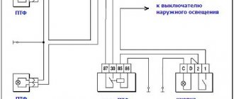
Visual connection diagram from two places
The coil must match the supplied rated voltage
Visual connection diagram from three places
As we can see from the diagram, using this principle, the number of button posts can be increased to the number we need.
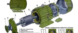
An electromagnetic starter for 380 or 220 V consists of the following elements:
- core;
- electromagnetic type coil;
- anchor;
- connecting frame;
- mechanical type sensors;
- central and auxiliary contactor system.
Additional components of the device may include electrical fuses, an additional set of terminals, a starter and a protection relay.
What is the difference between starters and contactors?
The purpose of these types of devices is almost the same, but there is still a difference. The operating principle of these devices is also the same, since their operation is based on the operating principle of an electric magnet. They are designed to operate in DC circuits with voltages up to 440V, as well as in AC circuits with voltages up to 600 V. Both have:
- Working (power) contacts to control the operation of the load.
- Auxiliary (control) contacts that ensure the functioning of signaling devices.
It would seem that there is no difference, but it is there and quite significant. Starters are produced to operate at low currents up to 10A, but contactors are designed for switching electrical circuits with high currents, which amount to hundreds of amperes. In this regard, their design may differ due to the presence of arc chambers.
The appearance is not always so different, but it happens
In addition, starters are produced in housings made of durable plastic, but contactors do not have housings (in most cases), so their installation requires protected places, such as boxes, entry into which is not possible for unauthorized persons except maintenance personnel. In addition, contactors must be protected from moisture, dust and dirt.
Starters are mainly intended for turning on/off asynchronous 3-phase electric motors. In this regard, these devices are equipped with 3 pairs of working contacts, as well as auxiliary contacts that supply power to the starter in operating mode. Such functionality is quite universal, so starters are used to control the operation of various devices located at a considerable distance.
Since their operating principle is practically the same, starters are often called “small contactors”. This can mainly be found in price lists, although previously contactors and starters were clearly distinguished. As a rule, even electricians worked more with starters.
Reversing and non-reversing starters
Devices come in various types and perform all assigned tasks.
There are two types of starters:
- irreversible;
- reversible.
In a reversing starter, there are two individual magnetic devices in one housing, electrically connected to each other and attached to a common base, but only one of these starters can function - either only the first, or only the second.
The reversible device is inserted through naturally closed blocking contacts, the role of which is to eliminate the synchronous activation of two groups of contacts - reversible and non-reversible, so that an interphase short circuit does not occur. Certain modifications of reversing starters are protected to provide the same function. It is possible to switch the power phases in turn so that the main function of the reversible starter is performed - changing the direction of rotation of the electric motor. The order of phase alternation has changed - the direction of the rotor has also changed.
Operating principle and device
It is very important to understand what the principle of operation of starters is based on, as well as how they are designed, in order to better understand the connection diagram.
The basis of the design is an electric magnet, which, in turn, consists of a moving and a fixed part. The magnetic core is distinguished by its “W”-shaped shape, while it is, as it were, cut in the middle and installed with “legs” opposite each other.
Magnetic starter device
As a rule, the lower part is stationary and securely attached to the body. The upper part is movable and mounted on springs, which automatically turn off the starter if there is no operating voltage on the coil. It should be noted that starters are available for different operating voltages, from 12 to 380 volts. The coils are easy to change, so the starters are quite repairable and the weakest link is the coil. In addition, the starter also has moving and fixed contacts, both power and control. The moving contacts are located on the moving part of the magnetic starter.
When the coil is de-energized, the moving contacts are in an open state due to the action of the spring. When the “Start” button is pressed, voltage appears on the coil. As a result, the moving part of the core is attracted, and with it the moving contacts. By connecting to the fixed contacts, an electrical circuit is formed, as a result of which operating voltage appears on the control device (electric motor): the engine starts. This can be seen in the picture below.
This is what it looks like disassembled
When the “Stop” button is pressed, the voltage on the coil disappears and the upper, moving part, due to the action of the spring, returns to its original state. The contacts open, the electrical circuit disappears, as does the voltage on the electric motor: the electric motor stops. The electromagnet is triggered by both direct and alternating voltage, the main thing is that the coil is designed for the operating voltage.
There are starters with normally closed and normally open contacts, with the latter being the most common and most in demand.
Technical characteristics and markings
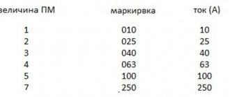
Despite the fact that the operating principle of all magnetic starters is the same, certain types of this device have a number of technical differences. To identify design features and performance characteristics, there is a system of symbols for these products. For example, you can take the specific PM marking.
PM12-025 2 4 1 UHL 2 B
PM12 – product series. All products in this series have the same housing and actuator design. The housing dimensions may vary depending on the current load. The more powerful the starting device, the larger its size.
PM12-025 _ _ _ UHL _ _ (first three digits), 025 – rated load on power contacts – up to 25 Amperes. A PM with such a current characteristic is classified as a magnetic starter of magnitude 2. PM12, depending on the size, can provide operation of electric motors, the current range of which is from 10 to 250 Amperes.
PM12 ___ 2 _ _ UHL _ _ (fourth digit), 2 irreversible starter, equipped with a thermal relay to protect the electric motor from long-term current overloads in the event of a break in one phase, as well as in the event of jamming of the drive or driving mechanism. The purpose of starters and the presence of thermal protection is determined by the following marking system:
PM12 ___ _ 5 _ UHL _ _ (fifth digit), 5 degree of protection IP20, open design, without shell. Prevents foreign mechanical objects from getting inside the device and accidental human contact with active and live parts. A magnetic starter made with this degree of protection is not protected from the ingress of water or other liquid into it, therefore, as a rule, it is placed in lockable electrical panels on DIN rails. The bulk of electrical devices that are most widely used have a degree of protection IP20.
PM12 ___ _ _ 1 UHL _ _ (sixth digit) design according to the number of block contacts, 1 – 2 normally open (open) and 2 normally closed (closed).
PM12 ___ _ _ _ UHL 2 _ (UHL) design of electrical equipment for moderately cold climates, UHL 2 - intended for operation in rooms without heating or under a canopy.
PM12 ___ _ _ _ UHL _ B (B) performance characteristics for wear resistance. A – 320 thousand cycles, B – 100 thousand cycles, C – 30 thousand cycles.
For the convenience of the average consumer, the manufacturer often, in the marking established by standardization requirements, additionally indicates the rated current characteristics of the starter, the type of current, as well as the operating voltage of the magnetic coil. Below, in highlighted text, the load characteristic is indicated - 25A, voltage - 380V and alternating current - AC.
PM12-025 2 4 1-25A-380AS-UHL2-B
Alternating current is indicated by the symbol AC, direct current by DC. The pull-in coils of PM12 starters are, in most cases, designed to operate on alternating current with a voltage of 24V, 220V or 380V.
Design and purpose of the device
Having compared the connection of the MP and the contactor, we can conclude that the first device differs from the second in that it is used to start an electric motor. You can even say that the MP is the same contactor with which an electric motor is controlled.
The difference is so arbitrary that recently many manufacturers have called MPs AC contactors, but with small dimensions. And the constant improvement of contactors has made them universal, so they have become multifunctional.
Purpose of the magnetic starter
MFs and contactors are built into power networks that transport current with alternating or direct voltage. Their action is based on electromagnetic induction.
The device is equipped with signal contacts and those through which power is supplied. The first are called auxiliary, the second - workers.
The start buttons equipped with the circuit ensure convenient operation. If you need to turn off the load, just press the “Stop” key. In this case, the supply of voltage to the starter coil will end and the circuit will break.
MPs remotely control electrical installations, including electric motors. Their role as protection is zero - only the voltage disappears or at least drops to a limit below 50%, the power contacts open.
After stopping the equipment in which the contactor is built into the circuit, it will never turn on on its own. To do this, you will have to press the “Start” key.
For safety, this is a very important point, since accidents caused by spontaneous switching on of an electrical installation are completely excluded.
Starters, the circuit of which includes thermal relays, protect the electric motor or other installation from prolonged overloads. These relays can be double-pole (TPN) or single-pole (SRP). Triggering occurs under the influence of motor overload current flowing through them.
Design and operation of the device
For the MP to operate correctly, it is necessary to adhere to certain installation rules, have an understanding of the basics of relay technology, and correctly select the equipment power supply circuit.
Since the devices are designed to operate over a short period of time, the most popular are MPs with usually open contacts. MP series PME and PAE are in greatest demand.
The first ones are built into signal circuits for electric motors with a power of 0.27 - 10 kW. The second - with a power of 4 - 75 kW. They are designed for voltage 220, 380 V.
There are four options:
- open;
- protected;
- dust and waterproof;
- dust-splashproof.
PME starters include a two-phase TRN relay in their design. In a PAE series starter, the number of built-in relays depends on the size.
The letters indicate the type of device, the numbers following them - from 1 to 6 - the value. The second number is execution. One indicates a non-reversible MP without thermal protection, two - the same, but with thermal protection, three - reversible, without thermal protection, four - with thermal protection, reversible
At about 95% of the rated voltage, the starter coil is able to provide reliable operation.
The MP consists of the following main units:
- core;
- electromagnetic coil;
- anchors;
- frame;
- mechanical work sensors;
- groups of contactors - central and additional.
The design may also include, as additional elements, a protective relay, electrical fuses, an additional set of terminals, and a starting device.
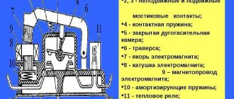
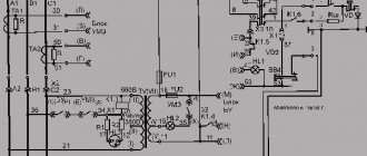
The MP includes in its design a base (1), fixed contacts (2), a spring (3), a core (4), a throttle (5), an armature (6), a spring (7), a contact bridge (8), a spring (9 ), arc chute (10), heating element (11)
Essentially, this is a relay, but it cuts off a much larger current. Since the electromagnets of this device are quite powerful, it has a high response speed.
An electromagnet in the form of a coil with a large number of turns is designed for a voltage of 24 - 660 V. Which is located on the core, more power is needed to overcome the spring force.
The latter is designed for quick disconnection of contacts, the speed of which determines the magnitude of the electric arc. The faster the opening occurs, the smaller the arc and the better condition the contacts themselves will be.
Normal state when contacts are open. At the same time, the spring holds the upper section of the magnetic circuit in a raised state.
When power is supplied to the magnetic starter, current flows through the coil and creates an electromagnetic field. It attracts the mobile part of the magnetic circuit by compressing the spring. The contacts close, power is supplied to the load, and as a result, it starts working.
If the power supply to the MP is turned off, the electromagnetic field disappears. Straightening up, the spring gives a push, and the upper part of the magnetic circuit appears at the top. As a result, the contacts diverge and power to the load is lost.
Some starter models are equipped with surge suppressors, which are used in semiconductor control systems.
You can manually check the operation of the system by pressing the armature in order to feel the force of the spring contraction. It is the contraction force that copes with the magnetic field. When the armature is fully lowered, the contacts thrown back by the spring are disconnected
After connecting the magnetic starter, the control coil is powered by alternating current, but for this device the type of current does not matter.
Starters are usually equipped with two types of contacts: power and blocking. Through the former, the load is connected, and the latter protects against incorrect actions when connecting.
There can be 3 or 4 pairs of power MPs, it all depends on the design of the device. Each pair has both mobile and fixed contacts connected to the terminals located on the body via metal plates.
The first differ in that the load is constantly supplied with power. Removal from the operating state occurs only after the starter is triggered.
Contactors with normally open contacts are supplied with power only while the starter is operating.
There are two types of blocking contacts: normally closed, normally open. The first type of contact has a “Stop” button, and the normally open one has a “Start” button.
Normally closed ones differ in that the load is constantly supplied with power, and disconnection occurs only after the starter is triggered. Contactors with normally open contacts are supplied with power only while the starter is operating.
The difference between a magnetic starter and a contactor
Often, when selecting a switching device, confusion arises between magnetic starters (MF) and contactors. These devices, despite their similarity in many characteristics, are still different concepts. A magnetic starter combines a number of devices; they are connected in one control unit.
The MP may include several contactors, plus protective devices, special attachments, and control elements. All this is enclosed in a housing that has some degree of moisture and dust protection. These devices are mainly used to control the operation of asynchronous motors.
The maximum voltage with which the magnetic starter operates depends on the electromagnetic inductor. There are MFs of small ratings - 12, 24, 110 V, but most often they are used at 220 and 380 V
A contactor is a monoblock device with a set of functions provided for by a specific design. While starters are used in quite complex circuits, contactors are mainly found in simple circuits.
220 volt coil: connection diagrams
To control the operation of the magnetic starter, only two buttons are used - the “Start” button and the “Stop” button. Their design can be different: in a single housing or in separate housings.
Buttons can be in the same housing or in different ones
Buttons produced in separate housings have only 2 contacts, and buttons produced in one housing have 2 pairs of contacts. In addition to the contacts, there may be a terminal for connecting the ground, although modern buttons are produced in protected cases that do not conduct electric current. Push-button stations in a metal case for industrial needs are also produced, which are highly impact resistant. As a rule, they are grounded.
Connection to 220 V network
Connecting a magnetic starter to a 220 V network is the simplest, so it makes sense to start familiarizing yourself with these circuits, of which there may be several.
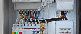
A voltage of 220 V is supplied directly to the coil of the magnetic starter, which are designated as A1 and A2, which are located in the upper part of the housing, as can be seen from the photo.
Connecting a contactor with a 220 V coil
When a regular 220 V plug with a wire is connected to these contacts, the device will start working after the plug is plugged into a 220 V socket.
Using power contacts, it is permissible to turn on/off an electrical circuit for any voltage, as long as it does not exceed the permissible parameters indicated in the product passport. For example, you can apply battery voltage (12 V) to the contacts, with which a load with an operating voltage of 12 V will be controlled.
It should be noted that it does not matter which contacts the single-phase control voltage is supplied to, in the form of “zero” and “phase”. In this case, the wires from contacts A1 and A2 can be swapped, which will not affect the operation of the entire device.
It is quite natural that such a switching circuit is used extremely rarely, since it requires direct voltage supply to the coil of the magnetic starter. In this case, there are many options for switching on, using a time relay or a twilight sensor, connecting, for example, street lighting to power contacts. The main thing is that the “phase” and “zero” are nearby.
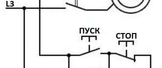
Using the Start and Stop buttons
Basically, magnetic starters are involved in the operation of electric motors. Without the presence of the “Start” and “Stop” buttons, such work is associated with a number of difficulties. This is primarily due to the operating characteristics of electric motors, which are often located at a considerable distance. The buttons are connected to the coil circuit in series, as in the figure below.
Switching diagram of a magnetic starter with buttons
This method is characterized by the fact that the magnetic starter will be in working condition as long as the “Start” button is pressed, which is very inconvenient. In this regard, the circuit includes additional (BC) contacts of the magnetic starter, which duplicate the operation of the “Start” button. When the magnetic starter is turned on, they close, so after releasing the “Start” button, the circuit remains operational. They are designated in the diagram as NO (13) and NO (14).
Connection diagram for a magnetic starter with a 220 V coil and a self-retaining circuit
You can turn off running equipment only using the “Stop” button, which breaks the electrical power supply circuit of the magnetic starter and the entire circuit. If the circuit provides other protection, for example, thermal, then if it is triggered, the circuit will also be inoperable.
Power for the motor is taken from the T contacts, and power is supplied to the magnetic starter contacts, designated L.
This video explains in detail and shows in what order all the wires are connected. In this example, a button (button post) is used, made in one housing. As a load, you can connect a measuring device, an ordinary incandescent lamp, a household appliance, etc., operating from a 220 V network.
How to connect a magnetic starter. Connection diagram.
Magnetic starter control circuit from two and three places
Hello, dear readers and guests of the Electrician's Notes website.
After publishing an article about a magnetic starter connection diagram, I very often began to receive questions about how to control a motor from two or three places.
And it’s not surprising, because such a need can arise quite often, for example, when controlling an engine from two different rooms or in one large room, but from opposite sides or at different height levels, etc.
So I decided to write a separate article about this, so that those who come back with a similar question will not have to explain every time what needs to be connected where, but simply give a link to this article, where everything is explained in detail.
So, we have a three-phase electric motor controlled through a contactor using one push-button post. I explained in great detail how to assemble such a circuit in an article about the magnetic starter connection diagram - follow the link and get acquainted.
Here is a diagram for connecting a magnetic starter through one push-button post for the example above:
Here is a mounting version of this circuit.
Be careful! If your linear (phase-to-phase) voltage of a three-phase circuit is not 220 (V), as in my example, but 380 (V), then the circuit will look similar, only the starter coil must be at 380 (V), otherwise it will burn out.
Also, control circuits can be connected not from two phases, but from one, i.e. use any one phase and zero. In this case, the contactor coil should be rated 220 (V).
Engine control scheme from two places
I slightly modified the previous diagram by installing separate circuit breakers for the power and control circuits.
For my example with a low-power engine, this was not a critical mistake, but if you have an engine of much higher power, then this option will not be rational and in some cases not even feasible, because the cross-section of the wires for the control circuits in this case should be equal to the cross-section of the wires of the power circuits.
Let's assume that the power and control circuits are connected to one circuit breaker with a rated current of 32 (A). In this case, they must be of the same cross-section, i.e. not less than 6 sq. mm for copper. What is the point of using such a cross-section for control circuits?! The consumption currents there are quite negligible (coil, signal lamps, etc.).
What if the engine is protected by a circuit breaker with a rated current of 100 (A)? Imagine then what wire cross-sections will need to be used for control circuits. Yes, they simply simply will not fit under the terminals of coils, buttons, lamps and other low-voltage automation devices.
Therefore, it would be much more correct to install a separate machine for control circuits, for example, 10 (A) and use wires with a cross-section of at least 1.5 sq. mm for the installation of control circuits.
Now we need to add another push-button control station to this circuit. I’ll take as an example a PKE 212-2U3 post with two buttons.
As you can see, in this post all the buttons are black. I still recommend using button posts for control, in which one of the buttons is highlighted in red. It should be given the designation “Stop”. Here is an example of the same post PKE 212-2U3, only with red and black buttons. Agree that it looks much clearer.
Turning on/off a 380 V asynchronous motor
Despite the fact that the motor is 3-phase (380V), a 220 V coil is used. The difference between this circuit is that the power contacts switch 3 phases (380 V), and the magnetic starter is controlled using 1 phase (220 V ). Phases A, B, C are connected to contacts L1, L2, L3, and the electric motor is connected to contacts T1, T2, T3. The control voltage is supplied to contacts A1 and A2, and one of these contacts is supplied with one of the phases, for example phase B, although any phases can be connected. The second contact is connected to the neutral wire. A block contact (BC) is also connected, ensuring the operation of the equipment after the “Start” button is released.
Connecting a three-phase motor via a starter
The circuit has been slightly modified due to the addition of a thermal relay that protects the electric motor from overloads, as well as a QF circuit breaker that protects the circuit from short circuits.
The connection procedure is presented in the following video.
How to connect a three-phase motor through a magnetic starter.
Starting the motor in reverse
For individual equipment to function, it is necessary that the motor can rotate both left and right.
The connection diagram for this option contains two MPs, a push-button station or three separate keys - two starting ones “Forward”, “Back” and “Stop”.
From short circuit the power circuit is protected by normally closed contacts KM1.2, KM2.2.
The circuit is prepared for operation as follows:
- Turn on AB QF1.
- The power contacts of MP KM1, KM2 receive phases A, B, C.
- The phase that supplies the control circuit (A) through SF1 (signal circuit breaker) and the SB1 “Stop” key is supplied to contact 3 (keys SB2, SB3), contact 13NO (MP KM1, KM2).
Next, the circuit operates according to an algorithm depending on the direction of rotation of the motor.
Engine reverse control
Rotation begins when the SB2 key is activated. In this case, phase A is supplied through KM2.2 to the MP coil KM1. The starter starts turning on with the closing of the normally open contacts and the opening of the normally closed ones.
Read also: How to foam without a foam gun
The closure of KM1.1 provokes self-catching, and the closing of the KM1 contacts is followed by the supply of phases A, B, C to identical contacts of the motor windings and it begins to rotate.
The action taken will disconnect the circuit, control phase A will no longer be supplied to the KM1 inductor, and the core with contacts will be restored to its original position by means of a return spring.
The contacts will disconnect and the voltage supply to the motor M will stop. The circuit will be in standby mode.
It is launched by pressing the SB3 button. Phase A through KM1.2 will go to KM2, MP, will work and through KM2.1 will be self-retaining.
Next, the MP, through contacts KM2, will swap the phases. As a result, the motor M will change the direction of rotation. At this time, connection KM2.2, located in the circuit supplying MP KM1, will disconnect, preventing KM1 from being turned on while KM2 is operating.
Power circuit operation
The responsibility for switching phases to redirect the rotation of the motor rests with the power circuit.
When the contacts of MP KM1 are triggered, the first winding receives phase A, the second winding receives phase B, and the third receives phase C. In this case, the motor rotates to the left.
When KM2 is triggered, phases B and C are relocated. The first goes to the third winding, the second to the second. There are no changes in phase A. The engine will begin to rotate to the right.
Reversible motor switching circuit
The advantage of asynchronous 3-phase motors is that they can rotate in different directions; it is enough to swap only 2 phases. Similar circuits are used quite often, but to implement this circuit you need to have two magnetic starters, as well as an additional button. Typically, the operation of the electric motor is controlled by 3 buttons: the “Forward” button, the “Back” button and the “Stop” button.
Reversible diagram for connecting a three-phase motor through magnetic starters
In the absence of a 220 V magnetic starter and in the presence of a 380 V one, the neutral wire is not used to operate the circuit, but another phase is used.
The circuit also provides protection in case 2 starters are turned on simultaneously. The protection is implemented on the basis of normally closed contacts, while the contacts of another starter are used. When one of the starters is on, the normally closed contacts open the electrical circuit and do not allow control voltage to be supplied to the other starter. In the diagram these are contacts KM1 and KM2, connected to the circuit of coils of the corresponding starters. Therefore, it will not be possible to turn on two magnetic starters at the same time. If switched on incorrectly, when two starters can turn on at once, a short circuit results, which will immediately damage the magnetic starters, and possibly the equipment.
In fact, not all magnetic starters have a complete set of normally closed and normally open contacts. In this case, it is permissible to install an additional unit in the form of a contact attachment, although ready-made magnetic starters with similar attachments are available. They are used in complex control circuits for various equipment, and for simple circuits it is enough to have only one normally closed and one normally open additional contact.
Magnetic starter with a contact attachment installed on it
The following video demonstrates the operation of a circuit that allows you to control the operation of an electric motor in reverse mode.
Reversible connection diagram for a magnetic starter
How to connect the starter?Video
I will not go into detail about what a starter or contactor is, what they are needed for, etc.
I'll show you right away how to connect them.
Their connection circuit is exactly the same, regardless of size and purpose, since the operating principle is the same. To remotely control the contactor on/off, a PKE push-button station with red “Stop” buttons and a black “Start” button is used.
Buttons with return, that is, after they are pressed, they return to their original position on their own. There is a contact inside the button that opens or closes when pressed.
Start”, on the contrary, closes.
The logic of the contactor switching circuit is simple: when you press the “Start” button, voltage is applied to the contactor coil and it turns on, the power contacts close and remain in the on position even after the “Start” button returns to its original state.
The contactor is turned off by pressing the “Stop” button.
That is, both buttons are pressed briefly.
How does the contactor stay on after the start button is released?
After all, the switching contact seems to be open?
To do this, the contactor has a block contact or an auxiliary, non-power contact that closes or opens together with the power contacts of the contactor.
The switching circuit requires a normally open contact.
After the “Start” button is released, the control phase to the coil goes precisely through this block contact, which is closed when turned on. Contactor coils are available for different voltages - 220 or 380 Volts.
Regardless of the voltage, the connection of the coil is the same - the supply voltage is connected directly to one terminal.
The control phase to the coil goes to the second output through buttons.
I am telling you the most simplified circuit for remote control of a starter; in fact, the circuit may also contain contacts of thermal relays and other protective devices.
So, assembling the circuit:
To connect the buttons you need a three-wire cable.
The control phase is usually taken directly from the power contacts, where the input cable comes and goes to the “Stop” button.
After the “Stop” button, the control phase is connected: - with a jumper to the “Start” button - to the block contact of the contactor. After the “Start” button - to the second end of the contactor block and from here - to the contactor coil.
That is, the “Start” button and the block contact are connected in parallel to each other.
But here it is important not to mix up the wires, otherwise the contactor will not turn on.
It is necessary to remember: the control phase wire connected after the “Stop” button (between it and the “Start” button) MUST NOT be connected to the coil.
For those who have fast Internet, watch the video that I filmed just yesterday especially for you:
I believe that every electrician should know and be able to connect a starter.
Be the first to know about new site materials!
Just fill out the form:
Starter connection diagram
Switches are used to supply power to various electrical appliances. Depending on the power of the electrical installation, the contacts of the switches are designed: the higher the current (power consumption), the greater the mass and contact area of the metal. Accordingly, the clamping device (spring, steel plate) must provide greater pressing force. If the switch is manual (mechanical), its size will be too large and it will be inconvenient to use.
Such input devices have a number of disadvantages (in addition to dimensions):
- too much effort when turning on (off);
- contact groups are not designed for frequent switching: they wear out quickly;
- safety issues have not been resolved: too much time is wasted when emergency shutdown is necessary;
- “switches” must be placed near the work area (in close proximity to the electrical installation), this is not always convenient due to the same dimensions.
The only way out is to connect the motor (or other electrical appliance) through the starter.
Where and why it is used
Electromagnetic starters and contactors are built into a power network that transports current; it can be direct or alternating voltage; the work is used on electromagnetic induction. The devices are equipped with a set of signal contacts, through which the connected devices are powered. Some perform an auxiliary function, while others perform a working function.
Electrical installations and electric motors are controlled by starters, but do not protect them in the event of a voltage drop, since the power contact opens, and the operation of the device to which the electromagnet is distributed is suspended and independent activation is excluded.
To put the equipment into operation, you need to use the “start” button. This ensures safety, since accidents may occur due to spontaneous activation.
The starter connection circuits may include relays with thermal action; they are designed to protect electric motors and other installations from long-term operation. There are single-pole and double-pole magnetic starters. They are triggered when exposed to a current overload of motors through which voltage passes.