How the PME-211 magnetic starter works
To turn on a single-phase load of low power, toggle switches, buttons, switches are used, the contact system of which is mechanically driven and designed for small currents. To start and stop a three-phase load, an electrical device is required that would simultaneously supply voltage to all poles of electrical receivers, quickly disconnect from the supply network, extinguish the electric arc at high phase currents, etc. One of such devices is a magnetic starter, which is most often used for controlling asynchronous motors, electric heating units (heaters, electric boilers) and various low-power transformers, lighting networks and other electrical equipment. Let's look at how the magnetic starter of the PME-211 series is designed, activated and connected to the network.
Magnetic starter device
In addition to mechanical action, power contacts can be closed and opened using an electric drive. A fairly simple and common device is an electromagnet. Its most important ability is to attract metal objects when an electric current flows through its coil with a core, and to release it in the absence of current. Thus, an electromagnet has the ability to convert electrical energy into mechanical energy. If you combine a coil with a core, a movable attracting part with a return spring and power contacts in one housing, you will get a ready-made switching device. All electromagnetic relays, contactors and starters operate on this principle. Although their operating principle is the same, they are structurally different.
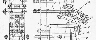
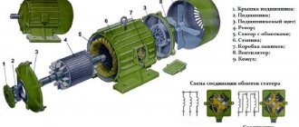
The collapsible body consists of three parts. The upper part of the cover closes the power contacts and extinguishes the electric arc during switching. Made from press material containing asbestos. In addition, the technical characteristics of the starter are indicated on the cover, such as series, rated voltage of the retractor coil, designation of power contact terminals, etc.
Fixed power and blocking contacts are fixed on the middle part, as well as movable ones on the traverse with an anchor.
And the third, the base, in which the retractor coil with the core is located. The collapsible body is cast from carbolite - phenol-formaldehyde resin with various mineral and organic fillers. This type of dielectric has high heat resistance and is difficult to ignite.
Let's take a closer look at all the elements of the PME-211 magnetic starter.
Magnetic core. The core and armature are made in the form of an W-shaped disconnected magnetic circuit. Like any other magnetic system for alternating current, it consists of sheets of electrical steel, insulated from each other to reduce eddy currents. To avoid shocks when turned on and strong vibrations during operation of the PME-211 magnetic starter, the contact points between the armature and the core are polished and smooth, and short-circuited turns made of non-magnetic material are additionally installed on the outer rods.
Power and blocking contacts are made in the form of rectangular plates of various shapes and thicknesses made of brass with soldering made of technical silver. The use of alloys with this precious metal is due to their resistance to electric arcs and mechanical shocks when turning the magnetic starter on and off. The content of technical silver in PME-211 is 10-11 grams.
on the retractor coils , and on magnetic starters of various brands the brand, wire diameter and number of turns are also written. The higher the voltage the coil is designed for, the higher the number of turns and the active resistance of its wire. If a voltage is applied to the coil above or below its rated value (380 V instead of 220 V and vice versa), this will lead to abnormal operation of the magnetic starter (loud crackling noise when the armature and core interact, failure of the magnetic starter to operate, etc.) and the coil will exit building.
In no case should the rated voltage be applied to the pull-in coil separately from the magnetic circuit, since in this case the magnetic flux will be closed on the turns of the coil, which will increase the current flowing through it and the coil will “burn out”.
A magnetic starter works on the following principle . When an alternating voltage is applied to the coil, an alternating electric current begins to flow in it, which, in turn, creates a magnetic flux in the core and armature, overcoming the resistance of the air gap. As a result, the magnetized armature is attracted to the core, closing the power and blocking contacts of the starter!
Technical characteristics of the magnetic starter PME-211-UHL4V
The main technical characteristics of the starter are given on the starter plate or on the top cover.
- alternating voltage of magnetic starter coil: 220 V, 380 V;
- rated voltage and current of the power circuit: at 380 V - 25 A, at 660 V - 14 A;
- rated power of the connected electric motor: no more than 11 kW;
- climatic modification UHL4 and wear resistance category B;
- fastening the case with screws;
- 2 normally open and 2 normally closed blocking contacts are installed.
Magnetic starter and magnetic contactor
The difference between a magnetic starter and a magnetic contactor is how much load power these devices can switch.
The magnetic starter can be “1”, “2”, “3”, “4” or “5” magnitude. For example, the second magnitude starter PME-211 looks like this:
The names of the starters are deciphered as follows:
- The first sign P is the Starter;
- The second sign M is Magnetic;
- The third character E, L, U, A... is the type or series of the starter;
- The fourth digital digit is the starter size;
- The fifth and subsequent digital characters are the characteristics and types of the starter.
Some characteristics of magnetic starters can be seen in the table
The differences between a magnetic contactor and a starter are very conditional. The contactor performs the same role as the starter. The contactor makes similar connections as the starter, only the electrical consumers have greater power, and accordingly the dimensions of the contactor are much larger, and the contacts of the contactor are much more powerful. The magnetic contactor has a slightly different appearance:
The dimensions of contactors depend on its power. The contacts of the switching device must be divided into power and control. Starters and contactors must be used when simple switching devices cannot control large currents. Due to this, the magnetic starter can be placed in power cabinets next to the power device that it connects, and all its control elements in the form of buttons and push-button switching stations can be located in the user’s work areas. In the diagram, the starter and contactor are indicated by the following schematic sign:
where A1-A2 is the starter electromagnet coil;
L1-T1 L2-T2 L3-T3 power contacts to which the three-phase power voltage (L1-L2-L3) and the load (T1-T2-T3) are connected, in our case an electric motor;
13-14 contacts blocking the engine control start button.
These devices can have solenoid coils for voltages of 12 V, 24 V, 36 V, 127 V, 220 V, 380 V. When an increased level of safety is required, it is possible to use an electromagnetic starter with a 12 or 24 V coil, and the load circuit voltage can have 220 or 380 V. It is important to know that connected starters for connecting a three-phase motor can provide additional safety in case of accidental loss of voltage in the networks. This is due to the fact that when the current in the network disappears, the voltage on the starter coil disappears and the power contacts open. And when the voltage returns, there will be no voltage in the electrical equipment until the “Start” button is activated. There are several circuits for connecting a magnetic starter.
PME-211 magnetic starter device
The main design element of the PME211 starter is the retractor coil. It is wound with copper wire in enamel insulation. Now its frame is made of plastic. During Soviet times, carbolite was used.
The coil is installed on a stationary W-shaped magnetic circuit. Its already movable part is adjacent to it on top. When voltage is applied to the coil, these two halves are attracted to each other, powering the entire mechanism. In the event of a power failure, the spring again tilts the moving part of the magnetic circuit back to its original state. This movement is transmitted through a mechanical connection to the power and auxiliary contacts of the device.
When triggered, the starter emits a click characteristic of such devices. At this moment, the state of its contacts switches. Those of them that are open at rest are closed. Depending on the modification, another type of contact is possible. Initially, they are in a closed state, but when the PME211 starter is triggered, they open.
Additional Information. You can use an ohmmeter to check the integrity of the control coil wire. If it is not available, a multimeter in diode testing mode will do. A working one will always have some resistance. It ranges from tens to thousands of ohms and depends on the parameters of the winding wire.
Magnetic starter
The magnetic starter PME-211 consists of a collapsible housing, an electromagnet, contacts, both power and auxiliary (locking). In the lower part of the carbolite body there is a core with a retractor coil. At the top there are power contacts, which are connected to the movable core and when the coil is triggered, they are retracted, thereby closing the power contacts. The PME-211 magnetic starter also has auxiliary contacts, or, as they are also called, blocking contacts. When the power ones close, they block power to the contactor coil. This eliminates the need to constantly press the start button.
The magnetic starter has a protective cover on top that covers the power contacts. The core consists of layers of special ferromagnetic steel, interconnected into a single shape.
Magnetic starter size
For the correct and long-term operation of PME211, it is important that its characteristics (capabilities) correspond to the parameters of the electrical installation in which it is to be used.
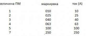
The most important of these criteria is the maximum permissible current. For convenience, all starters are divided into 8 values according to load capacity. They are numbered from 0 to 7. Zero-value starters are capable of switching currents up to 6.3 amperes (A). These devices are mostly used in relay protection and automation circuits. 1st size starters are already more powerful. They are capable of controlling currents up to 10 A. The remaining ratios are as follows:
- 0 – 6.3A;
- 1 – 10 A;
- 2 – 25 A;
- 3 – 40 A;
- 4 – 63 A;
- 5 – 100 A;
- 6 – 160 A;
- 7 – 250 A.
Characteristics of the magnetic starter PME-211-UHL4V
The most important performance characteristics of the PME211-UHL4V magnetic starter are printed on its body. More detailed information is encrypted in its full marking. If the tag is unreadable for some reason, then all parameters can be found in the passport and instructions.
The PME 211 magnetic starter is equipped with control coils for voltages: 24, 36, 40, 42, 48, 110, 127, 220, 230, 240, 380, 400, 415, 440, 500 and 660 V at a current frequency of 50 Hz. At a voltage at the power terminals of 380 V, their maximum switching current does not exceed 25 A, at 660 V - 14 A. These characteristics allow the use of PME211 to switch on consumers with a power of up to 11 kW.
The “UHL” design indicates that the magnetic starter is suitable for operation in moderate and cold climates. The number “4” means that it is used in indoor heated rooms with ventilation and low dust content in the air. “B” – low wear resistance class.
380 V starter
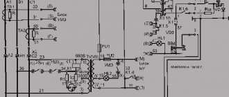
380V starters are also common, but are more often found in industrial, high-power installations with power from all three phases. The scheme for their inclusion is no more complicated. The difference from connecting to 220 V is that when powered by 380, two opposite phases are supplied to the control coil.
When the “START” button is turned on, the voltage of phases L2 and L3 rushes to the retractor coil of the KM magnetic starter. The latter works. The power contacts of the starter close and the engine starts. At the same time, the normally open blocking contacts K (pickup) are switched on. Next, the current will flow through them, maintaining the starter in the on state, regardless of whether the “START” button is closed. To turn off the engine, just break the control circuit with the “STOP” button. After this, the circuit will return to its original state.
380 V starter connection diagram
Options for connecting starters for 220 and 380 volts
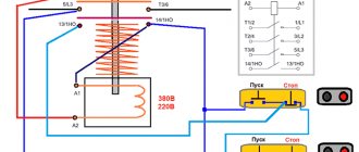
How to connect a magnetic starter to a 220 volt network (Fig. 1). The starter will operate as follows. The flow of current to the KM 1 coil is observed through a thermal relay and terminals combined into a common push-button circuit SB 2 and SB 1. They correspond to the START and STOP actions, performing an on and off function.
By pressing the START button, the movement of electric current inside the coil begins. At the same time, the starter core acts on the armature and attracts it towards itself. Ultimately, the moving contacts close, and the 220V mains voltage goes to the load. After returning the START button, it becomes released, and the circuit continues to remain closed due to the fact that a block contact KM 1, equipped with closed contacts, is installed in parallel with it.
By pressing the STOP button, a short period of no voltage begins and the position of the moving contacts returns to its original form. The same principle applies to the thermal relay P, which breaks the neutral wire N connected to the coil.
Connecting the trigger mechanism to a 380-volt power supply (Fig. 2) is generally similar to the previous option. Here there will only be a different form of applied voltage going into the coil. To supply it, two phases L1 and L2 are used, and for the first 220 V option it was phase L3 and zero. The connection of phase L1 with the coil is carried out directly, and with the second phase L2 - through the existing buttons, as well as through switching of a thermal relay. All involved buttons are connected using a daisy chain circuit.
Read also: Tool alloy steels marking
This 380 V magnetic starter connection circuit works as follows. After the START button is pressed and the thermal relay button is turned on, the voltage in phase L2 approaches the starter coil. The retraction of the core begins and the closure of the contact group, which provides for work with a specific unit. As a result, a current of 380V begins to move in the circuit.
Features of connecting PME-211 starters
Any contactor or magnetic starter, incl. PME211 should be used based on the characteristics for which it is designed. The main ones include control voltage and current. However, the requirements do not end there.
The operating conditions of the magnetic starter must meet the requirements of the “Rules for the technical operation of electrical installations by consumers.” Even the altitude above sea level is regulated. In normal mode, it should not exceed 2,000 m. At altitudes from 2 to 4.3 km, the operating current should be limited by 10%. In this case, the PME211 magnetic starter is mounted on a vertical surface with a maximum deviation from this position of no more than 90°. Its contact connectors must be clean and have a characteristic metallic sheen.
At the moment the magnetic starter is triggered, a mechanical impulse passes through its entire volume. This is caused by the “impact” of its contacts and the halves of the magnetic circuit. Therefore, such a device is subject to vibration. For this reason, it is advisable to connect flexible mounting wires in soft insulation to the magnetic starter. Rigid monolithic ones break off relatively quickly. The situation is further complicated by the fact that the location of such a break is usually hidden under insulation and is not visible visually.
How to connect a push-button post
The push-button station plays a leading role in the process of performing control functions in relation to the magnetic starter. In this regard, its design and operating principle should be considered in more detail. The presented diagram includes additional buttons. By clicking on them, you can alternately turn on and stop the engine.
The connection diagram of the STOP button to the control chain is carried out in a serial version, and a parallel connection is provided for the START button. The entire design consists of a two-button post with start and stop functions. It includes two pairs of contact groups consisting of normally closed and normally open contacts.
Voltage is supplied to the buttons through terminals installed inside the power contacts of the magnetic starter. First, the current flows to the STOP button, then continues along the normally closed contact and moves along the jumper to the START button. When the START button is pressed, this causes the normally closed contact to close. Thus, the voltage reaches the desired place, which causes the coil to operate and the core to retract under the influence of the electromagnetic field. After this, the power and auxiliary contacts, circled in the diagram shown with a dotted line, come into action.
Using an auxiliary block contact allows you to bypass the contact of the start button so that when it is released, the device remains in the on state. The magnetic starter can be turned off via the STOP button, while the voltage is removed from the control coil and the springs return the contacts to their original position.
Delivery
Transport companies Business lines PEK Courier services EMS Russian Post SDEK Boxberry pick-up points (4-6 days) SDEK (2-6 days)
Discount system in the online store
The cumulative discount system starts working from the moment you make your first purchase.
The size of the discount depends on the amount of purchases over the last six months, including the current purchase:
3%
— amount of purchases for six months from 30,000 ₽
5%
— amount of purchases for six months from 60,000 ₽
7%
— amount of purchases for six months from 90,000 ₽
Discounts cannot be combined. Discounts do not apply to products in the “Decorative lamps, chandeliers and sconces” section. Discounts on certain items may be limited by manufacturers.
Identification of buyers in the online store is carried out using the link “Name + mobile phone number”; registration is not required.
In the cart, the discount is indicated for reference, since only the current purchase is taken into account. The final discounts for the discount system and promotions are entered by the manager when processing the order.
Purpose of magnetic starters PME-211
The direct and most common purpose of magnetic starters is to start powerful three-phase electric motors. Using several starters, you can get a reverse circuit. With this connection, two devices are involved in the operation. The direction of rotation of the motor will depend on which one is currently turned on. Similar assemblies are also sold ready-made. They must have a mechanical or electrical interlock. This system prevents the simultaneous activation of both starters. Otherwise, an interphase short circuit will occur, which can lead to equipment failure. Using PME 211, the reverse connection diagram is shown below.
Reverse circuit
Additional Information. The direction of rotation of an asynchronous motor depends on the phase sequence. That is, if you swap any two of them (L1 and L3 or L1 and L2), the drive will start moving in the other direction. The operation of the reverse circuit is based on this property of engines. When the 1st starter is turned on, there is one phase order, when the 2nd starter is turned on, there is another.
Another connection of starters is three-phase motor protection. It ensures the safe operation of the latter. To power an electric motor, it is necessary to have three phases, i.e. L1, L2 and L3. If one of them is missing, for example, due to a broken cable or burnt contacts of the starter, the drive windings will inevitably fail. To prevent such an emergency situation, a circuit with three magnetic starters is used. It is assembled in such a way that if any of the three phases are lost, the remaining two are automatically turned off. The engine simply stops, but remains operational.
Standard switching diagram for magnetic starters
This starter connection diagram is required in order to start the engine through the starter using the “Start” button and de-energize this engine with the “Stop” button. This is easier to understand if you divide the circuit into two parts: the power circuit and the control circuit. The power part of the circuit should be powered with a three-phase voltage of 380 V, having phases “A”, “B”, “C”. The power part consists of a three-pole circuit breaker, power contacts of the magnetic starter “1L1-2T1”, “3L2-4T2”, “5L3-6L3”, as well as an asynchronous three-phase electric motor “M”.
The control circuit is supplied with 220 volt power from phase “A” and to the neutral. The control circuit diagram includes the “Stop” button “SB1”, “Start” “SB2”, the coil “KM1” and the auxiliary contact “13HO-14HO”, which is connected in parallel with the contacts of the “Start” button. When the circuit breaker of phases “A”, “B”, “C” is turned on, the current passes to the contacts of the starter and remains on them. The supply control circuit (phase “A”) passes through the “Stop” button to contact 3 of the “Start” button, and in parallel to the auxiliary contact of the 13HO starter and remains there on the contacts. If the “Start” button is activated, voltage comes to the coil - phase “A” from the starter “KM1”. The starter electromagnet is triggered, the contacts “1L1-2T1”, “3L2-4T2”, “5L3-6L3” are closed, after which a voltage of 380 volts is supplied to the engine according to this connection diagram and the electric motor begins to operate. When the “Start” button is released, the starter coil supply current flows through contacts 13HO-14HO, the electromagnet does not release the starter power contacts, and the engine continues to operate. When the “Stop” button is pressed, the power supply circuit of the starter coil is de-energized, the electromagnet releases the power contacts, voltage is not supplied to the engine, and the engine stops.
You can also watch the video to see how to connect a three-phase motor:
220 volt network
When powered from a 220 volt single-phase network, the connection is made through the terminals, which are usually designated A1 and A2. They are located at the top of the starter housing. When a wire with a plug is connected to them, the device is connected to the network. The terminals marked L1, L2, L3 are supplied with any voltage removed from contacts T1, T2 and T3.
When connecting to a device, zero and phase can be easily transferred, this is not important. Typically, power is supplied through a temperature or light level sensor, for example, when connecting the starter to autonomous heating or street lighting.