If there is a closed circuit in which a current flows, creating a magnetic field (magnetic flux), then there is a relationship between the current and the flux. The proportionality coefficient between these quantities is the definition of inductance.
Current circuit
This proportionality can also be called a characteristic of the inertia of an electrical circuit, which is directly related to the concept of self-inductive emf, which occurs in the circuit when the current strength changes.
Designation and units of measurement
What does inductance depend on?
In honor of Lenz, the unit of inductance was designated by the symbol "L". Expressed as Henry, abbreviated as Gn (in English literature N), in honor of the famous American physicist.
Joseph Henry
If, with a current change of one ampere for every second, the self-inductive emf is 1 volt, then the inductance of the circuit will be measured in 1 henry.
How can inductance be designated in other systems:
- In the SGS system, SGSM - in centimeters. To distinguish it from the unit of length, it is designated abhenry;
- In the SGSE system - in StatHenry.
Physics of capacitive characteristics
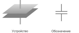
Devices that have the ability to store energy in the form of an electrical charge and thereby produce a potential difference are called capacitors. In their simplest form, they consist of two or more parallel conducting plates, spaced a short distance apart, but electrically separated either by air or some other insulating material, such as wax paper, mica, ceramic, plastic, or a special gel.
You might be interested in: Design and principle of operation of a current transformer
If you connect a voltage source to the plates, one of them will receive an excess of electrons, and the other will develop a deficiency. The ions and electrons on each of these plates are attracted to each other, but thanks to the dielectric barrier they do not connect, but accumulate on the planes of the conductors. As a result, the first plate (electrode) will be negatively charged, and the second - positively. Stationary charges create a constant electric field, theoretically maintained for an unlimited amount of time in an open electrical circuit.
The flow of electrons into the plates is called the charging current, which continues to be present until the voltage across the plates equals the applied voltage. At this moment, the capacitor is considered fully charged, that is, there are so many charges on the plates that they repel new ones. When a load is connected to a charged device, electrons and ions find a new path to each other. In this case, the capacitor acts as a current source until the potential difference across the electrodes is lost.
The ability of a capacitor to store charge Q (measured in coulombs) is called capacitance. The larger the area of the plates and the smaller the distance between them (due to the increased effect of charge attraction between the plates), the greater the capacity of the device. The degree of proximity of the plates is limited by the ability of the dielectric to resist discharge by breakdown between them. Thus, three characteristics determine the performance of a capacitor:
- plate geometry;
- the distance between them;
- dielectric material between the plates.
Properties
Has the following properties:
- Depends on the number of turns of the circuit, its geometric dimensions and the magnetic properties of the core;
- Cannot be negative;
- Based on the definition, the rate of change of current in the circuit is limited by the value of its inductance;
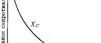
- As the frequency of the current increases, the reactance of the coil increases;
- It has the property of storing energy - when the current is turned off, the stored energy tends to compensate for the drop in current.
Coil connection diagrams
As a radio element, inductor coils have connection properties that are completely identical to resistor connections.
Parallel connection
Parallel connection:
L=1/(1/L1+1/L2+…+1/Ln).
For two elements the formula simplifies:
L=L1∙L2/(L1+L2).
Serial connection
The total value of a series connection is equal to the sum of the inductances:
L=L1+L2+…+Ln.
Connection types
Coil quality factor
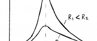
One of the most important qualities of coils is quality factor. This parameter represents the ratio of reactive (inductive) resistance to active. Active resistance is the resistance of the conductor from which the element is made; it can be considered constant, with the exception of the temperature coefficient of resistance of the material from which the wire is made.
Reactance is directly proportional to frequency. The formula for calculating the quality factor is as follows:
Q=2∙π∙f∙L/R,
Where:
- π – pi number, ≈3.14,
- f – frequency,
- R – resistance.
Note! As the signal frequency increases, the quality factor of the inductor increases.
Single turn circuit and coil
The inductance of a loop representing a turn of wire depends on the amount of current flowing and the magnetic flux passing through the loop. For the inductance of the circuit, the formula determines the parameter, respectively, through the flux and current strength:
L=F/I.
The weakening of the magnetic flux due to the diamagnetic properties of the environment reduces the inductance.
The parameter for a multi-turn coil is proportional to the square of the number of turns, since not only the magnetic flux from each turn increases, but also the flux linkage:
L=L1∙N2.
In order to calculate the inductance of a coil, the formula must take into account not only the number of turns, but also the type of winding and geometric dimensions.
Unit and calculation formulas
Capacitance, an electrical property capable of storing charges, is measured in farads (F) and is designated C. The value is named after the English physicist Michael Faraday. A capacitor with a capacity of 1 farad is capable of storing a charge of 1 coulomb on the plates with a voltage of 1 volt. The value of C is always positive.
Mathematical expression for farad
The capacitance of a capacitor is a constant value indicating the potential ability to store energy. The amount of charge stored at any given moment is determined by the equation Q=CV, where V is the applied voltage. Thus, by adjusting the voltage on the plates, the charge can be increased or decreased. This capacitance formula in the form C=Q/V in unit values determines how the capacitance of a capacitor is measured in SI and is the mathematical expression for the farad.
Electronics experts consider the unit of one farad not very practical, since it represents a huge value. Even 1/1000 F is a very large capacity. Typically, the following values are used for actual electrical components:
- picofarad - 10-12 F;
- nanofarad - 10-9 F;
- microfarad - 10-6 F.
You might be interested in this: The concept and determination of electrical power using formulas
The dielectric constant
The factor by which an insulator determines the capacitance of a capacitor is called dielectric constant. The generalized formula for calculating the capacitance of a parallel plate capacitor is represented by the expression C= ε (A / d), where:
- A is the area of the smaller plate;
- d is the distance between them;
- ε is the absolute permeability of the dielectric material used.
The dielectric constant of vacuum ε0 is a constant and has a value of 8.84x10⁻¹² farads per meter. Typically, the conductive plates are separated by a layer of insulating material rather than a vacuum. To find the capacitance of a capacitor whose plates are in the air, you can use the value ε0. The difference in dielectric constant of the atmosphere and vacuum can be neglected, since their values are very close.
In practice, formulas for finding the capacitance of a capacitor use relative dielectric constant as a coefficient, meaning how much the electric field between charges decreases in a dielectric compared to a vacuum. Some values of this value for various materials:
- 1.0006 - air;
- 2.5—3.5 — paper;
- 3—10 — glass;
- 5-7 - mica.
Since the efficiency of a capacitor depends on the insulator used in it, its quality as a storage device can be determined through its specific capacitance - a value equal to the ratio of the capacitance to the volume of the dielectric.
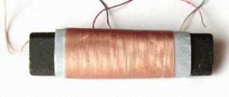
Solenoid
The solenoid differs from a conventional coil in two ways:
- The length of the winding exceeds the diameter several times;
- The thickness of the winding is also several times smaller than the diameter of the coil.
Solenoidal coil type
The solenoid parameters can be found from the following expression:
L=µ0N2S/l,
Where:
- µ0 – magnetic constant;
- N – number of turns;
- S – cross-sectional area of the winding;
- l – winding length.
Important! The above expression is valid for a solenoid without a core. Otherwise, it is necessary to additionally introduce a factor µ, which is equal to the magnetic permeability of the core.
Note! Using a movable core, it is possible to quickly change the parameters of the solenoid.
The greater the magnetic permeability of the core, the more the final value will increase.
Necessary formulas for calculations
To find the inductance of the solenoid, the following formula is applied:
- L= µ0n2V,
where µ0 shows the magnetic permeability of the vacuum, n is the number of turns, V is the volume of the solenoid.
You can also calculate the inductance of the solenoid using another formula:
- L = µ0N2S : l,
where S is the cross-sectional area and l is the length of the solenoid.
To find the inductance of the solenoid, any formula is used that is suitable for solving the given problem.
Toroidal coil (ring core coil)
The toroidal type of winding is calculated using a special formula, which assumes that a solenoid with an infinite length is used. To determine the inductance, the formula for the torus is as follows:
L=µ∙µ0N2S/(2π∙r),
where r is the average radius of the toroidal core.
A ring core of rectangular cross-section can be found using the following formula:
L=µ∙µ0N2S∙h/(2π)∙ln(R/r),
Where:
r – internal radius of the core;
R – outer radius;
h – height.
Important! The second formula allows you to find out the result with greater accuracy.
Toroidal winding
Long straight conductor
How to find the inductance of a straight conductor? There is a formula that gives the exact value provided that the conductor has a length significantly greater than its thickness:
L=µ0/(2π)∙l(µeln(l/r+1/4µi),
Where:
- µe and µi – magnetic permeability of the medium and conductor material, respectively;
- l and r are the length and radius of the conductor.
What magnetic permeability a conductor has can be found out from reference materials.
Device characteristics
The most important characteristic of a storage device is capacity. The charging time depends on it when the device is connected to a power source. The discharge time is directly related to the value of the load resistance: the higher it is, the faster the process of releasing the accumulated energy occurs. This capacity is determined by the following expression:
It will be interesting➡ What is the polarity of a capacitor and how to determine it?
C = E*Eo*S / d, where E is the relative dielectric constant of the medium (reference value), S is the area of the plates, d is the distance between them. In addition to capacity, the capacitor is characterized by a number of parameters, such as:
- specific capacitance - determines the ratio of the capacitance to the mass of the dielectric;
- operating voltage - the nominal value that the device can withstand when applied to the plates of the element;
- temperature stability - the range in which the capacitance of the capacitor practically does not change;
- insulation resistance - characterized by the self-discharge of the device and determined by the leakage current;
- equivalent resistance - consists of losses generated at the terminals of the device and the dielectric layer;
- absorption - the process of the emergence of a potential difference on the plates after the device is discharged to zero;
- capacitance - a decrease in conductivity when alternating current is supplied;
- polarity - due to the physical properties of the material used in manufacturing, the capacitor can operate correctly only if a potential with a certain sign is applied to the plates;
- equivalent inductance is a parasitic parameter that appears on the contacts of the device and turns the capacitor into an oscillating circuit.
Tables of maximum capacitance values.
Oscillatory circuit
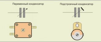
A capacitance and an inductive element connected in a circuit form an oscillatory circuit with pronounced frequency properties and will be a resonant system. The system uses a capacitor, changing the capacitance of which, you can correct the frequency properties.
Series and parallel oscillatory circuits
If you measure the resonant frequency using a known capacitor, you can determine the inductance of the coil.
Inductance is an important element in various fields of electrical engineering. For proper use, you need to know all the parameters of the elements used.
A device that allows you to determine the parameters of inductors, including quality factor, may be called an L-meter or Q-meter.
Q-meter for measuring quality factor
Practical measurements
The capacitance value of the capacitor is indicated on the case in fractional farads or using a color code. But over time, components can lose their qualities, so for some critical cases the consequences may be unacceptable. There are other circumstances that require measurements. For example, the need to know the total capacity of a circuit or piece of electrical equipment. There are no devices that directly read the capacitance, but the value can be calculated manually or by processors integrated into the measuring devices.
To detect the actual capacitance, an oscilloscope is often used as a means of measuring the time constant (t). This value indicates the time in seconds during which the capacitor is charged by 63%, and is equal to the product of the circuit resistance in ohms and the circuit capacitance in farads: t = RC. An oscilloscope makes it easy to determine the time constant and makes it possible to use calculations to find the required capacitance.
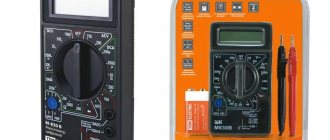
There are also many models of amateur and professional electronic measuring equipment equipped with functions for testing capacitors. Many digital multimeters have the ability to determine capacitance. These devices are capable of charging and discharging a capacitor in a controlled manner with a known current and, by analyzing the increase in the resulting voltage, produce a fairly accurate result. The only drawback of most of these devices is the relatively narrow range of measured values.
You might be interested in this: Connection diagram for a single-phase electricity meter Mercury 201
More complex and specialized tools are bridge meters, which test capacitors in a bridge circuit. This indirect measurement method provides high accuracy. Modern devices of this type are equipped with digital displays and the ability to be used automatically in a production environment, they can be interfaced with computers and export readings for external monitoring.