Analog multimeter
This type of multimeter displays measurement readings using an arrow, under which there is a display with different scales of values. Each scale displays the readings of a particular measurement, which are signed directly on the display.
But for beginners, such a multimeter will not be the best choice, since it is quite difficult to understand all the symbols that are on the display. This may lead to incorrect understanding of the measurement results.
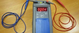
Digital multimeter
Unlike analogue ones, this multimeter allows you to easily determine the quantities of interest, while its measurement accuracy is much higher compared to pointer devices.
Also, the presence of a switch between different characteristics of electricity eliminates the possibility of confusing one or another value, since the user does not need to understand the gradation of the reading scale.
The measurement results are displayed on the display (in earlier models - LED, and in modern ones - liquid crystal). Due to this, the digital multimeter is comfortable for professionals and simple and easy to use for beginners.
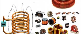
Inductance meter for multimeter
Despite the fact that it is rare to determine inductance when working with electronics, it is still sometimes necessary, and multimeters that measure inductance are quite difficult to find. In this situation, a special attachment to a multimeter will help, allowing you to measure inductance.
Often, for such a set-top box, a digital multimeter is used that is set to measure voltage with a measurement accuracy threshold of 200 mV, which can be purchased ready-made at any electrical and radio equipment store. This will allow you to make a simple attachment for a digital multimeter.
Inductive reactance - units of measurement
This value is measured in ohms. The unit of measurement used here is the same as for a resistor, although they are of a different nature. The quantity under consideration is generated by an electromotive force that counteracts the change taking place. The usual occurs due to the dissipation of energy when electrons pass through a conductor.
Magnetic field of an inductive element
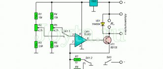
Set-top box assembly
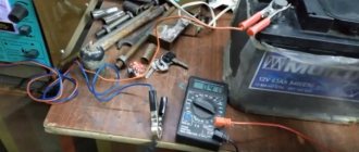
You can assemble a tester attachment for a multimeter for measuring inductance without any problems at home, having basic knowledge and skills in the field of radio engineering and soldering microcircuits.
In the board circuit, you can use transistors KT361B, KT361G and KT3701 with any letter markers, but to obtain more accurate measurements it is better to use transistors marked KT362B and KT363.
These transistors are installed on the board in positions VT1 and VT2. At position VT3 it is necessary to install a silicon transistor with a pnp structure, for example, KT209V with any letter marking. Positions VT4 and VT5 are for buffer amplifiers.
Most high-frequency transistors are suitable, with h21E parameters for one not less than 150, and for another more than 50.
For positions VD and VD2, any high-frequency silicon diodes are suitable.
The resistor can be chosen MLT 0.125 or similar. Capacitor C1 is taken with a nominal capacity of 25330 pF, since it is responsible for the accuracy of measurements and its value should be selected with a deviation of no more than 1%.
Such a capacitor can be made by combining thermally stable capacitors of different capacities (for example, 2 at 10000 pF, 1 at 5100 pF and 1 at 220 pF). For other positions, any small-sized electrolytic and ceramic capacitors with an acceptable spread of 1.5-2 times are suitable.
Contact wires to the board (position X1) can be soldered or connected using spring clamps for “acoustic” wires. Connector X3 is intended for connecting the set-top box to a multimeter (frequency meter).
It is better to take shorter wires to bananas and crocodiles in order to reduce the influence of their own inductance on the measurement readings. In the place where the wires are soldered to the board, the connection should be additionally secured with a drop of hot-melt adhesive.
If it is necessary to regulate the measurement range, you can add a switch connector to the board (for example, for three ranges).
Measurement options
The inductance of a coil in physics is determined by performing calculations. However, this value can not only be calculated, but also measured. This is done using a direct or indirect method.
Direct method
To measure the inductance of a coil using this method, it is necessary to use special bridge or direct-indicating devices. With their help, you can obtain the most accurate data that will help you select the required coil for the circuit.
The procedure for carrying out measurements includes the following steps :
- A coil is connected to the direct indicating device.
- After this, the measurement ranges are gradually changed. This is done until the result obtained is approximately in the middle of the interval.
- The result obtained is recorded and calculated taking into account the division value of the device, as well as the coefficient corresponding to the position of the switch.
The direct measurement method can also be used to determine inductance using a bridge device. It has a more accurate scale, so it allows you to obtain reliable data.
The measurement is performed by performing the following actions:
- The switched-on bridge device is connected to a coil, the inductance of which must be determined.
- Similar to a direct indicating device, the measurement intervals are switched.
- After each such action, the handle of the bridge balancing regulator is alternately moved to one and the other limit position.
- Once you have determined the range within which the bridge will be balanced, you can proceed further.
- At the next stage of measurement, the dial indicator is gradually moved.
- After the sound disappears from the speaker of the device, it is necessary to record the indicators.
- They are then calculated in accordance with the scale division price and the provided coefficient.
You may be interested in: Features of current resonance
Indirect definition
In order to measure the self-induction coefficient, it is necessary to carry out several preparatory measures. First of all, you need to assemble the measuring circuit according to the standard circuit, and also prepare all the necessary devices (sinusoidal voltage generator, frequency meter, as well as a milliammeter and voltmeter designed for alternating current).
The procedure for determining the parameter:
- A voltmeter is connected in parallel to the generator output. It must be switched to a mode in which the upper limit value corresponds to a voltage of 3-5 volts.
- The frequency meter is connected in the same way.
- The second chain is assembled separately. It connects a milliammeter and a coil in series, the inductance of which needs to be determined.
- Then both circuits are connected in parallel to each other.
- The connected generator is set to generate sinusoidal voltage.
- By changing the frequency, they achieve such operation of the devices that the voltmeter will show approximately 2 volts. In this case, the current on the milliammeter will gradually decrease.
- After this, the frequency meter handle is moved to the position corresponding to the measurement frequency.
- Once these steps are completed, the values can be captured.
The obtained data is converted into SI, and then all the necessary calculations are performed. The first step is to determine the inductive reactance. To do this, the values of the devices are substituted into the following relationship: X = U/I, where U is the voltage and I is the current. The result of the calculations will be expressed in ohms.
After this, the inductance is calculated using the formula L=X/2 πF. It uses the following conventions:
- X is inductive reactance;
- π is a mathematical constant (approximately 3.14);
- F is the frequency in hertz at which the measurements were taken.
Inductance is an important physical parameter that allows you to determine the magnetic properties of an electrical circuit. By measuring it accurately and correctly carrying out the required calculations, you can obtain reliable data that will be needed when choosing a coil.
Multimeter attachment housing
The body can be made from a ready-made box of a suitable size or you can make the box yourself. You can choose any material, for example, plastic or thin fiberglass. The box is made to the size of the board, and holes are prepared in it for its fastening. Holes are also made for wiring connections. Everything is fixed with small screws.
The set-top box is powered from the mains using a power supply with a voltage of 12 V.
Setting up an inductance meter
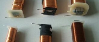
In order to calibrate the attachment for measuring inductance, you will need several induction coils with known inductance (for example, 100 μH and 15 μH).
The coils are connected one by one to the attachment and, depending on the inductance, the trimmer resistor slider on the multimeter screen sets the value 100.0 for a 100 µH coil and 15 for a 15 µH coil with an accuracy of 5%.
Using the same method, the device is configured in other ranges. An important factor is that accurate test inductor values are required to accurately calibrate the attachment.
An alternative method for determining inductance is the LIMP program. But this method requires some preparation and understanding of how the program works.
But in both the first and second cases, the accuracy of such inductance measurements will not be very high. This inductance meter is not suitable for working with high-precision equipment, but for home use or for radio amateurs it will be an excellent assistant.
What factors does resistance depend on?
Changing the current creates an electromagnetic field of variable intensity. The result of its effect on the conductor is to counteract the current change that occurs.
This opposition is called reactance. There are two types of it: inductive and capacitive. The first is created when there is an inductive element in the circuit, the second - a capacitor.
In a situation where a coil is present in the circuit, its response increases as the frequency increases.
Circuit in which induction occurs
When its inductance decreases, the opposing force also becomes less. As it increases, it increases.
Inductive reactance is significantly related to the shape the conductor takes. It is also present on a separate wire lying straight. However, if there is another one nearby, it will have an additional effect, which will affect the value under consideration.
You may be interested in this Features of the ripple coefficient
The characteristic of an individual wire under consideration can be determined depending on its thickness, but it is in no way related to its cross-section.
The principle of operation of electromotive force
Carrying out inductance measurements
After assembly, the multimeter attachment must be tested. There are several ways to check your device:
- Determination of the inductance of the measuring attachment. To do this, you need to short-circuit two wires intended for connection to the inductive coil. For example, with a length of each wire and jumper of 3 cm, one turn of the induction coil is formed. This turn has an inductance of 0.1 - 0.2 μH. When determining inductance above 5 μH, this error is not taken into account in the calculations. In the range of 0.5 - 5 µH, when measuring, it is necessary to take into account the inductance of the device. Readings less than 0.5 µH are approximate.
- Measuring an unknown inductance value. Knowing the frequency of the coil, using a simplified formula for calculating inductance, you can determine this value.
- In the case when the response threshold of silicon pn junctions is higher than the amplitude of the measured electrical circuit (from 70 to 80 mV), it is possible to measure the inductance of the coils directly in the circuit itself (after de-energizing it). Since the set-top box’s own capacitance is of great importance (25330 pF), the error in such measurements will be no more than 5%, provided that the capacitance of the measured circuit does not exceed 1200 pF.
When connecting the set-top box directly to the coils located on the board, 30 centimeters long wiring with clamps for fixation or probes is used. The wires are twisted at the rate of one turn per centimeter of length. In this case, the inductance of the set-top box is formed in the range of 0.5 - 0.6 μH, which also must be taken into account when measuring inductance.
Calculation methods
There are several basic ways to determine the inductance of a coil. All formulas that will be used in the calculations can be easily found in reference books or on the Internet. The whole calculation process is quite simple and will not be difficult for people with basic mathematical and physical knowledge.
You may be interested in this Features of current operation
Through current
This calculation is considered the simplest way to determine the inductance of a coil. The formula through current follows from the term itself. What is the inductance of the coil can be determined by the formula: L=Ф/I, where:
- L - circuit inductance (in Henry);
- F is the magnitude of the magnetic flux, measured in webers;
- I is the current strength in the coil (in amperes).
This formula is only suitable for a single-turn circuit. If the coil consists of several turns, then instead of the magnetic flux value, the total flux (total value) is used. When the same magnetic flux passes through all the turns, then to determine the total value it is enough to multiply the value of one of them by the total number.
Finite Length Solenoid
The solenoid is a thin long coil, where the thickness of the winding is significantly less than the diameter. In this case, calculations are carried out using the same formula as through current strength, only the magnitude of the magnetic flux will be determined as follows: Ф=µ0NS/l, where:
- µ0 is the magnetic permeability of the medium, determined from lookup tables (for air, which is taken by default in most calculations, it is equal to 0.00000126 henry/meter);
- N is the number of turns in the coil;
- S is the cross-sectional area of the coil, measured in square meters;
- l is the length of the solenoid in meters.
The self-induction coefficient of the solenoid can also be calculated based on the method for determining the energy of the magnetic flux of the field. This is a simpler option, but it requires some quantities. The formula for finding inductance is L=2W/I 2, where:
- W is the magnetic flux energy, measured in joules;
- I is the current strength in amperes.
Toroidal core coil
In most cases, a toroidal coil is wound on a core made of a material with high magnetic permeability. In this case, to calculate the inductance, you can use the formula for a straight solenoid of infinite length. It has the following form: L=N µ0 µS/2 πr, where:
- N is the number of coil turns;
- µ—relative magnetic permeability;
- µ0—magnetic constant;
- S is the cross-sectional area of the core;
- π is a mathematical constant equal to 3.14;
- r is the average radius of the torus.
You may be interested in Electronic voltage converter from 12 V to 220 V
Long conductor
Most of these quasi-linear conductors have a circular cross-section. In this case, the value of the self-induction coefficient will be determined by the standard formula for approximate calculations: L= µ0l (µelnl/r+ µi/4)/2 π. The following notations are used here:
- l is the length of the conductor in meters;
- r is the radius of the wire cross-section, measured in meters;
- µ0—magnetic constant;
- µi is the relative magnetic permeability characteristic of the material from which the conductor is made;
- µe is the relative magnetic permeability of the external environment (most often the value for vacuum is taken to be 1);
- π—pi number;
- ln is the notation for logarithm.