DIY electrostatic generator | 2 Schemes
The operating principle of a static electricity generator (also called electrophore machines) is that the disks rotate relative to each other in opposite directions and create positive and negative charges. When the disks rotate, as charges accumulate, a discharge occurs—lightning between the electrodes.
How it works - theory
The rotation of disks with metal sectors leads to the transfer of electrical charge inside the machine, which is stored in capacitors until a spark or leakage charge occurs.
The most important parts in an electrophore unit are neutralizers. These are two jumpers with brushes installed in a cross. If at least one of the four brushes is moved away from the segments, the machine stops working. Although it would seem that the disks are rotating, they are electrified by friction with the air, which means electricity is generated.
The neutralizer does the following: it drags the charge from one half of the disk to the other and the disk is not just charged, but selectively charged - not over the entire plane.
In other words, the disk collects charges from the air, and the neutralizers redistribute them. The charge is removed by the brush, moves along the conductor to the opposite brush, and at the moment when a segment of the second disk appears opposite the segment, it jumps to it.
Next, this segment approaches the brush of the second neutralizer and the process is repeated, but on another disk. Thus, a circulation of charges occurs between the disks, during which the air between the segments is ionized and separated. As a result of pumping, the voltage increases; in addition, the machine has the effect of moving the capacitor plates apart, which also helps to increase the voltage.
A miniature device for creating such harmless lightning (but not for microelectronics) is easy to make with your own hands.
This electrostatic generator is capable of generating over 20,000 volts, but the low current makes it safe to use without special precautions.
Device characteristics
- Height: about 140mm
- Width: approximately 120 mm
- Power: 3V 0.3A
- Static charge: 20 kV
- Disc diameter: 120 mm
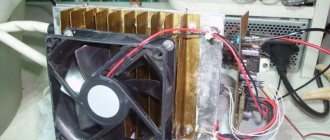
There is no need to turn anything by hand (as was the case in the prototype of the century before last) - everything is done by 2 electric motors. Just press the power button and wait a while until the charge accumulates on the electrodes.
Materials and components
You will need for installation: a soldering iron and solder, a screwdriver and pliers. Two motors from old CD players and all sorts of small fastenings.
The generator runs on two AA batteries and is capable of creating discharges 2 cm long. The most difficult thing here is the 120 mm discs. They need to be made according to this principle: take two laser discs from a CD or DVD. Glue the segments with aluminum tape (25 sectors). Glue the discs to the motors. Make brushes from aluminum strips.
If everything is done and configured as necessary, the spark will reach a size of about 20 mm, and the discharge will strike every 0.5 seconds.
2shemi.ru
How it works - theory
The rotation of disks with metal sectors leads to the transfer of electrical charge inside the machine, which is stored in capacitors until a spark or leakage charge occurs.
The most important parts in an electrophore unit are neutralizers. These are two jumpers with brushes installed in a cross. If at least one of the four brushes is moved away from the segments, the machine stops working. Although it would seem that the disks are rotating, they are electrified by friction with the air, which means electricity is generated.
The neutralizer does the following: it drags the charge from one half of the disk to the other and the disk is not just charged, but selectively charged - not over the entire plane.
In other words, the disk collects charges from the air, and the neutralizers redistribute them. The charge is removed by the brush, moves along the conductor to the opposite brush, and at the moment when a segment of the second disk appears opposite the segment, it jumps to it.
Next, this segment approaches the brush of the second neutralizer and the process is repeated, but on another disk. Thus, a circulation of charges occurs between the disks, during which the air between the segments is ionized and separated. As a result of pumping, the voltage increases; in addition, the machine has the effect of moving the capacitor plates apart, which also helps to increase the voltage.
A miniature device for creating such harmless lightning (but not for microelectronics) is easy to make with your own hands.
This electrostatic generator is capable of generating over 20,000 volts, but the low current makes it safe to use without special precautions.
Instructions for assembling a static electricity generator with your own hands
I had already created several static electricity generators before and these projects always aroused great interest. They are a lot of fun to play with and allow you to do a lot of different tricks with ESD. For example, you can shock your friends (and yourself), force sand or dust particles with your hands to behave strangely, since they are susceptible to static charges. You can also attract a stream of water, charge paper so that it sticks to the wall, and perform many other magical tricks.
The video above demonstrates the assembly process for this project, and the text version below will give you step-by-step instructions. This is the third version of my static electricity generator, and it is the cheapest. It allows you to create a charge about the same as what happens when you catch a spark from a carpet while walking on it in your pajamas.
The USB ionizer, which is the main component of the project, can be found here: link
We will need:
- Ionizer.
- Insulated wire.
- Heat-shrink tubing.
- Hot glue.
- Solder and soldering iron.
- Button batteries 1.5v.
- Insulating tape.
Step 1: Disassemble the ionizer
Ionizers of this type are very easy to disassemble. If you use them as intended, the case will most likely crack itself within a week. Using mono pliers, it is easy to open the case and gain access to the device board. By the way, I would like to note that I would not connect such a device to the USB port of a computer. It is better not to connect high-voltage devices to the computer at all.
If you pay attention to the last two pictures, you will notice that I divided the device into two sections. The first part, close to the USB, is a converter that converts the DC current from the USB into alternating current, which then passes through a tiny transformer to the second part of the device. The second part consists of a chain of four series voltage amplifiers, which require alternating current to operate. But at the end we have a constant current that is sent to the white wire.
The circuit is just what we need to get a static charge, but we need to modify it so that it runs on batteries.
Step 2: Add Input and Output Wires
To change the circuit to the state we need, first of all we will get rid of USB. Let's unscrew the two ears on the sides, and the port will only be held on by 4 pins. Let's lean the soldering iron against all the pins at once and release the board from the USB port.
On the other side of the board there are symbols by which you can determine which terminal is for positive charge and which for ground, they are respectively marked with the symbols V+ and GND. I soldered wires to these terminals, the other ends of the wires will be connected to the batteries.
The last picture shows me working on the other side of the board, where I desolder the short output wire and solder a new, much longer one in its place.
Step 3: Isolate the Circuit
We need to isolate the circuit from the high voltage it will generate, otherwise it will fry itself. Before putting everything into the heat shrink tubing, I first went over the diagram with hot glue, this allowed me to create a stronger connection for the wires than just a small drop of solder. I then placed heat shrink tubing over the unit and used low heat to gently secure it in place. The ends of the tube were left not too pinched and I also filled them with hot glue. These ionizers come with an indicator light to let you know they are working, so I removed some heat shrink where the diode was.
Step 4: Power up the generator
The USB power supplies for which such devices are designed provide an output of 5 Volts DC. It is quite difficult to find a battery with the same voltage, but usually electrical appliances can operate in a small voltage range, so we can combine three 1.5V batteries and this should be enough.
To connect them, expose a small section of the ground wire (also leaving a long insulated end) and bend it so that you can press this section to the negative terminal of the batteries. I added a little solder to the bare part and it began to hold its shape.
Then place a pack of batteries between the two wires, aligning the positive terminal with the positive terminal of the batteries, and connecting the ground wire to the negative terminal of the batteries. A small amount of electrical tape will hold the batteries together and press the wires tightly to their terminals.
If desired, you can solder a switch to the positive wire, but I decided that the device would always be on. To turn it off, I simply slide a small plastic plate between the batteries and it breaks the connection.
Step 5: Conclusion
The device is fully operational at this stage. In order for it to charge your body (or any conductive object), the output wire must touch your skin, while the end of the long ground wire must touch the surface you are standing on. A more conductive surface will allow the device to perform better, as it will allow for a greater charge differential between you and your surroundings.
For my previous generators, I created Velcro connections that allowed me to securely secure the output wires to my body and attach the ground wire to the bottom of my sole.
That's all! I hope you enjoyed reading about my project.
masterclub.online
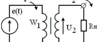
Operating principle
Static electricity is widely used in industry to impart temporary adhesive properties to materials. The results you need can be achieved in a simple, clean and cost-effective way using the Fraser device system.
This system consists of a static charge generator and one of the ionizing devices. The generator produces DC voltage up to 30 kV. Ionizer emitters convert this voltage and emits a cloud of ions. Materials that pass through this cloud are charged with a charge polarity similar to that of the generator on the ionizer side and with a mirror charge generated by the ground on the opposite side.
A non-conducting barrier (material) is placed between the two charges, which causes adhesion. If the barrier is a good insulator, such as a synthetic film, then a very high degree of adhesion can be achieved. If it is a weak conductor, such as paper, adhesion will not be as significant, because most of the current will flow through the material.
7 Series Static Generators (from left to right) 7360, 7333 (all other generator models have the same appearance as the 7360)
| Description | |
| Design | Housing made of 1.5 mm thick steel with mounting hardware. Weight: 9 kg. |
| Power supply and contacts | Input voltage: 22-26 V DC or 220 V AC (depending on model). Input current: max. 2.0 A under all operating conditions. Fuse: 2.5 A/250 V AC. 8-pin AOPULO connector on front panel. Pin 1: 24 V input. Pin 2: ground (24 V output). Pin 3: fault indicator (“on” = error). Pin 4: High voltage switch (grounded signal = voltage applied). Pin 5: operational indicator (“on” = working). Pin 6: voltage level adjustment (0-10 V). Pin 7: High voltage control signal return. can be supplied with a 5 m long control cable with an 8-pin connector. |
| Output and control | Switches on the case for selecting remote/local device control mode and current/voltage control mode. Variable output power (0 - 30/50 kV/1.5 mA), adjustable remotely via pin No. 6 "0-10 V" or the "Adjust" potentiometer on the instrument panel. 3.5″ LED display displaying the current value of voltage or current (LED indication of the selected parameter). Ripple less than 2% peak to peak at maximum load. The adjustment error is less than 1%. Protected from overloads, sparks, short circuits. The customer determines the polarity of the device when ordering. |
| Permissible load | Up to 10 m - static generation device and cable, depending on connecting one or two devices to the connector. Possibility of using an external connector block to connect more devices. |
| Working conditions | Clean, dry room, max. temperature: +40°C, no condensation. |
| Standards | Directive 72/23 EEC (low voltage). EMC Directive: 89/336/EEC. |
DIY static electricity generator
The essence of the electrophore machine
Assembling the Wimshurst machine
In this video tutorial we will assemble an electrophore machine, which is a static electricity generator. At the beginning, general questions about the purpose and design of this machine are discussed, then all the steps for making it yourself are shown in detail.
Check out the selection of hand generators at this Chinese store.
What is an electrophore machine?
The device consists of a base on which its parts are attached. It also includes two racks with axles on which two disks with a metallized coating are mounted. There are also two Leyden jars, which are essentially capacitors or stores of charged particles. Dischargers, which function as the charge of the capacitors accumulate, remove charged particles from the front and rear sides of the disks. The discs are driven by a belt drive. We turn the handle and due to this, the disks rotate.
The first static electricity generators were simultaneously invented in Germany at the same time by August Toepler and, independently of him, by Wilhelm Goltz. The operating principle of an electrophore machine. As the disks rotate relative to each other in opposite directions, they create positive and negative charges. As the disks rotate, as charges accumulate, a discharge occurs.
The authors of the video decided to make this machine, which can be repeated with your own hands in normal home conditions. There are several examples on websites on the Internet of creating such a generator, but this design will have an engine.
First, drawings of the future machine were made. First of all, the disk parameters were calculated. After the preliminary work was done, we began to create the device.
Main details
The machine will consist of the following elements. These are 2 disks that will rotate in opposite directions, they will be made from CDs. Two motors from a computer cooler that will drive them. The disk will be glued with double-sided tape to the motor rotor. The engine itself is attached to the rack. The stands will be made of plexiglass. Leyden jars will also be used. This is an empty metal container from which there is one contact, then a polystyrene dielectric and a brass contact.
Manufacturing of electrophore machine
First you need to remove the coating from the disk to get a transparent blank. To do this we use a stationery knife. To create a working disk, you need sketches, they are made on a computer. The petal template can be made from a suitable material; a bank card is good for this.
Now, using the template, we begin marking on the tape. We attach the template and cut out all the necessary fragments. A total of 20 petals were cut out onto one disk. There should be 20 sections. The angle between the two petals is 18 degrees. Marking is done using a regular checkered sheet and a protractor. Now we place the disk exactly in the middle of the coordinates, using a knife or awl to make notches of 18 degrees. Glue the petals according to the lines. The second disc was made in exact analogy with the first disc. It has been machined to provide clearance.
Remove the yellow wire from the motor. We cut off the stiffeners so that the engine can be disconnected. Some space must be left for mounting holes.
izobreteniya.net
Claim
A static generator of electrical energy, including a housing with a package of metal plates of both signs, separated by a layer of stabilized monocrystalline ferroelectric, while in the package all layers are tightly adjacent to each other, characterized in that the metal plates are made of dissimilar conductors with different concentrations of free electrons: two different metals, for example antimony-bismuth, iron-nickel, titanium-aluminium, or various alloys, for example chromel-alumel, chromel-kopel, or combinations of metal and alloy, for example iron-copel, antimony-alumel, bismuth-chromel, wherein the package plates will include at least one elementary cell, which consists of one ferroelectric and two dissimilar conductors which are placed in the following sequence: conductor - ferroelectric - conductor, and if there is more than one elementary cell in the package, they are connected to a source of electrical energy consumption in series, or in parallel, or combined - several elementary cells are connected in series, and several elementary cells are connected in parallel.
How to make a static voltage generator for $5
In this article we will look at how to make a static voltage generator.
With it, you can conduct various experiments, arrange pranks for friends, show tricks, and so on. Static voltage can distort the flow of water, attract various objects, for example, sand, it can charge pieces of paper and much more. The author decided to use a USB air ionizer as the main element for the homemade product.
Materials and tools for homemade work: - USB air ionizer; - heat-shrink tubing; - insulated wire; - hot glue; - soldering iron with solder; — three 1.5 V batteries; - electrical tape.
Homemade manufacturing process:
Step one. Disassembling the ionizer
First you need to disassemble the ionizer. According to the author, this is done very simply. You need to use a needle or knife blade to split the plastic halves of the ionizer. Sometimes before this you need to unscrew a couple of screws that hold the case together. According to the author, such devices generally interact poorly with a computer, so he does not recommend connecting USB ionizers directly to a laptop or computer. It is best to use an extension cord.
Conventionally, the converter circuit can be divided into two parts.
One half of the circuit, the one closest to the USB, converts the DC current from the USB port to AC. This alternating current is then supplied to the second half of the device, passing through a miniature transformer. In the second half there are four voltage multipliers, which are connected in series. As a result, a high voltage is generated, which is applied to the white wire. In principle, this circuit is almost ready to create static voltage, but the author is modifying it to run on batteries. Step two. Adding input and output wires
Now the author is modifying the device to suit himself. The first step is to remove the USB connector. To do this, you need to bend the two plates that secure the port to the board, and then simultaneously touch the four pins of the connector with a soldering iron. Well, or unsolder one at a time, gradually bending the connector away from the board.
Turning the board over, you can see markings that allow you to determine which contacts to connect the power to.
These are the designations V+ and GND (ground, minus). You need to solder wires to each contact; they will be used to connect the battery. The author also removed the white outgoing wire and soldered a longer one in its place. Step three. Isolate the circuit
To prevent the board from receiving an electric shock during operation or destroying itself, it must be well insulated.
For this, the author insulates the soldering area using hot glue. In addition, hot glue additionally secures the wires. Next, the author takes a heat-shrinkable tube and pulls it onto the board.
After carefully heating the heat shrink with fire, it shrinks, but there are holes at the edges. These holes are then filled with hot glue. The device is now well insulated. There is also an LED on the board that shows whether the device is working. To make the LED visible, you need to carefully grind off the heat shrink over it.
Step four.
Connecting the generator Probably everyone knows that USB supplies power at 5V, but most electronics connected to computers can operate at lower voltages. Since finding a battery that would produce 5V is problematic, the author decided to use 4.5V instead of five, connecting 3 1.5V batteries in series. The battery connection scheme is such that the device is always on by default. To turn it off, you need to insert a piece of plastic or piece of paper between the batteries, thereby opening the circuit. You can also make a switch. The batteries are held in place by a piece of electrical tape. At this point you need to connect a long ground wire to the negative wire.
Step five. The final stage. Device testing
To turn on the device, you will need to connect two cables.
One cable connects to the human body (outgoing red), the second black is ground, it connects to the object with which you need to interact. For example, the black wire can be connected to a water tap, and the red wire to itself, so you can use your finger to deflect the flow of water. Source Delivery of new homemade products by mail
Receive a selection of new homemade products by mail. No spam, only useful ideas!
*By filling out the form you agree to the processing of personal data
Become the author of the site, publish your own articles, descriptions of homemade products and pay for the text. Read more here.
usamodelkina.ru
DIY Van de Graaff generator
These are the instructions on how I built a DIY Van de Graaff Generator from some unwanted scraps. Here it is in the picture:
So, the first thing to do is to collect all the necessary components. They include: 1 pencil, two old dried pastes, a piece of PVC pipe, one dead light bulb, a long piece of rubber band, a paper clip, aluminum foil, tape, one small toy motor, a nine-volt battery, and some wire, and a wooden base tablet. Everything is visible in the photo:
The first step in your action will be to drill a hole for the tube at the base of the base. You need to take a drill with a feather drill of the required diameter so that the PVC tube fits tightly.
Next, you make two through holes through both sides of the tube. The distance between the holes is such that when inserting the paste and tension between the pastes of the gum, so that the elastic is slightly stretched. Make sure the rubber is not too tight otherwise it will stop the engine.
Then we make two more holes in the tube. The first hole should be drilled slightly higher than the first one on the same axis. The second hole should be directly perpendicular to the bottom one. Look carefully at the photo:
Now you need to remove the ink from the paste. I used tie tape, like the ones that come with trash bags, to clean out the paste. What you use, think for yourself.
Next, you cut a piece of paste to the length of the inner diameter of the PVC pipe. Then take a paperclip and cut a piece long enough so that the piece protrudes from the tube by at least a centimeter. See photo:
As you probably guessed, we will need two of these rollers. Before assembly, it is necessary to assemble the dielectric film. It is made from tape and our elastic band. The elastic band is covered with tape so that the adhesive sides are glued together. You don’t have to paste over the strip of tape, but simply put an elastic band on top to press it against our rollers.
Then we take a pencil eraser and assemble our structure as shown in the figure below. To ensure a reliable connection, the motor shaft is glued to the eraser and paper clip with super glue.
The next step is to add brushes that collect the charge. The lower brush, as shown in the picture on the left, passes through the hole in the lower part, the tip of the wire should be loosened. You should make sure that the brushes are close to the elastic, but should not touch it. The top brush, as shown in the picture on the right, goes through the top hole.
The next stage and finale is to cover the burnt out light bulb with a piece of aluminum foil. The key is to provide the aluminum with more charge in order to collect as much of it as possible. Then we connect the top wire to this foil on the lamp and insert our lamp-electrode onto the top of the entire structure. Well, now you know how to build a Van de Graaff generator yourself.
That's all! Well, now you can play with static electricity
For reference:
The operating principle of a Van de Graaff generator is very similar to that of a Wimshurst machine, but instead of rotating discs, it uses a moving belt on two pulleys. The belt is electrified by friction against the lower pulley (in large machines it is supplied with additional voltage from a high-voltage source, in small machines there is enough friction), and at the upper end of the belt the charge is removed and accumulates on the surface of the ball. Large Van de Graaff generators are capable of producing voltages of millions of volts and are several meters high.
sdelaysam-svoimirukami.ru
Making a perpetual electricity generator
Humanity has always strived to create alternative ways of producing electricity.
The result of these aspirations were solar and smoke generators, as well as other devices that make it possible to obtain electricity in a non-standard way. This material will provide an overview of a video on the manufacture of such a generator, which will allow you to generate electricity. Let's start with the author's video
We will need: - several ice trays; - Apple vinegar; - copper wires; - nails; - wire cutters.
First you need to cut the copper wires into 5 cm pieces. This can be done with your bare hands, but to make the job easier, we recommend using wire cutters.
Next, the resulting pieces need to be thoroughly twisted and screwed onto the top of the nail. These nails with wire need to be made according to the number of cells of the mold, so we advise you to be patient. The author, for example, has 32 cells and uses 16 nails.
Next, pour the apple cider vinegar into the ice cube trays. You need to fill it about halfway, but it’s okay if you poured a little more, since you can drain off the excess vinegar using a tube.
Next, we take nails with copper wire and place them in molds so that there is one nail and one wire in one mold, with the exception of the two outer cells. For greater clarity, we present the final result in the figure below.
The author's test using a multimeter showed that such a generator produces 2.5 volts. You can increase the voltage of a homemade generator by adding vinegar to the free cells and adding nails. Adding vinegar to 4 cells increased the power by 1 volt. To connect the LED you need 4.5 - 5 volts, so you will have to pour vinegar into 16 cells.
Let's move on to connecting the LED. It is enough to dip the contacts of the LED light bulb into the outermost cells with vinegar so that it lights up.
The author's test using all 32 cells showed that such a generator can produce 12 volts. Increasing the concentration of vinegar can increase the voltage.
The homemade generator is ready. Delivery of new homemade products to the post office
Receive a selection of new homemade products by email. No spam, only useful ideas!
*By filling out the form you agree to the processing of personal data
Become the author of the site, publish your own articles, descriptions of homemade products and pay for the text. Read more here.
usamodelkina.ru