Application
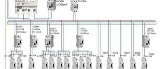
In the mine and mine, flammable gases such as methane, butane and propane accumulate, and there is coal dust, which is explosive. The use of a conventional power supply system with a solidly grounded neutral is unacceptable due to the fact that when phase voltage hits the electrical equipment housing, an electric arc occurs, which can cause a fire or explosion. Therefore, a power supply system with an isolated neutral is used.
In such a network, the phase voltage during a short circuit to the ground passes through some resistance much greater than the resistance of the ground electrode. Therefore, the short circuit is of relatively small magnitude and an electric arc usually does not occur.
Against the background of the operation of powerful equipment, this may not be noticed and will subsequently lead to an interphase short circuit, accompanied by an electric arc and an explosion of coal dust or gas.
To do this, in systems with an isolated neutral, the insulation condition of the monitored line is constantly checked, and the voltage supply is immediately turned off if the insulation resistance drops below a threshold level. Leakage relays perform this protective function.
Mining leakage relay RU-380/660
Home / Mine automation, starters and transformers / Mine leakage relay RU-380/660
Purpose
The RU-380/660 leakage relay is designed to protect people from electric shock and other dangerous consequences of current leaks to the ground in three-phase alternating current electrical networks with a frequency of 50 Hz and a voltage of 380 V and 660 V with an isolated transformer neutral.
Application area
In underground workings and on the surfaces of coal mines, hazardous for the explosion of methane gas and coal dust in accordance with the “Safety Rules in Coal Mines” PB 05-618-03 and mining enterprises in accordance with the “Unified Safety Rules for the Development of Ore, Nonmetallic and Placer Mines” mineral deposits using the underground method" PB 03-553-03.
Specifications
| Main settings | Meaning | |
| Specifications | TU 3148-015-62509866-2011 | |
| Explosion protection marking | RV Exd I | |
| Degree of protection | IP54 | |
| Rated supply voltage, V | 380/660 | |
| Rated power consumption, W, no more | 100 | |
| Actuation resistance for symmetrical three-phase leakage and network capacitance from 0 to 1 µF per phase, kOhm per phase, no more than: | 380 V | 10 |
| 660 V | 30 | |
| Actuation resistance for single-phase leakage and network capacitance from 0 to 1 µF/phase, kOhm, no more than: | 380 V | 12 |
| 660 V | 20 | |
| Response time with a single-phase leakage resistance of 1 kOhm and a network capacitance of 0 to 1 µF/phase, s, no more: | 380 V | 0,1 |
| 660 V | 0,1 | |
| Duration of automatic adjustment of the compensation device, s, no more | 0,1 | |
| Long-term leakage current when the network capacitance changes from 0 to 1 µF per phase, A, no more | 0,025 | |
| Short-term current through a single-phase leakage with a resistance of 1 kOhm in the range of changes in insulation resistance from to a critical value and network capacitance from 0 to 1 μF per phase, A not more | 0,1 | |
| The minimum network voltage at which the compensator operates from the rated value is not more than | 0.5Unom | |
| Climatic modification and placement category | UHL 5 | |
| Ambient temperature, °C | — 10… + 40 | |
| Overall dimensions, mm, no more | 403x320x446 | |
| Weight, kg, no more | 44 | |
| Service life, years, not less | 5 | |
| MTBF, hours, not less | 10 000 | |
| Resource, hours, no less | 50 000 | |
Design
The RU leakage relay is made of two channels for voltages of 380V or 660V.
The leakage relay is placed in a rectangular steel explosion-proof enclosure and consists of a hardware compartment and an input compartment, which are interconnected by a bushing through which potted wires pass. The hardware compartment contains: a removable block, a disconnector and an internal grounding clamp. The input compartment contains three cable inputs, a grounding clamp and terminals for connecting wires. Both compartments are closed with lids. The cover of the equipment compartment is equipped with a locking device that prevents the cover from opening when the disconnector is turned on. The relay is equipped with an external ground terminal. The cable is sealed in the housing using a rubber O-ring.
The operating principle of the RU-127/220 is based on the use of an operating voltage current flowing through the winding of the executive relay, which is shunted by the insulation resistance of the lighting network.
Designation structure
Leakage relay RU–380/660.UHL5 TU 3148-015-62509866-2011
380/660 – rated supply voltage, V
Symbol when ordering and in the documentation of other products:
Leakage relay RU–380/660.UHL5 TU 3148-015-62509866-2011
RETURN TO SECTION
The section Mine automation and transformers presents the technical characteristics of the following products: Mine lighting apparatus in a mine version: AOSH-5, AOSH-5-36, AOSH-2.5, AOSH-2.5-36; Mine lighting apparatus: AOSH-4.01, AOSH-4.38.01, AOSH-4.02, AOSH-4.38.02, AOSH-4.01.B1, AOSH-4.02.B1, AOSH-4.01-03, AOSH-4.02-04; Mine starter PRN-63, PRN-125, PRN-250, Mine switch VRN-63, VRN-125, VRN-250; Mine starting unit: APSh.M.01, APSh.M.02, APSh.M.01-03, APSh.M.02-04; Dry mine transformer: TSSh-4-0.66/0.38-38, TSSh-4-0.66/0.38-133; Mine lighting switch: VSHO; Leakage relay RU-127/220, RU-380/660, Unified mine leakage current protection device: AZUR-1, AZUR-2, AZUR-3, AZUR-4; Equipment for monitoring the flow of air into dead-end workings: APTV-600, APTV-800, APTV-1000, APTV-1200; Modernized equipment for monitoring the flow of air into dead-end workings: APTV.M-600, APTV.M-800, APTV.M-1000, APTV.M-1200; Loudspeaker communication and warning equipment in the face: AS-3SM.III, AS-3SM.IV for 30 subscriber stations; Downhole machine control apparatus: AUZM.1, AUZM.2; Cable-rope switch: VKT (KTV-2); Sensor for monitoring belt derailment: KSL-3M (analogue of KSL-2M), Device for monitoring the operation of electric motors of mining machines: KORD-I, KORD-II, KORD-III; Complex of automated control of conveyors AUK-M; Explosion-proof push-button post PVK-M
Operating principle
In the simplest case, a leakage relay is an electromechanical relay in which the control winding is connected to ground and an artificial neutral.
There is a connection point between three circuits with inductive and active resistances, the other ends of which are connected to the network phases; there is an artificial neutral. If a current leakage (insulation breakdown) occurs above the limit value, the device turns off the electrical network.
In practice, things are different. When the equipment is turned back on, an electric arc may occur if the insulation breakdown is not corrected.
To prevent this from happening, the protection equipment is designed to block the switching on of equipment when the insulation resistance is low. That is, even when the equipment is turned off, it controls the isolation of the network. This is ensured by the use of additional voltage sources, usually constant, within 100 V.
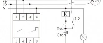
The protection equipment consists of a three-phase transformer, current-limiting resistors and a relay with two coils. One end of the primary winding is connected to the corresponding phase of the network, and the other is connected to pin 1 of the first winding of a two-winding relay.
The second pin is connected to ground. The secondary winding of the transformer (auxiliary current source) is connected to the second relay coil. They are connected back-to-back; the second winding has a larger induced current, but their difference (differential current) is not sufficient to open the contacts during normal network operation.
Description of the circuit operation
The protection device provides continuous monitoring of the network insulation resistance at voltages of 660/1140 V and automatically adapts to the specified voltages . After supplying the supply voltage to the device and three-phase mains voltage, the device automatically determines the voltage value and selects the response setting without operator intervention. The response setting set after switching on the three-phase voltage in the leakage relay mode, as well as in the preventive insulation monitoring mode, is stored in non-volatile memory until the next switching on of the supply and three-phase voltage.
In the mode of continuous monitoring of network insulation resistance, the protection device operates as follows. After voltage is applied to the transformer, a measuring current is generated, which flows through the filters, and after processing, it enters the input of the microcontroller, where it is measured. In this way, preliminary control of the network insulation resistance is carried out. When the network insulation resistance parameters are higher than the normalized ones, the microcontroller issues a signal, as a result of which the relay is charged and allows the switching of the power switching device that supplies voltage to the network. The elements of the measuring current circuit are continuously monitored by the microcontroller after the operating network voltage is applied to them. At the same time, self-testing of circuit elements occurs, the normal operation of which is indicated by a flashing LED. If the device malfunctions or at least one of the elements fails, the LED stops blinking, and the executive relay blocks the process of turning on the power circuit breaker.
After applying power voltage to the protection device, the voltage value is measured, the device response setting is selected, and the integrity of the measuring current and voltage circuits is monitored. As the network insulation resistance decreases, the measuring current increases, and if it exceeds a threshold value, the microcontroller issues a command through a relay to turn off the power switching device.
In this case, the date and time of the event, the nature of the event (emergency shutdown or shutdown as a result of testing), and the name of the damaged network phase are stored and recorded in non-volatile memory (EEPROM). When checking the operation of the device, the operation time is also recorded in the non-volatile memory (its own time, the time of shunting the damaged phase to the ground and the total operation time together with the circuit breaker). The specified information can be transmitted to the dispatcher via a communication line through the information block, or taken by operational personnel when investigating accidents using a specialized stand.
The kiloohmmeter is one of the elements of the measuring current circuit, therefore, if an information block is used instead, it is necessary to install a jumper between pins 1 and 9 of connector X1.
During the measurement process, the circuit of the flow of the measuring current, its magnitude, as well as the presence, the magnitude of the network neutral bias voltage and the phase relationships between the phase voltages and the network neutral bias voltage by the microcontroller are simultaneously continuously monitored. If they deviate from the specified reference values, the device also issues a command to turn off the power switching device. When a leak occurs in the network, based on a set of specified signs, the microcontroller determines the damaged phase of the network. After issuing a command to turn off the power switching device, a command is issued to operate one of the executive shunt relays, which connects one corresponding 100 Ohm resistor in parallel to the leak, and thereby greatly reduces the current flowing through the leak. The response setting of the faulty phase detector is a multifactorial dependence on the parameters of insulation resistance and network capacitance, is calculated and set automatically, and is not adjustable. The activation setting value of the device for detecting a damaged phase and the response time of the executive part of the circuit are selected from the conditions necessary to ensure that the amount of electricity flowing through the human body when touching a network phase is limited to no more than 50 mA•s.
After disconnecting the power switching device RUNN of the transformer substation, the protection device again switches to the operating mode of preliminary control of network insulation. When ordering, the device circuit can be made with blocking of the executive relay. With this design, after disconnecting the switching device, the executive relay is not restored and blocks the supply of voltage to the network until the “Alarm Reset” button is pressed or the supply voltage of the protection device is removed and reapplied.
The device monitors the presence of voltage in all three phases, as well as the asymmetry of the network voltage of no more than 15%. In the event of a break in one of the phases or asymmetry, the device issues a command to turn off the switching device through the executive relay, and the second line of the LCD indicates the missing phase, for example: “Failure of phase C.”
To check the operability of the protection device under operating conditions, the device is equipped with testing resistors that are connected via terminal K to the “Test” button of the transformer substation. In the leakage relay operating mode, using the “Check” button, an artificial current leakage to the ground is created through the indicated resistors, which leads to the activation of the protection device.
When using an information block with a display, it is possible to check the response time of the protection device together with the power switching device of the transformer substation. To do this, you need to connect a 1 kOhm resistor with a power of at least 50 W to the “Check” button in the RUNN of the transformer substation between terminal K and ground (). Close the switchgear cover, apply power to the device, turn on the power circuit breaker and press the “Check” button of the transformer substation. After this, the switching device will turn off and the display will display information about the device’s own response time, as well as the total response time together with the switching device. The obtained response time measurement results can serve as a test protocol for the protection device without additional bench tests during mandatory periodic checks.
Visual monitoring of the insulation state of the monitored network is carried out using a kiloohmmeter or an information block.
The protection device also has a light alarm with memory of the state of the device operation, made on an LED indicator, and a light indication connected to the contacts of the executive relay, indicating its state.
The state of the light indication about the activation of the protection device does not affect its performance. The light signaling about the activation of the protection device is returned to its original state using the “Indication reset” button of the transformer substation.
Depending on customer requirements, the electrical circuit of the device provides for a design with or without blocking the executive relay.
This design of the protection apparatus circuit allows you to:
- self-monitoring of elements and self-diagnosis of the state of the circuit with LED indication of the working condition of the device;
- the ability to check the device once a day;
- automatic adaptation to mains voltage and automatic selection of response settings without operator participation;
- blocking of the executive relay (version AZUR.4MK A) and alarm after activation of the protection device in emergency modes;
- the ability to build a power supply circuit without using zero protection in the device through the use of an intermediate output relay (if necessary);
- remote verification of operation in accordance with GOST R 52273-2004 “Mining leakage current protection devices for networks with voltages up to 1200 V”;
- the ability to check the operation time of the device together with a circuit breaker in a mine without the use of additional time control devices (when using the device in conjunction with an information block);
- registration and storage of test results and operations in emergency modes (black box function);
- digital indication and display on the LCD in real time of the state of the device, the value of the controlled leakage resistance, the network voltage, the current date and time, the value of the emergency network shutdown resistance, the damaged (shunted) phase;
- integration into the lower level of the automated process control system, incl. together with UTAS equipment;
- transferring data to the dispatcher about the current state of the device and network, about checks and emergency shutdowns (from the device’s archive log).
Trigger
The leakage resistance, if we consider the equivalent circuit, is connected in parallel with the device that controls the conductivity of the insulation. In the first winding, the current will be the largest with minimal insulation conductivity.
When conductivity increases above a threshold level, the operating current decreases so much that the relay contacts open. This leads to the application of a control action to the disconnecting winding of a powerful relay device.
It already disconnects the section of the network with insulation damage. Since the windings of a three-phase transformer are connected by a star, and the control signal to the two-winding relay comes from the center of the star, the protection equipment will operate in case of leaks in any line of the network.
Application of the UAKI-E device (380, 220, 127V)
The described device is actively used in systems that are powered from an isolated neutral, for example:
- excavator functional panels;
- transformer substations that are stationary during operation;
- drilling units of different sizes, etc.
It is known that the unit has an independent source that supplies supply and measuring voltage. This explains the possibility of searching for faulty zones when the input circuit breaker is turned off.
Share on social networks