Educational program KO. Lecture No. 4 Smoothing power filters.
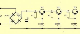
Power smoothing filters . Power smoothing filters are designed to reduce rectified voltage ripple. The principle of operation is simple - during the action of a half-wave voltage, the reactive elements (capacitor, inductor) are charged from a source - a diode rectifier, and discharged to the load during the absence or low amplitude voltage. Basic circuits of power smoothing filters
.
The simplest method of smoothing out ripples is to use a filter in the form of a capacitor of a sufficiently large capacity that shunts the load (load resistance). A capacitor smooths out ripples well if its capacitance is such that the condition is met: 1 / (ωС) << Rн
During the action of a sinusoidal signal, when the voltage on the rectifier diode is direct, a current passes through the diode, charging the capacitor to a voltage close to the maximum.
When the voltage at the output of the diode rectifier is less than the capacitor charge voltage, the capacitor is discharged through the load Rн
and creates a voltage across it, which gradually decreases as the capacitor is discharged through the load.
In each subsequent half-cycle, the capacitor is recharged and its voltage increases again. The greater the capacitance C
and the load resistance
Rн
, the slower the capacitor discharges, the less ripple and the closer the average value of the output voltage
Uav
to the maximum value of the sinusoid
Umax
.
If the load is turned off altogether, then in idle mode the capacitor will receive a constant voltage equal to Umax
, without any ripple.
The operation of the simplest smoothing filter on a capacitor in the circuit of a half-wave rectifier is illustrated by drawings and diagrams: The voltage at the output of the rectifier without a smoothing capacitor is shown in red, and in blue when it is present.
If the ripples should be small, or the load resistance Rн
is small, then an excessively large capacitance of the capacitor is required, i.e. It is practically impossible to smooth out ripples with a single capacitor. You have to use a more complex anti-aliasing filter.
The operation of a smoothing L-shaped filter on a capacitor and inductor in the circuit of a full-wave bridge rectifier is illustrated by drawings and diagrams: As in the example with a half-wave rectifier, the voltage at the output of the rectifier without smoothing elements (capacitor and inductor) is shown in red, and in blue if they are present .
It logically follows that the greater the capacitance and inductance of the filter, and the more reactive elements it contains (the more complex the filter), the lower the ripple factor of such a rectifier.
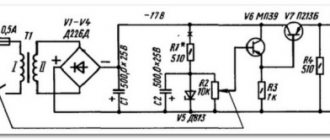
Electrolytic capacitors are used as smoothing capacitors. The larger the capacity, the better. In addition, for reliability, capacitors must be designed for a voltage one and a half to two times higher than the output voltage of the diode bridge. Determining the output voltage of the rectifier and choosing a smoothing filter for the secondary power supply
To what is described in the article, you should add important information used to design DC power sources (units):
1.
Any pn junction, any semiconductor device, including a diode, has a characteristic - voltage drop across the junction. This voltage is usually indicated in reference books. For germanium diodes it can be from 0.3 volts to 0.5 volts, and for silicon diodes it can be from 0.6 volts to 1.5 volts.
This means that if we take a transformer with an output voltage of 6.3 volts, rectify it with a single-phase bipolar bridge rectifier (diode bridge) in which, according to the reference book, 1 volt drops on each diode (Upr. = 1 V), then at the output of the rectifier we we get only 4.3 volts. A voltage of 2 volts is “lost” on 2 diodes along the path of current. Beginning radio amateurs usually do not take this into account, which is why they are perplexed why the output voltage is low.
2.
Alternating electric current is measured by instruments, which, as a rule, show its average value, not the maximum. The maximum value of an alternating voltage is the value of the electrical voltage corresponding to its maximum sinusoidal value.
The average voltage value at the output of a half-wave rectifier corresponds to the value: Uav = Umax / π = 0.318 * Umax
The average voltage value at the output of a full-wave rectifier corresponds to the value: Uav = 2 Umax / π = 0.636 * Umax
The average voltage value - 0.636, due to the design features of the measuring instruments, is rounded and taken equal to 0.7.
3.
Based on the above, we can draw a conclusion that is valid when the load on the power supply is small.
Pay attention to the pictures below. Output voltage of rectifiers with a power filter: a) with a large load: b) with a small load: These figures explain that at a low load, the output voltage of a rectifier with a power filter is equal to the maximum amplitude of the sinusoid arriving at the rectifier, minus the voltage drop across the diodes. An example of determining the output voltage and selecting a smoothing capacitor for a secondary power source
Consider the case with an average alternating voltage at the transformer output, measured with a multimeter equal to
6.3 volts
, and a load (load resistance) equal to
200 Ohms
.
The output voltage from the bridge rectifier will be determined as follows:
— maximum voltage at the transformer output:
Umax = Umeas / 0.7 = 6.3V / 0.7 = 9 volts
— maximum output voltage at the rectifier output:
Uout. = Umax – UVD1 – UVD2 = 9 – 1 – 1 = 7 volts
— the capacity of the smoothing capacitor is selected from the condition:
1 / (2*π*f*С) << Rн
, from where
1 / (2*π*f *Rн) << С
- let’s substitute the data:
1/(2*3.14*50*200) = 1.59*10-5 (Farad) = 15.9 µF
- taking into account the condition under which the capacitance of the capacitor should be much greater than that obtained according to the given condition, we select a capacitor with a capacity more than five times the calculated value - 100 μF * 16 volts
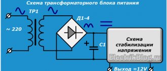
. A circuit consisting of a transformer, rectifier and smoothing filter is a source of unstabilized power. From such sources you can power any devices that consume low current and are not critical to the presence of ripples and instability of the supply voltage. For maximum suppression of ripple and stabilization of the supply voltage, voltage stabilizers are used.
The simplest LC filter
The simplest LC filter is an oscillating circuit, turned on as shown in Fig. 1. The input alternating voltage is supplied to the circuit through resistor R1, and the output voltage is removed from the circuit itself.
Rice. 1. LC filter circuit.
In general, this is very similar to a voltage divider with two resistors, but instead of one of the resistors there is a circuit. In essence, this is how it is.
At the resonant frequency, the reactance of the circuit increases greatly, which means that the division coefficient of such a divider decreases.
This circuit (Fig. 1) acts as a narrow-band bandpass filter, the central frequency of which can be calculated using the well-known formula:
, where frequency is in Hz, inductance in H, capacitance in F.
Loop resistance at resonant frequency:
where p is the characteristic resistance equal to the reactance of the coil and capacitor. The p value can be calculated using the formula:
But calculating the quality factor Q is much more difficult. This value depends on the losses in the circuit. Since a capacitor usually introduces a minimum of losses, the quality factor of the circuit is most often almost equal to the quality factor of the inductance that is part of this circuit.
The resonant frequency and quality factor can be determined by measurements. You need to assemble a circuit according to Figure 2. This is almost the same circuit as in Figure 1.
An alternating voltage corresponding to the calculated value in frequency is supplied from the generator “G” to the circuit through resistance R1. By adjusting the generator, they find the frequency at which resonance occurs, that is, at which the alternating current voltmeter P1 shows the greatest value.
Rice. 2. Circuit for measuring resonant frequency and quality factor.
This frequency will be the real resonant frequency. It may differ from the calculated value due to errors in capacitance and inductance values. Ideally, it is equal to the calculated one.
At the resonance frequency, R1 and the resonant resistance of the circuit Ro form a voltage divider, so the output voltage Uout = Uin * Ro / (R1+Ro).
By measuring the input voltage Uin and output voltage Uout from this formula, you can find the resonant resistance of the circuit Ro, and then, knowing the value of the characteristic resistance, from the formula
you can find the quality factor Q from the formula Ro=pQ. Another parameter of the LC filter is the passband where is the deviation of the input voltage frequency from resonance in one direction or another, at which the output voltage corresponding to resonance (Uout) decreases to 0.7Uout . Knowing the value of the passband, you can find the quality factor using the formula Q = Fo/(2*deltaF).
Thus, it becomes clear that the passband of an LC filter primarily depends on the quality factor of the circuit. It should be taken into account that in this way it is not the circuit’s own quality factor that will be determined, but a smaller value due to the shunting effect of resistor R1.
The disadvantage of the filter in Figure 1 is that it is strongly influenced by the value of the output resistance of the input AC voltage source.
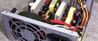
Design
The device resembles in appearance an extension cord with a switch off button, this is partly true, but in addition to the block with sockets and wires, filter elements are also located inside. They are precisely needed to protect against power surges and filter interference.
The simplest surge protector has a varistor inside. This is a semiconductor device that, when a certain voltage is exceeded, goes into a state of breakdown. It is used in surge protectors and power supplies to protect against voltage surges. Depending on the type of varistor, it can suppress pulses of different sizes.
This version of the varistor is the cheapest, since it does not filter anything other than voltage surges. Interference continues to leak into the network and interfere with surrounding and powered equipment.
L, LC and RLC filters are widely used to filter high-frequency interference; they are also installed in network filters and power supplies.
In addition to such options, there are also models where the power cord passes through a ferrite ring, or makes a couple of turns around it. In fact, this is another L (inductive) element, which is needed to filter the high-frequency component of the spectrum.
Schematic diagram
Figure 2 shows a typical power supply network filter circuit. It shows a three-wire (European) power supply network: “phase” - “zero” (“neutral”) - “ground”. Immediately at the filter input there is a varistor VR1.
Its task is to suppress high-voltage surges in the network. When such a surge appears, the electrical resistance of the varistor drops sharply, and it closes this interference through itself, not allowing it to pass further. Next, inductor T1 and capacitors C1, C2, C3 are included, forming an LC filter.
The resistance of the inductor increases with increasing frequency of the current, and the resistance of the capacitors decreases, so that all high-frequency noise is delayed or “drains” into the ground.
Interference can occur not only between the network wires (“phase” and “neutral”), they will be filtered by capacitor C3, but also between the “phase” and “ground”, and interference “neutral” - “ground” is also possible. To effectively suppress such interference, capacitors C1 and C2 are used.
Rice. 2. Typical power supply network filter circuit.
In the absence of ground, the common point of capacitors C1 and C2 “hangs” in the air, which leads to the creation by them and inductor T1 of a parasitic oscillatory circuit, which begins to emit a high-frequency electromagnetic field, becoming a source of potential danger for nearby radio equipment.
Rice. 3. Network filter circuit without grounded capacitors and connection to ground.
Therefore, in a two-wire network, filters are used without these capacitors and connection to the ground (Fig. 3). A typical amplitude-frequency response (AFC) of a network filter is shown in Fig. 4. From this graph it is clear that the higher the frequency of interference, the more effectively it is suppressed.
Rice. 4. Dependency graph.
It is worth dwelling on one feature of power filters. It will all be about the same “land”. There is a whole class of network filters in which the grounding wire has no connection with the internal circuit, except for the corresponding contacts of the Euro sockets themselves and the grounding contact of the Euro plug.
This achieves an important advantage: when operating from a grounded network, all filter sockets are grounded, as expected. But if there is no “ground” in the power outlet (a typical case of a domestic power supply network), all filter outlets are connected to each other via a grounding contact (naturally, the filter itself is not grounded). Why is it important?
Let's imagine, for example, a diagram of connecting various peripherals to a computer, shown in Fig. 5a (typical case - a printer, scanner, external audio amplifier, etc. are connected).
This is an ideal scheme: everything is connected to a grounded power supply network, the potentials of the device housings are the same (zero), since they are connected to ground. In the event of a breakdown or damage to the insulation of any of the devices, the “excess” voltage will go into the ground.
Rice. 5. Schemes for connecting various peripherals to a computer.
Now let's take a connection diagram for the case of a network without grounding (Fig. 5b). As you can see, there is no ground wire, and the only connection between the device cases is a low-current interface cable (more precisely, its braided shielding).
If there is a difference in potential between the computer case and the external device (and this happens all the time!), equalizing currents flowing from a higher potential to a lower one can easily “burn out” the input and output ports of the connected devices.
There are many such cases. The most common is the burnout of the input or output of the sound card if it is connected to an external signal source or to a sound amplifier.
To solve the problem, you need to connect these devices to a “European” extension cord, not even connected (for lack of it) to an external “ground” (Fig. 5c). Here, the electrical potentials of all devices are equalized, through currents will choose an easier path through the grounding contacts of Euro sockets, and nothing bad will happen.