The home handyman often encounters breakdowns of complex household appliances due to failures of its electrical circuit. It is not always possible to carry out such repairs immediately. Knowledge about switching power supplies and the operating principles of their components are often required.
Such workers are popular, always in demand, and deserve respect. However, not everything is as complicated in this matter as it seems at first glance.
I have identified 7 rules by which any UPS operates, and I tried to explain them in simple words for beginners. And judge for yourself what happened.
Power supplies are electrical devices that change the characteristics of industrial electricity to the level of parameters necessary for the operation of final mechanisms.
They are divided into transformer and pulse products.
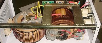
The power transformer lowers the input voltage and at the same time provides galvanic isolation between the electrical energy of the primary and secondary circuits.
Transformer modules spend a significant part of the power on electromagnetic transformations and heating, and have increased dimensions and weight.
Network filter circuits for pulsed and high-frequency interference: 4 types of designs
Rule No. 2: high-quality UPSs must have a reliable filter for high-frequency signals in the design of the unit .
It is important to understand that high frequency pulses play a dual role:
- V/h interference can come from the household network to the power supply;
- high-frequency current pulses are generated by the built-in converter and exit it into the home wiring.
Reasons for interference in a household network:
- aperiodic components of transient processes arising from switching powerful loads;
- operation of nearby devices with strong electromagnetic fields, for example, welding machines, powerful traction motors, power transformers;
- consequences of suppressed atmospheric discharge pulses and other factors, including the superposition of high-frequency harmonics.
Interference impairs the performance of electronic equipment, mobile devices and digital gadgets. They must be suppressed and blocked within the switching power supply design.
The filter is based on a choke made of two windings on one core.
Chokes can be made in different sizes, wound with thick or thin wire on large or small cores.
It is enough for a novice master to remember a simple rule: a filter with a large magnetic circuit inductor, an increased number of turns and a wire cross-section works better. (Principle: the more, the better.)
The inductor has inductive reactance, which sharply limits the high-frequency signal flowing through the phase or zero wire. At the same time, it does not have much effect on the current in the household network.
The operation of the inductor is effectively complemented by capacitive reactances.
The capacitors are selected in such a way that they short-circuit the interference signals weakened by the RF choke, directing them to ground potential.
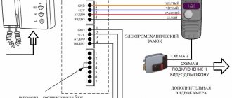
The principle of operation of the filter for high-frequency noise from penetration of input signals into the power supply is shown in the picture below.
Y capacitors are installed between the ground potentials with zero and phase. Their design feature is that in the event of a breakdown they are not capable of creating an internal short circuit and supplying 220 volts to the device body.
Between the phase and zero circuits, capacitors are placed that can withstand 400 volts, or better yet, 630. They are usually shaped like a parallelepiped.
However, you should be well aware that the UPSs in the voltage converter themselves correct the signal and interference practically does not interfere with them. Therefore, such a system is relevant for conventional analog blocks with output signal stabilization.
For a switching power supply, it is important to prevent RF interference from entering the household network. Another solution implements this feature.
As you can see, the principle is the same. It’s just that capacitive reactances are always located along the path of the interference behind the inductor.
The third circuit of the high-frequency filter is considered universal. She combined elements of the first two. The Y capacitors in it simply work on both sides of each inductor.
The most expensive and reliable devices use a complex filter with additionally connected chokes and capacitors.
I immediately show the arrangement of filters on all circuits of the power supply: input and output.
Please note that a ferrite filter, consisting of two detachable half-cylinders or made of a one-piece structure, can be additionally installed on the cable coming out of the UPS and connected to the electronic device.
An example of its use is a switching power supply for a laptop. This is already the fourth use of the filter.
Advantages and disadvantages of switching power supplies
Main advantages of UPS:
- Light weight and compact dimensions.
The reduction in device dimensions is due to the transition from the use of heavy power transformers. The UPS does not have linear control systems that require the installation of large cooling radiators. Increasing the frequency of processed signals also made it possible to reduce the size of capacitors. - High efficiency.
Low-frequency transformers are characterized by significant energy losses in the form of heat, which is generated as a result of electromagnetic transformations. In a UPS, maximum losses occur in the power switch cascade during transient processes, and the rest of the time the transistors are stable. Energy losses are kept to a minimum. The efficiency of the devices reaches 98%. - Wide range of input voltages.
The scope of application of the devices has been significantly expanded. Switching technologies allow the use of power supplies in networks with different electricity standards. - Built-in protection systems.
Most models have automatic protection against short-circuit currents, emergency load shutdown systems, etc. Protective devices are reliably integrated into the design of the units thanks to the use of miniature digital semiconductor modules. - Affordable price.
The UPS element base is constantly being unified. The cost of the main components of devices that are mass-produced on automatic machines is reduced. Additional cost reductions are achieved through the use of lower power semiconductors.
The disadvantages of the UPS are:
- Power restrictions.
There are contraindications for both high and low loads. If the current in the output circuit drops below a critical value, the unit begins to generate voltage with distorted characteristics, or the triggering circuit completely fails. - Presence of high frequency interference.
The blocks produce them in any design. High-frequency interference is transmitted into the environment, so it is necessary to additionally address the issue of suppressing it. For some types of sensitive digital equipment, the use of a UPS is not possible for this reason.
Mains voltage rectifier: the most popular design
Rule No. 3: after the output from the filter, the voltage is supplied to the rectifier circuit , which in the basic version consists of a diode bridge and an electrolytic capacitor.
During the electrical conversion, the shape of a sine wave, consisting of half-waves of opposite signs, first changes to a signal in a positive direction after the diode assembly, and then these pulsations are smoothed out to an almost constant amplitude value of 311 volts.
Such a network voltage rectifier is included in the operation of all power supplies.
Areas of application of switching power supplies
Small-sized UPSs based on integrated circuits are used in the design of chargers for electronic gadgets: tablets, phones, e-books. Elements of this type are also in demand in the production of televisions, amplifiers, medical devices, and low-voltage lighting installations.
Select and order power supplies in the catalog. We offer a wide range of models, competitive prices, and provide competent advice on the characteristics of devices. To contact specialists, call +375 (17) 513-99-92
or
+375 (17) 513-99-93
.
Pulse voltage converter: explanation in simple words with explanatory pictures
Rule No. 4: the rectified signal is subjected to pulse-width modulation on a power switch under the control of a PWM controller .
The power switch is made by the primary winding of a high-frequency transformer. For effective transformation of high-frequency pulses up to 100 kilohertz, the magnetic core structure is made of alsifer or ferrites.
The transformer winding receives signal pulses of several tens of kilohertz from the control circuits through an RF transistor.
Rectangular current pulses are supplied in time, alternating with pauses, and are designated by one (1) and zero (0).
The duration of the pulse or its width at each moment of low-frequency sinusoidal voltage corresponds to its amplitude: the larger it is, the wider the PWM. And vice versa.
The PWM controller monitors the value of the connected load at the output of the switching power supply. According to its value, it generates pulses that briefly open the power transistor.
If the power connected to the UPS begins to increase, then the control circuit increases the duration of the control pulses, and when it decreases, it decreases.
Due to the operation of this design, the voltage at the output of the unit is stabilized in a strictly defined range.
Types of switching power supplies
With galvanic isolation.
High-frequency signals are supplied to a transformer responsible for galvanic isolation of the circuits. Devices of this type have a more compact magnetic core and are characterized by increased efficiency. Most often, the transformer core is made of ferromagnets rather than electrical steels, which also makes it possible to reduce the size of the elements.
Without galvanic isolation.
There is no high-frequency isolation transformer in the pulse power supply circuit. The supply signal is fed to a low-pass filter.
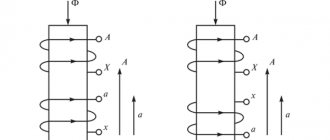
Pulse transformer: operating principle of one pulse in 2 cycles
Rule #5: The pulse transformer for the power supply transmits each PWM pulse due to two conversions of electromagnetic energy .
During the conversion of electrical energy to magnetic energy and back to electrical energy with reduced voltage, galvanic separation of the primary input circuits from the secondary output circuit is ensured.
Each PWM current pulse arriving when the power transistor is briefly opened flows through the closed circuit of the primary winding of the transformer.
Its energy is spent:
- first to magnetize the magnetic core;
- then to demagnetize it with current flowing through the secondary winding and additional charging of the capacitor.
According to this principle, each PWM pulse from the primary network recharges the storage capacitor.
UPS generators can operate using simple single-cycle or more complex push-pull construction technology.
Single-cycle switching power supply circuit: composition and principle of operation
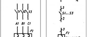
On side 220 there are: a fuse, a rectifying diode bridge, a smoothing capacitor, a bipolar transistor, chains of an oscillating circuit and collector current, as well as windings of a pulse transformer.
A single-cycle switching power supply circuit is created to transmit power of 10÷50 watts, no more. It is used to make chargers for mobile phones, tablets and other digital gadgets.
The rectifier diode D7 is used in the output circuit of the transformer. It can be turned on in the forward direction, as shown in the picture, or reverse, which is important to consider.
When connected directly, the pulse transformer accumulates inductive energy and transfers it to the output circuit to the connected load with a time delay.
If the diode is turned back on, then the transformation of energy from the primary circuit to the secondary circuit occurs during the off state of the transistor.
The single-cycle UPS circuit is characterized by its simplicity of design, but large voltage amplitudes applied to the turns of the primary winding of the pulse transformer.
Their protection is carried out by additional chains of resistors R2÷R4 and capacitors C2, C3.
Push-pull switching power supply circuit: 3 design options
Higher efficiency and reduced power losses are the undeniable advantages of these UPSs compared to single-cycle models.
The simplest version of the full-wave technique is shown in the picture.
If you additionally connect two diodes and one smoothing capacitor to it, then a bipolar circuit is obtained using the same transformer.
It is common in power amplifiers and operates on the flyback principle. In it, smaller currents flow through each capacitor, providing an increased service life of the capacitors during operation.
You can extend the service life of electrolytic capacitors in a UPS by replacing one high-power capacitor with several components. The current will be distributed throughout, which will cause less heating. And heat removal from each individual is better.
The forward-flow power supply circuit has a choke in its design, which performs the function of energy storage. To do this, two diodes direct incoming PWM pulses to its input in the same polarity.
The choke of these devices is made in large dimensions and is installed separately inside the UPS board. It complements the operation of the storage capacitor.
This is clearly visible in the upper form of the signal shown by the rectification oscillogram of the same block without and with a choke.
The forward circuit is used in high-power power supplies, for example, inside a computer.
It uses Schottky diodes to rectify the current. They are used due to:
- reduced voltage drop on direct connection;
- and increased speed when processing high-frequency pulses.
3 diagrams of power stages of push-pull UPSs
In order of complexity of their implementation, generators perform the following:
- half-bridge;
- pavement;
- or the push-pull principle of constructing the output stage.
Half-bridge switching power supply circuit: overview
Capacitors C1, C2 are assembled in series with a capacitive divider. A constant supply voltage is supplied to it and the collector-emitter transitions of transistors T1, T2.
The primary winding of transformer Tr2 is connected to the midpoint of the capacitive divider and transistors. The output voltage of the generator is removed from its secondary winding, which is proportional to the input signal TP1, transformed to the bases T1 and T2.
The half-bridge UPS circuit works for loads ranging from a few watts to kilowatts. Its disadvantage is the possibility of damage to elements during overloads, which requires the use of complex protections.
Bridge Switching Power Supply Circuit: Brief Explanation
Instead of the capacitive divider of the previous technology, transistors T3 and T4 work here. They open in pairs together with T1 and T2: (pair T1-T4), (pair T2-T3).
The voltage of the emitter-collector transitions for closed transistors is not higher than the value of the supply voltage, and on the winding w1 TP3 it increases to the value U supply. Due to this, the efficiency value increases.
The bridge circuit is difficult to set up due to difficulties in setting up the control circuits of transistors T1÷T4.
Push-pull circuit: important features
The primary winding of the output TP2 has a middle terminal, to which the positive potential of the power source is supplied, and its minus is applied to the middle point of the secondary winding T1.
During the passage of one half-cycle of oscillation, one of the transistors T1 or T2 and the corresponding part of the transformer half-winding operate.
Here the highest efficiency, low ripple and low interference are created. The amplitude value of the pulse voltage on any half of the winding w1 TP2 reaches the value U power.
The self-inductive emf is added to the collector-emitter junction voltage of each transistor, and it increases to 2U power supply. Therefore, T1 and T2 must be selected at 600÷700 volts.
The push-pull circuit of the key cascade is more popular. It is used in the most powerful converters.
Output Rectifier: The Most Popular Device
Rule #6: The signal coming from the UPS output is rectified and smoothed.
The simplest rectifier circuit, consisting of a diode and a storage capacitor, is shown in the picture below.
It can be modified by connecting additional capacitors, chokes, and filter elements.