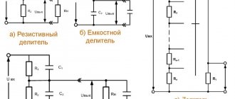
In electrical circuits, there is a constant need to stabilize certain parameters. For this purpose, special control and monitoring schemes are used. The accuracy of the stabilizing actions depends on the so-called standard, with which a specific parameter, for example, voltage, is compared. That is, when the parameter value is below the standard, the voltage stabilizer circuit will turn on the control and give a command to increase it. If necessary, the opposite action is performed - to reduce.
This operating principle underlies the automatic control of all known devices and systems. Voltage stabilizers operate in the same way, despite the variety of circuits and elements used to create them.
DIY 220V voltage stabilizer circuit
With ideal operation of electrical networks, the voltage value should change by no more than 10% of the nominal value, up or down. However, in practice, voltage drops reach much higher values, which has an extremely negative effect on electrical equipment, even to the point of failure.
Special stabilizing equipment will help protect against such troubles. However, due to its high cost, its use in domestic conditions is in many cases economically unprofitable. The best way out of the situation is a homemade 220V voltage stabilizer, the circuit of which is quite simple and inexpensive.
You can take an industrial design as a basis to find out what parts it consists of. Each stabilizer includes a transformer, resistors, capacitors, connecting and connecting cables. The simplest is considered an alternating voltage stabilizer, the circuit of which operates on the principle of a rheostat, increasing or decreasing the resistance in accordance with the current strength. Modern models additionally contain many other functions that protect household appliances from power surges.
Among homemade designs, triac devices are considered the most effective, so this model will be considered as an example. Current equalization with this device will be possible with an input voltage in the range of 130-270 volts. Before starting assembly, you must purchase a certain set of elements and components. It consists of a power supply, rectifier, controller, comparator, amplifiers, LEDs, autotransformer, load turn-on delay unit, optocoupler switches, fuse switch. The main working tools are tweezers and a soldering iron.
To assemble a 220-volt stabilizer, you will first need a printed circuit board measuring 11.5x9.0 cm, which must be prepared in advance. It is recommended to use foil fiberglass as a material. The layout of the parts is printed on a printer and transferred to the board using an iron.
Transformers for the circuit can be taken ready-made or assembled yourself. Finished transformers must be brand TPK-2-2 12V and connected in series to each other. To create your first transformer with your own hands, you will need a magnetic core with a cross-section of 1.87 cm² and 3 PEV-2 cables. The first cable is used in one winding. Its diameter will be 0.064 mm, and the number of turns will be 8669. The remaining wires are used in other windings. Their diameter will be already 0.185 mm, and the number of turns will be 522.
The second transformer is made on the basis of a toroidal magnetic core. Its winding is made of the same wire as in the first case, but the number of turns will be different and will be 455. In the second device, seven taps are made. The first three are made from wire with a diameter of 3 mm, and the rest from tires with a cross-section of 18 mm². This prevents the transformer from heating up during operation.
DIY linear voltage stabilizer
This article will discuss the circuit of a powerful linear voltage stabilizer, as well as step-by-step instructions for assembling it yourself. The stabilizer is assembled on an LM338 microcircuit, it provides a current of up to 5 A, has protection for output short circuit and overheating. The circuit is quite simple, so assembly should not be difficult.
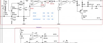
Linear voltage regulator circuit:
The LM338 chip has three pins - input (in), output (out) and control (adj). We apply a constant voltage of a certain value to the input, and remove a stabilized voltage from the output, the value of which is set by variable resistor P2. The output voltage is adjustable from 1.25 volts to the input value, with a deduction of 1.5 volts. Simply put, if the input is, for example, 24 volts, then the output voltage will vary from 1.25 to 22.5 volts.
You should not apply more than 30 volts to the input; the microcircuit may go into protection. The larger the capacitance of the capacitors at the input, the better, because they smooth out the ripples. The capacitance of the capacitors at the output of the microcircuit must be small, otherwise they will retain a charge for a long time and the output voltage will be regulated incorrectly. In this case, each electrolytic capacitor must be shunted with a film or ceramic capacitor with a low capacity (in the diagram these are C2 and C4).
When using a circuit with high currents, the microcircuit must be installed on a radiator, because it will dissipate the entire voltage drop. If the currents are small - up to 100 mA, a radiator is not required.
Voltage stabilizer assembly
The entire circuit is assembled on a small printed circuit board measuring 35 x 20 mm, which can be manufactured using the LUT method. The printed circuit board is completely ready for printing; there is no need to mirror it. Below are some photos of the process.
It is advisable to tin the tracks, this will reduce their resistance and protect them from oxidation. When the printed circuit board is ready, we begin to solder the parts. The microcircuit is soldered directly onto the board, with its back towards the edge. This arrangement allows you to mount the entire board with the microcircuit on the radiator.
The variable resistor is output from the board on two wires. You can use any variable resistor with a linear characteristic. In this case, its middle pin is connected to any of the outer ones, the resulting two contacts go to the board, as can be seen in the photo.
To connect the input and output wires, it is most convenient to use a connecting block. After assembly, it is necessary to check the correct installation.
Launch and testing of the linear stabilizer
When the board is assembled, you can proceed to testing. We connect a low-power load to the output, for example, an LED with a resistor and a voltmeter to monitor the voltage. We apply voltage to the input and monitor the voltmeter readings; the voltage should change when the knob is rotated from minimum to maximum. The LED will change brightness.
If the voltage is regulated, then the circuit is assembled correctly, you can place the microcircuit on a radiator and test it with a more powerful load. This adjustable stabilizer is ideal for use as a laboratory power supply. Particular attention should be paid to the choice of microcircuit, because it is very often counterfeited.
Fake microcircuits are cheap, but easily burn out at a current of 1 - 1.5 Amperes. The original ones are more expensive, but they honestly provide the declared current of up to 5 Amps. Happy assembly.
All parts can be purchased on Aliexpress using the links below:
Buy LM338 Buy 1N4007 Buy a set of resistors 300 pcs. Buy a set of capacitors 300 pcs. Set of electrolytic capacitors Buy set of potentiometers Buy terminal block
Photo of the linear stabilizer:
Video of the stabilizer in action:
Transistor voltage stabilizer circuits
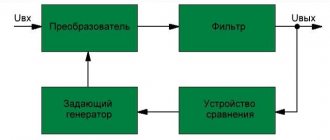
High-quality transformers used in the electrical circuit effectively cope even with large interference. They reliably protect household appliances and equipment installed in the house. A customized filtration system allows you to deal with any power surges. By controlling the voltage, current changes occur. The limiting frequency at the input increases, and at the output it decreases. Thus, the current in the circuit is converted in two stages.
First, a transistor with a filter is used at the input. Next, the diode bridge is switched on. To complete the current conversion, the circuit uses an amplifier, most often installed between resistors. Due to this, the required temperature level is maintained in the device.
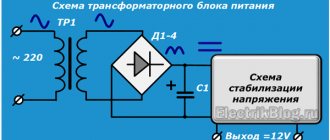
The rectification circuit operates as follows. Rectification of alternating voltage from the secondary winding of the transformer occurs using a diode bridge (VD1-VD4). Voltage smoothing is performed by capacitor C1, after which it enters the compensation stabilizer system. The action of resistor R1 sets the stabilizing current on the zener diode VD5. Resistor R2 is a load resistor. With the participation of capacitors C2 and C3, the supply voltage is filtered.
The value of the output voltage of the stabilizer will depend on the elements VD5 and R1, for the selection of which there is a special table. Transistor VT1 is installed on a radiator, the cooling surface area of which must be at least 50 cm2. The domestic transistor KT829A can be replaced with a foreign analogue BDX53 from Motorola. The remaining elements are marked: capacitors - K50-35, resistors - MLT-0.5.
Electronic voltage stabilizers
Electronic stabilization devices operate on the principle of stepwise voltage regulation through automatic switching of sections of the secondary winding of the transformer, which is carried out by power electronic switches controlled by the processor unit.
The absence of open switching eliminates the occurrence of sparks and oxidation of the current-carrying contacts of the stabilizer circuit when there is excess current at the input. In addition, equipment of this class provides low response time, is characterized by high structural reliability and completely silent operation.
You can assemble an electronic 220V voltage stabilizer with your own hands. The cost of such a device will be much lower than that produced at the factory, ensuring ease of maintenance. The main disadvantage of homemade solutions is their low reliability.
12V linear voltage regulator circuit
Linear stabilizers use KREN chips, as well as LM7805, LM1117 and LM350. It should be noted that the KREN symbol is not an abbreviation. This is an abbreviation of the full name of the stabilizer chip, designated as KR142EN5A. Other microcircuits of this type are designated in the same way. After the abbreviation, the name looks different - KREN142.
Linear stabilizers or DC voltage regulators are the most common. Their only drawback is the inability to operate at a voltage lower than the declared output voltage.
For example, if you need to get a voltage of 5 volts at the output of the LM7805, then the input voltage must be at least 6.5 volts. When less than 6.5V is applied to the input, a so-called voltage drop will occur, and the output will no longer have the declared 5 volts. In addition, linear stabilizers get very hot under load. This property underlies the principle of their operation. That is, voltage higher than stabilized is converted into heat. For example, when a voltage of 12V is applied to the input of the LM7805 microcircuit, then 7 of them will be used to heat the case, and only the necessary 5V will go to the consumer. During the transformation process, such strong heating occurs that this microcircuit will simply burn out in the absence of a cooling radiator.
Linear voltage stabilizers on transistors and op-amps
The main disadvantage of medium and high power linear stabilizers is their low efficiency. Moreover, the lower the output voltage of the power supply, the lower its efficiency becomes. This is explained by the fact that in the stabilization mode, the power transistor of the power source is usually connected in series with the load, and for normal operation of such a stabilizer, a collector-emitter voltage (11 kE) must be at least 3...5 V. For currents of more than 1 A, this gives significant power losses due to the release of thermal energy dissipated on the power transistor. Which leads to the need to increase the area of the heat sink or use a fan for forced cooling.
Widespread due to their low cost, integrated linear voltage stabilizers on microcircuits from the 142EN (5...14) series have the same drawback. Recently, imported microcircuits from the “LOW DROP” series (SD, DV, LT1083/1084/1085) have appeared on sale. These microcircuits can operate at a reduced voltage between input and output (up to 1...1.3 V) and provide a stabilized output voltage in the range of 1.25...30 V at a load current of 7.5/5/3 A, respectively. The closest domestic analogue in terms of parameters, type KR142EN22, has a maximum stabilization current of 5 A.
At the maximum output current, the stabilization mode is guaranteed by the manufacturer with an input-output voltage of at least 1.5 V. The microcircuits also have built-in protection against excess current in the load of the permissible value and thermal protection against overheating of the case.
These stabilizers provide output voltage instability of 0.05%/V, output voltage instability when the output current changes from 10 mA to a maximum value of no worse than 0.1%/V. A typical connection diagram for such voltage stabilizers is shown in Fig. 4.1.
Capacitors C2...C4 should be located close to the microcircuit and it is better if they are tantalum. The capacitance of capacitor C1 is selected from the condition of 2000 μF per 1 A of current. Microcircuits are available in three types of housing designs, shown in Fig. 4.2. The type of housing is specified by the last letters in the designation. More detailed information on these microcircuits is available in reference literature, for example J119.
It is economically feasible to use such voltage stabilizers when the load current is more than 1 A, as well as in case of lack of space in the design. Discrete elements can also be used as an economical power supply. Shown in Fig. 4.3 the circuit is designed for an output voltage of 5 V and a load current of up to 1 A. It ensures normal operation at a minimum voltage on the power transistor (0.7 ... 1.3 V). This is achieved by using a transistor (VT2) with a low voltage in the open state as a power regulator. This allows the stabilizer circuit to operate at lower input-output voltages.
The circuit has protection (trigger type) in case the current in the load exceeds the permissible value, as well as the voltage at the input of the stabilizer exceeds 10.8 V.
The protection unit is made on transistor VT1 and thyristor VS1. When the thyristor is triggered, it turns off the power to the DA1 microcircuit (pin 7 is short-circuited to the common wire). In this case, transistor VT3, and therefore VT2, will close and the output will have zero voltage. Returning the circuit to its original state after eliminating the cause that caused the overload can only be done by turning off and then turning on the power supply.
The SZ capacitor is usually not required - its task is to facilitate the startup of the circuit at the moment of switching on.
The circuit can only be returned to its original state after eliminating the cause that caused the overload by turning off and then turning on the power supply. The SZ capacitor is usually not required - its task is to facilitate the startup of the circuit at the moment of switching on. The topology of the printed circuit board for mounting the elements is shown in Fig. 4.4 (it contains one volume jumper). Transistor VT2 is installed on the radiator.
The following parts were used in manufacturing: adjusted resistor R8 type SPZ-19a, other resistors of any type; capacitors C1 - K50-29V for 16 V, C2...C5 - K10-17, C5 - K52-1 for 6.3 V. The circuit can be supplemented with an LED indicator for protection operation (HL1). To do this, you will need to install additional elements: diode VD3 and resistor R10, as shown in Fig. 4.5.
Literature: I.P. Shelestov - Useful diagrams for radio amateurs, book 3.
Adjustable voltage stabilizer circuit
Situations often arise when the voltage supplied by the stabilizer needs to be adjusted. The figure shows a simple circuit of an adjustable voltage and current stabilizer, which allows not only to stabilize, but also to regulate the voltage. It can be easily assembled even with only basic knowledge of electronics. For example, the input voltage is 50V, and the output is any value within 27 volts.
The main part of the stabilizer is the IRLZ24/32/44 field-effect transistor and other similar models. These transistors are equipped with three terminals - drain, source and gate. The structure of each of them consists of a dielectric metal (silicon dioxide) - a semiconductor. The housing contains a TL431 stabilizer chip, with the help of which the output electrical voltage is adjusted. The transistor itself can remain on the heatsink and be connected to the board by conductors.
This circuit can operate with input voltage in the range from 6 to 50V. The output voltage ranges from 3 to 27V and can be adjusted using a trimmer resistor. Depending on the design of the radiator, the output current reaches 10A. The capacity of smoothing capacitors C1 and C2 is 10-22 μF, and C3 is 4.7 μF. The circuit can work without them, but the quality of stabilization will be reduced. The electrolytic capacitors at the input and output are rated at approximately 50V. The power dissipated by such a stabilizer does not exceed 50 W.
Disadvantages of linear voltage regulators
A serious disadvantage of linear regulators is their low efficiency in many applications. The transistor inside the stabilizer, which is connected between the input and output terminals, acts as a variable series resistance; Thus, the high difference between input and output voltages combined with high load current results in significant power dissipation. The current required to operate the regulator's internal circuitry, indicated in the diagram by IGND, also contributes to the resulting power dissipation.
Perhaps the most likely failure mode in linear regulator circuits is due to thermal factors, not just electrical factors. The power dissipated by the regulator IC will cause the components to rise in temperature, and without adequate paths to conduct heat away from the regulator, temperatures can eventually become high enough to seriously degrade its performance or cause it to shut down if it overheats. This important topic is covered in the article on Thermal Design for Linear Regulators.
Triac voltage stabilizer circuit 220V
Triac stabilizers work in a similar way to relay devices. A significant difference is the presence of a unit that switches the transformer windings. Instead of relays, powerful triacs are used, operating under the control of controllers.
Control of the windings using triacs is non-contact, so there are no characteristic clicks when switching. Copper wire is used to wind the autotransformer. Triac stabilizers can operate at low voltage from 90 volts and high voltage up to 300 volts. Voltage regulation is carried out with an accuracy of up to 2%, which is why the lamps do not blink at all. However, during switching, a self-induced emf occurs, as in relay devices.
Triac switches are highly sensitive to overloads, and therefore they must have a power reserve. This type of stabilizer has a very complex temperature regime. Therefore, triacs are installed on radiators with forced fan cooling. The DIY 220V thyristor voltage stabilizer circuit works in exactly the same way.
There are devices with increased accuracy that operate on a two-stage system. The first stage performs a rough adjustment of the output voltage, while the second stage carries out this process much more precisely. Thus, control of two stages is performed using one controller, which actually means the presence of two stabilizers in a single housing. Both stages have windings wound in a common transformer. With 12 switches, these two stages allow you to adjust the output voltage in 36 levels, which ensures its high accuracy.
How does a linear voltage regulator work?
Linear voltage regulators, also called LDO (low-dropout linear regulator) or low-dropout linear regulators, use a transistor controlled by a negative feedback circuit to create a specified output voltage that remains stable despite changes in load current and input voltage.
A basic linear regulator with a fixed output voltage is a three-terminal device, as shown in the diagram above. Some linear regulators allow you to regulate the output voltage using an external resistor.
Voltage stabilizer with current protection circuit
These devices provide power primarily for low-voltage devices. This current and voltage stabilizer circuit is distinguished by its simple design, accessible element base, and the ability to smoothly adjust not only the output voltage, but also the current at which the protection is triggered. The basis of the circuit is a parallel regulator or adjustable zener diode, as well as a high-power bipolar transistor. Using a so-called measuring resistor, the current consumed by the load is monitored.
Sometimes a short circuit occurs at the output of the stabilizer or the load current exceeds the set value. In this case, the voltage across resistor R2 drops, and transistor VT2 opens. There is also a simultaneous opening of transistor VT3, which shunts the reference voltage source. As a result, the output voltage is reduced to almost zero level, and the control transistor is protected from current overloads. In order to set the exact threshold for current protection, a trimming resistor R3 is used, connected in parallel with resistor R2. The red color of LED1 indicates that the protection has tripped, and the green LED2 indicates the output voltage.
After correctly assembled, the circuits of powerful voltage stabilizers are immediately put into operation; you just need to set the required output voltage value. After loading the device, the rheostat sets the current at which the protection is triggered. If the protection should operate at a lower current, for this it is necessary to increase the value of resistor R2. For example, with R2 equal to 0.1 Ohm, the minimum protection current will be about 8A. If, on the contrary, you need to increase the load current, you should connect two or more transistors in parallel, the emitters of which have equalizing resistors.
Voltage stabilizer using a transistor
What is a voltage stabilizer
If you supplement the design with a zener diode with an emitter follower, you will get a parametric stabilizer based on a transistor and a zener diode with better parameters in terms of load current.
In this circuit, the load voltage is determined by the difference between the drop across the zener diode and the base-emitter junction. Stabilization occurs because the potential difference of the base-emitter junction weakly depends on the emitter current.
Turning on the amplification element allows you to increase the load current by a factor of Bst, where Bst is the static transfer coefficient. Using a composite element (Darlington circuit), the permissible load current can be further increased to several amperes.
Darlington circuit
The parametric voltage stabilizer circuit on a transistor has disadvantages. Some voltage instability at the base-emitter junction worsens the stabilization coefficient of the design as a whole. Reducing the load power below a certain minimum causes the output voltage to increase (for silicon components by 0.6 Volts as the base current becomes zero).
Relay voltage stabilizer circuit 220
With the help of a relay stabilizer, reliable protection of instruments and other electronic devices is provided, for which the standard voltage level is 220V. This voltage stabilizer is 220V, the circuit of which is known to everyone. It is widely popular due to the simplicity of its design.
In order to properly operate this device, it is necessary to study its design and operating principle. Each relay stabilizer consists of an automatic transformer and an electronic circuit that controls its operation. In addition, there is a relay housed in a durable housing. This device belongs to the voltage booster category, that is, it only adds current in the event of low voltage.
Adding the required number of volts is done by connecting the transformer winding. Usually 4 windings are used for operation. If the current in the electrical network is too high, the transformer automatically reduces the voltage to the desired value. The design can be supplemented with other elements, for example, a display.
Thus, the relay voltage stabilizer has a very simple operating principle. The current is measured by an electronic circuit, then, after receiving the results, it is compared with the output current. The resulting voltage difference is regulated independently by selecting the required winding. Next, the relay is connected and the voltage reaches the required level.
Servo stabilizers
The servo-type voltage stabilizer circuit includes:
- Overload protection unit;
- Autotransformer;
- Servomotor with gearbox;
- Control block
Servo-drive voltage stabilizers equalize the output current through a servo drive, which drives the switching contacts - graphite brushes. The movement of the latter to the desired position of the transformer winding is carried out smoothly without phase interruption and distortion of the output voltage sinusoid. When the input current surges or sags within 10 V, the control unit issues a command to the servomotor, which moves the switching contacts until the required output reaches 220 V.
The servo-type adjustable voltage stabilizer circuit includes moving elements, which reduces its reliability and durability. In addition, devices of this class support a fairly narrow range of input voltage (150-260 V) and permissible load (within 250-500 W). At the same time, they operate almost silently and provide an error in equalizing current parameters of no more than 2-3%.
Operating principle of a relay voltage stabilizer
First of all, the incoming voltage is measured in the stabilizer, then, depending on the results obtained, a signal is sent from the control board to open one or another relay, respectively, the electric current from one of the taps of the autotransformer, reduced or increased to the desired value, is supplied to the terminals of the stabilizer , to the consumer.
To fully understand the principle of operation of a relay stabilizer, you should definitely know about the operation of the autotransformer and its structure, if you have not yet read our article about it - now is the time to do so by following the link.
As an example of how a stabilizer works, let's assume that each tap of the autotransformer gives +/- 15 Volts of voltage change, it works as follows:
— If the voltage in the network is 220V , it is immediately transmitted to the consumer, the transformation ratio is 1. Accordingly, in the range from 205V to 235V (220V +/-15V), the voltage to the output of the stabilizer will be transmitted without changes.
— As soon as the incoming voltage drops to a value less than 205 Volts , the first secondary winding of the autotransformer is activated, with a transformation ratio of 1.075, thereby again producing 220 V (205 * 1.075) at the output. At this moment, the relay responsible for this tap of the autotransformer closes, releasing current to the output contacts of the stabilizer, and all others open.
Further, until the voltage drops another 15V i.e. up to 190V (205V-15V), this secondary winding will continue to operate with the same transformation ratio, thus, if the network voltage drops to 196V (switching limit to the next mode), the output is 211V (196 * 1.075).
— When the incoming voltage drops below 190V , the next relay is triggered, and the previous one opens, thereby turning on the next secondary winding of the automatic transformer, with a transformation ratio of 1.15 and the output voltage again becomes 220V (196 * 1.15) and so on, every 15V the winding switches to, say, 145V - after which the stabilizer goes into protection.
- If, on the contrary, the voltage in the network increases above 235V , using the appropriate relay, the step-down secondary winding is activated, with a transformation ratio of 0.94, and again the voltage in the network is equalized to the required 220V (235 * 0.94).
I think that now the principle of operation of a relay stabilizer is clear to you, now let’s look at what strengths and weaknesses a stabilizer of this type has, and in what areas it is best used.
The best relay voltage stabilizers
Currently, there are quite a lot of players in the stabilizer market, large and small manufacturers, each with several lines of models, with different output power and functions, so it is not easy to name any specific successful products.
But of course, by studying the experience and reviews of our colleagues, suppliers and clients, we can identify several of the most optimal manufacturers in various categories of consumer properties, using the example of 5 kW - kVA models in particular:
ENTRY LEVEL
Of the most affordable, inexpensive , but at the same time quite high-quality relay voltage stabilizers, I advise you to take a closer look at the models of the following manufacturers: Resanta Quattro Elementi. These stabilizers are used especially successfully in the country house, garden plot or garage, as well as when powering household appliances or power tools.
Stabilizers from these manufacturers are often installed in apartments and cottages, boiler rooms and other places where reliability is important, both in stabilizing and protecting electrical appliances from the negative effects of poor-quality electrical current parameters.
Inexpensive and high-quality relay stabilizer RESANTA ACH-5000/1-C (~ 5400 rubles)
Quattro elementi stabilia 5000 - Another affordable relay stabilizer with good reviews (~6000 rubles)
MORE..
PRICE QUALITY
In terms of price/quality ratio , with an emphasis on reliability, quality and functions, such as a wider range of stabilization, additional protection and filters, the most interesting manufacturers of relay stabilizers, according to a large number of consumers, are: Energy and Rucelf of the following models:
One of the most successful models of relay stabilizers, combines affordable cost and high reliability RUCELF StAR-5000 (6500 rubles)
Energy ACH 5000 is a Russian-made relay stabilizer, in a compact, portable design, 7 stages of stabilization. (~7000 rubles)
ADVANCED MODELS
The most expensive and advanced relay stabilizers, with the maximum number of options, a high degree of stabilization and other high-level characteristics, which are designed for installation in more critical places that are demanding in terms of quality, reliability and accuracy of voltage parameters, for example, in production, in cafes, shops and etc. produced by manufacturers: Lider, Energy, Uniel
Energy Voltron 5000 is a professional high-quality relay voltage stabilizer, with very good characteristics and additional functions. (~9000 rubles)
Uniel-rs-1-5000ls - relay stabilizer with the widest stabilization range, high response speed, its characteristics are compared with ... (~ 12,000 rubles)
If you know other worthy manufacturers or successful models of relay stabilizers, be sure to write in the comments to the article. In addition, ask questions, and if you have comments or criticism, express them.
If you think that a relay device is not what you are looking for, be sure to study the features of stabilizers of other types and read reviews of models for different typical cases, all this and much more awaits you in upcoming articles, follow the release of new materials, subscribe to our VKontakte group.
Relay voltage stabilizer device
The heart of any relay stabilizer is an ordinary autotransformer; we have already written about it in some detail; by clicking on the link you can find out what it is and how it works.
Now it’s worth saying that the autotransformer has several taps - taps from the winding, each of which forms a secondary winding, with a different transformation ratio of the incoming voltage. In this way, the voltage can increase or decrease, and we will look at how this works below.
In addition to the automatic transformer, another important part of any relay stabilizer is the control board. It contains a number of components and solutions, in particular a voltmeter that measures the incoming voltage and control circuits that are responsible for switching the stabilizer modes.
Power relays directly switch the corresponding taps of the secondary winding of the autotransformer with the output contacts of the stabilizer.
A relay is a kind of circuit breaker; based on a signal, it mechanically closes or opens an electrical circuit. Depending on the model of the device, the number of such relays - stabilization stages, as well as their type, may vary.
In addition to the above, any electronic relay stabilizer also has fuses, indicators and other components on board, but we will not describe them; their type and quantity can vary greatly depending on the model of a particular device.
Now, to better understand how it works, let's look at its diagram.