Stabilizer connection
Connection diagram for a single-phase electricity stabilizer in a network with a voltage of 220 Volts
To comply with this rule, you need to turn off the input circuit breaker, which is located in the distribution panel, then you need to check again whether the power is turned off. For these purposes, use a special index.
Basically, the stabilizer turns on immediately after voltage is applied. The electricity stabilizer has a sequential connection type. A small cheat sheet for you can be the connection diagram of the stabilizer, printed on its body by the manufacturer.
A single-phase stabilizer has three contacts that are involved in the connection process:
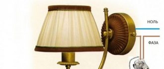
- A phase wire is taken from the input circuit breaker and connected to the “input” point in the wire connection block of the stabilizer;
- Connect the phase wire responsible for load distribution to the “output”;
- Last step. Find the neutral contact of the stabilizer and connect it to the neutral wire of the network, avoiding a break.
The neutral wire must first be connected to the stabilizer, then to the common neutral wire of the network.
What to do if there are 4 contacts for connection on the stabilizer body
It happens that when examining an electricity stabilizer, you can immediately observe 4 contacts for connection. It looks like this:
- phase - “entrance”;
- 0 – “input”;
- phase – “exit”;
- 0 – “exit”.
If there is such a circuit in the voltage stabilizer, the connection to the network occurs as follows:
The neutral and phase wires of the electrical panel are connected to the corresponding contact, called “input” on the body of the protective device. In this case, the neutral and phase wires responsible for the load are connected to contacts marked “output”.
When the installation process is complete, double-check that you have connected all the wires correctly. Before turning on the device for the first time, you must turn off the power to all electrical appliances and remove all plugs from the sockets.
When the stabilizer turns on, carefully monitor its proper functioning. It should work quietly without any extraneous noise in the form of crackling, etc.
Also, voltage stabilizers with low power (P<1.5 kW) can be found on sale. They are produced as a complete independent unit, complete with a cord for connecting to the network with a standard plug. There are several sockets on the surface of the device body.
Any electrical device whose operation you want to protect from risk is connected to the voltage stabilizer through such an outlet. Based on this, we can conclude that devices that protect electricity and devices operating on its basis are a kind of additional link between the load and the electrical network, which provide reliable protection against voltage surges and network overload.
Why do you need a voltage stabilizer?
The voltage stabilizer serves to equalize the input voltage. Also, the stabilizer serves as protection against short circuits and power overloads. In simple words, if you have bad voltage at home, it is low or fluctuates a lot, then you need a stabilizer.
Today, there are various voltage stabilizers: relay, servo, triac, and others. We will not consider their design in detail, since this is the topic of more than one article.
It’s better to consider why the voltage stabilizer turns off, because this is one of the most common problems when operating this equipment.
Why does the voltage stabilizer keep turning off?
It happens that after purchasing and installing a voltage stabilizer, it begins to turn off and goes into a delay. The stabilizer delay is a certain time, usually 5-6 seconds, during which the automation checks the incoming voltage, after which it commands the stabilizer to turn on.
So, frequent shutdowns of the voltage stabilizer are most often associated with:
- With insufficient power input voltage, the voltage is very low;
- With weak voltage stabilizer power;
- Due to a short circuit in the electrical network;
- Due to high inrush currents;
- Due to overheating of the stabilizer.
Let's look at each of the above problems in order to understand what to do if the voltage stabilizer turns off.
To increase the life of transistors and servomotor
My reader and subscriber of the SamElectric.ru group Andrey Altukhov shared his circuit, which avoids overheating of transistors and increases the life of the motor due to the fact that the stabilizer does not respond to small (2-3 V) changes in the input voltage. The diagram and description are given “as is”; whoever repeats the modification - write in the comments!
Here's what Andrey writes:
The comments offered options on how to save the board and electric motor from premature failure. After the servo motor died twice in 2 years from overheating of the brushes and the control board in the area of the power transistors turned black, I decided to delve deeper into the issue. I played around with the gain factors of the op-amp, twisted it back and forth, but still the linear mode of operation did not go away.
I thought I could quickly solve the problem by installing a zener diode or a diode at worst, but the voltage levels are too low to make any difference. It is also possible to build something with a dead zone on transistors, but this is all a grandiose stucco on the board. Ideas swarmed in my head to insert a second op-amp and connect it to the break in the control circuit.
And then my father, looking over his shoulder, discovered in the diagram a completely unused (at least in the single-phase version) operational amplifier, already soldered on the board on legs 12, 13, 14 with output to pin 4XT2, which was simply hanging in the air. And then there were estimates of gain factors and feedback. As a result, this scheme was born. (picture based on one taken from the article).
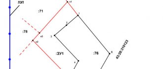
Stabilizer circuit with response threshold
The threshold element is two back-to-back diodes connected in parallel. resistors R101 and R102 regulate the feedback and ultimately give the width of the dead zone. I settled on the 10k and 2.2k ratings which gives about 3V AC insensitivity. As soon as the voltage in the network changes to a larger value, one of the diodes opens and the electric motor is supplied not with a gradually increasing voltage, but immediately with a threshold, allowing the engine to immediately take a step. In addition, correction of the output voltage with a trimmer was required to set the output voltage. Well, with the second file I’m attaching what the printed circuit board looks like after modification.
Stabilizer printed circuit board after modification
Yes, in the original circuit, instead of a motor, I connected a small light bulb and a voltmeter. The tension gradually increases in either direction. In my circuit, the motor turns on when there is already a more serious voltage deviation. Moreover, if the voltage suddenly jumps in either direction, there will be no delays in operation.
Refinement affects accuracy, but in real life it does not matter much. The output voltage in my case has the right to vary +- 3 volts from the set nominal value. This is an inevitable price to pay for less nervousness of the servo. You can increase the gain of the first op-amp (blue text in the diagram) and get +- 1.5 volts.
There is one more moment. All experiments were carried out on a stabilizer in which the motor was replaced with a more expensive version with graphite brushes. It was not possible to check how it will spin with a standard motor.
What to do if the stabilizer turns off
Each voltage stabilizer is designed for a specific operating voltage range. In other words, the stabilizer will turn off if the voltage in the electrical network becomes higher or lower than the parameters specified in its automation. The lower threshold for turning off the stabilizer can be different - 90 or 140 Volts, it all depends on the model and type of stabilizer. The same applies to the upper voltage threshold, usually 240 Volts.
Therefore, if your power supply voltage is too low, below 140 or 90 Volts, the stabilizer will turn off automatically. This problem can be solved either by replacing the voltage stabilizer with another one that will operate on very low voltage, or by writing a statement to the Distribution Zone. The fact is that a voltage of even 190 Volts, not to mention 140, is not the norm, and you can safely make your claims about this.
Causes of breakdowns
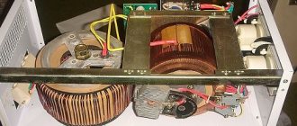
The main cause of malfunction of the Resanta 10000W voltage stabilizer is improper operation of the equipment. Quite often, overheating of rectifiers is observed when using equipment in a dusty room. Dirt settles inside the case, which impairs the cooling of the device, and problems arise with overvoltage of the power part and execution boards.
Also, the cause of breakdown of electrical rectifiers can be operation in conditions of high humidity. The contacts and boards begin to oxidize, the connection deteriorates, which ultimately leads to serious damage to the stabilizers - they can be restored by replacing the servo drive or power elements.
In the stabilizer operating instructions you can find all the recommendations for using the equipment, which will help prevent the occurrence of typical breakdowns and the need for expensive and complex equipment repairs.
In the Resanta line you can find both simple and inexpensive household models that are intended for indoor use, as well as specialized industrial installations that can be used in conditions of high humidity and dusty, contaminated workshops. By choosing the right stabilizer, you can guarantee trouble-free operation and no breakdowns even under increased load.
You might be interested in DIY power supply from an energy-saving lamp