The refrigerator is an example of a household appliance that no family can do without today. Like most complex electromechanical devices, refrigerators can fail at some point, after which you have to call in a repairman. However, there may be situations when a relatively simple malfunction can be diagnosed and fixed on your own.
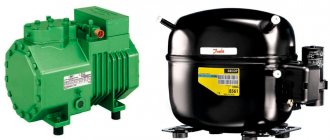
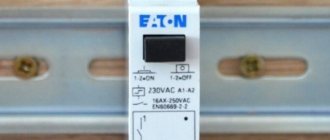
Modern refrigeration units are equipped with compressors with a single-phase motor, for the start of which a special starting relay (PR) is provided. When this unit fails for some reason, the compressor of the unit stops starting. In this review you can get acquainted with how PR works and what are the signs of its failure. Users who have a good understanding of the operation of the trigger circuit will be able to independently eliminate the malfunction.
Starting the engine
At their core, the drive motors used in compressors are single-phase asynchronous motors (IM) equipped with a starting winding. The basis of their design is a stationary stator with a set of coils and a rotating rotor. The moving part of the engine, or rotor, is a hollow cylinder made of aluminum (also called a “squirrel cage”).
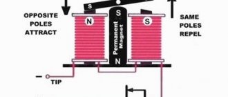
The stator of the motor unit contains a pair of working windings, one of which is the main winding, and the second serves as a starting winding. They are located in relation to one another at right angles, or are wound in opposite directions, forming a kind of “bifilar”. The current flowing through the main winding creates an electromagnetic field with a changing vector direction. When the rotor rotates, according to the law of electromagnetic induction, a resultant magnetic flux (EMF) is created in the motor. As a rule, it is enough to support its rotation due to the current flowing through the main coil.
If the rotor is stationary in the initial position (which is considered normal), then the resulting EMF approaches zero. In this case, to start the engine, additional force will be required to provide the required starting torque. For these purposes, a starting coil is needed.
For the motor to start and operate normally, the currents in the coils must be out of phase with one another. For this reason, its design includes an additional phase-shifting element (choke or capacitor). As soon as the engine develops the required speed, the need for a starting coil disappears.
Conclusion: To start the blood pressure normally, you need to use both coils at once (main and starting). On the other hand, for regular rotation of the rotor, only one is enough - the main one. For timely switching of these circuits, a starting relay is used, which is switched on directly in front of the compressor.
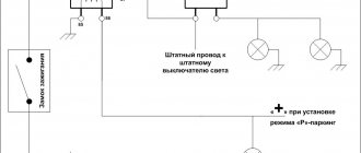
Connecting a compressor without a switch
Connecting a compressor to a system without a relay is carried out according to the diagram that we have given below.
Motor connection diagram without relay
You need to take a conductor with two wires on one side and a plug on the other side. One contact should be connected to the main point, and the other to the working winding. Now these contacts should be connected and the plug plugged into the socket. In this case, a working refrigerator will function.
Video - Connecting a compressor without a switch
Operating principle of PR
Despite the variety of models and electrical circuits of modern refrigerators, the principle of operation of the PR is the same for all of them. After becoming familiar with the operating features of this element in one of the models, you will be able to independently diagnose and repair it.
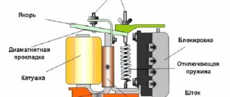
Device diagram and connection to the compressor
In the electrical diagram of a relay device, the input and output circuits are first distinguished. It clearly shows two power wires and three wires going to the compressor. One of them (zero power bus) is common for input and output. The second (phase) core inside the relay is split into two chains, one of which supplies the phase to the working coil. The other tap is designed to supply mains power to the switching contact of the starting circuit.
If the relay itself does not have contact markings, it is easy to make a mistake when connecting it to the compressor. The method proposed by some experts for identifying windings by measuring their resistance is very often not applicable. This is explained by the fact that for some compressor models their resistances are almost the same.
That is why, to clarify the purpose of the contact pads, you will need to find a passport with a diagram on which they are indicated by the corresponding icons (indicating the purpose). If there are markings, please note that for some models of units the symbols are interpreted as follows:
- “S” is the contact of the wire going to the starting winding.
- “R” – the same, but for connecting to the working coil.
- “C” is the common (or zero bus).
In addition, different relay models differ in the method of mounting on the elements of the refrigerator frame (compressor). Each of them has special current characteristics, which forces, when replacing, to choose samples with similar parameters.
Switching circuits using the electric method
E/m type relays are activated by the flow of current through a series-connected starting winding, which leads to the closure of its working contacts. Since when the compressor starts, a significant current flows through it, a magnetic field is formed that is sufficient to close the contact of the starting coil. Immediately after this, the rotor begins to accelerate.
When a certain speed is reached, this current decreases and the magnetic field strength decreases. Due to the elasticity of the return spring, the relay core moves back, opening the power circuit of the starting coil. After this, the compressor engine switches to the mode of ensuring constant rotor rotation. In this case, current flows only through the main winding. Subsequently, the PR switches only after the rotor stops rotating.
Current regulation with a posistor
Some refrigerators use an electronic device as a switching element - a posistor, which is a thermal modification of a resistor. At low temperatures its resistance is low, and with its increase it increases sharply (which is equivalent to opening the circuit). This element is installed in a chain through which current is supplied to the starting coil.
The principle of its operation can be described as follows:
- At normal temperature (at the initial stage of refrigerator operation), the current through the posistor is sufficient to start the compressor motor.
- As the circuit operates, this element heats up due to the flow of current, and after reaching a fixed temperature, its high resistance opens the circuit (de-energizes the starting coil).
- The compressor motor then runs on only one working winding.
The posistor cools down only after the voltage is removed from the compressor, and is triggered again the next time the engine is turned on.
Current protection device
Asynchronous motors provide several types of protection against current consumption exceeding a specified value. This occurs during a short circuit in the operating circuits or when the components overheat due to fan failure (thermal protection is triggered). At the same time, a situation cannot be excluded when the engine operates for some time (on the order of several seconds) in the mode of limiting currents that exceed the norm by 2-5 times. As a rule, this happens when the load on the shaft increases sharply due to the phenomenon of jamming.
At the same time, the current consumed from the network also increases, but its value does not reach the short-circuit values. As a result, the circuit breaker does not have time to turn off the power circuit. The thermal relay also does not work, since the temperature of its contact does not have time to change in such a short time. The surest way to protect the motor from overload in this case is to use a current protection device installed in the following places:
- In the internal cavity of the compressor.
- In a separate building.
- Inside the PR itself.
In the latter case, a device is obtained that combines the functions of connecting the starting circuit and current protection. Experts call it a start-up protection relay (PPR).
The operation of this device is based on 3 principles:
- as the current increases, conductive materials heat up;
- as a result, expansion of the metal is observed;
- For different types of metal materials, the expansion coefficient is different.
All these principles are satisfied by structures made in the form of bimetallic plates welded together with excellent CTE (coefficient of thermal expansion).
Due to the difference in these indicators, when heated by the current flowing through it, such a plate begins to bend; moreover, one of its ends remains in a fixed position. At the same time, the second one is slightly deflected and opens the working contact. Each type of bimetallic plate is designed for a certain current, so when replacing a PZR, you will need to make sure that it is compatible with a non-working device.
How to test the refrigerator start relay
It is not uncommon for a refrigerator to suddenly break down. The cause of the breakdown can be many factors. This includes a power surge, physical damage, and manufacturing defects. You need to know how you can diagnose a refrigerator relay for stability. You can do a short test yourself at home. Electrical measuring instruments must be available.
View » Malfunctions of the Bosch No Frost two-chamber refrigerator
First you need to find out whether the spare part is located correctly. The norm is strictly vertical. Then you need to remove the part, check its integrity and contacts. They may become acidic or dirty, then they should be carefully treated with fine sandpaper. Contact between terminals can be checked using a tester. It is better to remove noticed rust with a special solution. The presence of traces of burning means only one option - the part is faulty and must be replaced.
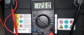
Using the “diagnosis” procedure, it is worth testing whether the voltage is correct for the compressor (you should use an ohmmeter or multimeter).
The parameters obtained as a result of the measurement are compared with those declared for this refrigerator model. If the actions do not lead to a positive result, you can call a specialist to your home. On site, a specialist with special knowledge and skills will be able to determine how much repairs cost, how to check the refrigerator start relay for functionality most effectively, and where else the breakdown may be located.
Where is the relay located
The initial installation location is determined by the manufacturer based on their size, type and model. You can see where it is and check the relay by removing the back panel of the refrigerator. In this case, be sure to follow electrical safety precautions.
Troubleshooting
Taking into account the fact that the number of elements in the relay is insignificant, their serviceability can be checked using the method of sequential elimination. To do this, just stock up on a flat-head screwdriver and a multimeter. During repairs, it is important to pay attention to the following points.
Purely structurally, e/m relays are devices with contacts that are open in the normal state. The posistor version of the switching device has contacts that are initially closed. In the first case, when the motor starts, no current flows through the starting circuit, but in the second case, vice versa.
If a compressor that is known to be working does not start, this means that voltage is not supplied to the starting coil. The reason in this case is as follows:
- Triggering of the current protection relay.
- A break in the circuit through which current should initially flow.
- PTC fault.
Let's look at each of these problems in more detail.
Malfunctions in the current protection relay (RZT)
In a situation where the refrigerator turns on for a while (5-20 seconds) and then turns off, this means that the relay switch has tripped.
The reasons for its disabling are listed below:
- operation is associated with damage to the working winding (the relay is triggered by overcurrent);
- the starting relay does not open the contacts in the starting circuit;
- The current relay is faulty and is triggered by minimal heating.
If, when testing with a multimeter, a break in the power supply circuit of the windings is detected, most likely the protection relay itself is faulty. This is usually caused by poor contact in the bimetallic strip. The easiest way out is to replace the damaged device with a new one.
Problems in the starting circuit
Faults of this type are detected using a conventional multimeter, with which you will need to test the following electrical circuits:
- If a break is detected in the area up to the working winding, it is necessary to check the serviceability of the PZR.
- In this case, special attention is paid to sticking or oxidation of its contacts.
- If there is no continuity in the area up to the start coil, in addition to an open circuit, malfunctions of the PZR or lack of contact in the connecting strips are possible.
In a device with an induction coil, to restore contact, you will have to manually lift the contact bar with the return spring.
PTC fault
To make sure the posistor is working, you will need to check its resistance in various states. To do this, wait until it has completely cooled down and test its circuit with a multimeter or similar device. If the tester shows a complete absence of current or a significant resistance value, the posistor should be replaced with a new sample.
To check the shutdown mode, you need to connect some load to the posistor (for example, a 100-watt incandescent lamp). To do this, you will need a plug with terminals connected to the input circuit of the device. The wires coming from the lamp are connected to a connector, the contacts of which are connected to the power supply zero and the phase end of the starting winding.
When turned on, current begins to flow throughout the protective circuit and through the lamp and it lights up. Since its value is significantly lower than when starting the engine, the protective element heats up for a very long time (for the selected lamp this period will be about 20-40 seconds).
If over time the incandescent light bulb goes out, then you can be sure that the element being tested is in good working order. If nothing happens and the circuit does not break over time, this means that the posistor is faulty. In this situation, the easiest way is to purchase a new device.
Problems with contacts
There are two known causes of the malfunction in question. This is the absence of current in the circuit with seemingly closed contacts and their sticking due to loss of elasticity of the plates. The first case is typical for a situation where the contact heels are heavily oxidized. The problem can be solved by cleaning them using sandpaper. Another reason is the deformation of the clamping bar itself. In this case, it will be necessary to restore its shape to ensure normal pressure and contact.
A more complex malfunction is the sticking of the bar with the pin, which is triggered when current flows through the solenoid and does not come off when it is turned off. To resolve this problem, you will need to clean the elements that control the switching unit.
Checking the thermostat
If your refrigerator does not turn off for a long time, constantly works or does not turn on at all, then the thermostat may be to blame. The culprit must be dismantled, and a jumper must be placed on the remaining contacts. If the refrigerator turns on, check the thermostat itself. It is placed in a container with cold water, and the outputs are tested with a tester or the resistance at the output is measured.
Dialing contacts with a tester
If there is no sound signal or if resistance is present, the thermal relay is faulty and must be replaced.