Main components
Inside the car, the entire network is powered by a voltage of 12V, but the battery charge is from 13 to 15V. According to the norm, the output current is 10% of the source. If the level drops, the charging process will not stop, but will take a long time. Therefore, the device is selected depending on the network to which it will be connected and battery models.
The charger contains the following elements:
- Two-winding transformer. A component with a large number of windings, as well as budget impulse transformers, are suitable.
- Connecting wires. They are selected based on the value of the secondary voltage. Together with them they take a conductor with insulation for winding.
- Rectifier. It is used to convert alternating voltage to direct voltage.
- Ammeter and voltmeter. They are necessary for monitoring and checking the resulting values.
- Switch or variable resistor. It is necessary for the secondary circuit if you plan to use devices for different batteries.
- Voltage relay. Sometimes an LED is installed with it so that you can see when charging is complete.
For one-time use of the device, it is enough to take the first 3 components. Otherwise, control instruments will be required to ensure that everything meets the requirements after assembly.
On a modern basis
A very good simple and inexpensive charger for a car battery can be built on the basis of a universal DC/DC converter TC43200; it is a pulse thyristor voltage converter with separate independent adjustments for current limitation and stabilized output voltage, on the left in Fig. TC43200 can be bought on the same Ali Express, and in terms of costs compared to loose circuits - individual discrete components, and radiators for them, for the charger on the TC43200 you can also buy a universal current/voltage indicator (in the center) and a diode bridge that does not require a radiator at 10 A, for example. KBPC5010. Everything together will be cheaper.
A simple, inexpensive car battery charger based on a TC43200 voltage converter
The battery charger diagram for the TC43200 is shown on the right. Input voltage – from 18 V; The capacitance of C1 is 220 µF. The setup is extremely simple:
- We turn on the charger without load;
- Use the voltage regulator to set the output to 5 V;
- We short-circuit the output;
- Using the current regulator, we set the required charge current, up to 10 A;
- We open up the output (no load needed);
- Using the voltage regulator, we set it to 14.4 V or 15.6 V for use with the protection circuit.
The disadvantages of the TC43200 are small and easily eliminated - the radiators are too small, and there is no built-in emergency protection. The TC43200 will not withstand prolonged operation in short circuit mode and will not save the battery from boiling. Therefore, the TC43200 memory requires a separate protective device like the one described above.
We advise you to study How a half-wave rectifier works and where it is used
Types and parameters of devices
To start a car, 3 types of devices are used:
- Launchers. The design does not provide for adjustment. The power does not exceed 1.5 kW, and the voltage is 12V.
- Chargers. They have the ability to regulate current and voltage. Power does not exceed 150 W.
- Starting chargers. Designed for charging, have the highest power.
The current consumed by the starter (when the crankshaft rotates) is from 80 to 100A, and the voltage is only 12V. In workshops, devices with a power of 2400 W are used; it is obtained by multiplying these parameters. Device parameters vary depending on the car model and its type.
A self-made device is connected together with the battery. For home appliances, it is enough to have a power of 1500 W, a current of 125A. Stores periodically offer devices with a power of only 700 W. They offer discounts to lure buyers, but they are not suitable for use.
The starting device consists of only 3 parts: a step-down transformer, cables with terminals, and a diode bridge.
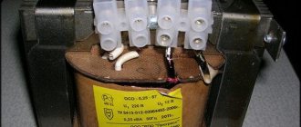
Homemade transformer
This component is the most problematic. Typically, 1500 W transformers are used for homemade devices.
For this, any element with a wire cross-section of more than 36 mm² is used. A ready-made primary winding is taken if it was used for a voltage of 220 W. If it is not there, then the motorist does the winding himself. The number of turns is determined through special services, where you enter the appropriate parameters. The secondary winding is removed and made into a copper busbar. The cross-section depends on the chosen circuit: with 4 diodes – 20 mm²; 2 diodes and 2 coils – 10 mm².
Secondary winding is more difficult to perform, since it is necessary to calculate the number of turns. This is done based on the number of turns on the primary winding (Nprim). The value is calculated using the formula Nsecond = (Nfirst/220)*12. When the data is unknown, they are determined empirically, for this:
- wind the secondary coil (10 turns);
- measure voltage;
- determine the parameters using the formula Nsecond = (Ntime/Utime)*12;
- The temporary winding is removed and made permanent.
RESULTS
RESULTS RESULTS ROOM ASSURANCE. RESPONSIBILITY, RESPONSIBILITY ¾ÑÐµÐ½Ñ Ð¿ÑоÑÑÑ. RESULTS, RESULTS, RESULTS. RESULTS LM317, LM317 логи. RESULTS, ASSURANCE, ASSURANCE, ASSESSMENT ÑÑади олÑбиÑелей. RESPONSIBILITY ¸ÐºÐ¸ Ñ Ð½ÐµÐ³Ð¾ пÑевоÑÑодÑÑ Ð¾ÑеÑеÑÑвеннÑе анало ги.
RESULTS TL431. RESULTS ine ° ROSS. LM317 LM317 еÂ" LOSS OFF. ROOM µÐ»Ñ Ð¸Ð´ÐµÑ Ð½Ðµ 12 Ð, а 15 Ð, Ñо “Р"иÑниеÂ" 3 РбÑдÑÑ ÑÑодиÑÑ Ð² ÑадиаÑоÑ. Ðð½³ mill ñ ñ ° ° ðices ñlish ñ ð ð · · ð ° ññ½ police ññ¾ñ²²² ° ð ° ð²ñ eth Ðently ð² ððµð ð ° ñññ ð ðµð · ñuth ±Ð»ÑÐ´ÐµÐ½Ð¸Ñ ÑÑÑÐ¾Ð³Ð¸Ñ ÑÑебований к внеÑней обо ROOM RESULTS.
We advise you to study the Oscilloscope yourself
Memory assembly
Step-by-step instruction:
- Create a transformer and circuit.
- Connect pins 9 and 9' together.
- Assemble a bridge on a fiberglass plate from diodes and radiators.
- Connect pins 10 and 10' to this bridge.
- Place a jumper between 1 and 1'.
- Attach a cord with a plug to 2 and 2' using a soldering iron.
- Connect fuses.
- Place a nichrome wire into the gap near the bridge, secure it on one side and connect the ammeter.
- Insulate the connections with electrical tape and place the device in the housing.
- Place the moving contact on the end of the wire and connect the battery.
During charging, the current will decrease as the process completes. During each procedure, it is necessary to control the tension. It is disconnected from the memory because the indicators are always higher than the real values. The first time the device is started is done through an incandescent lamp. It is placed in the gap between the neutral and phase wires on the primary winding.
The main disadvantage of the described device circuit is that it does not turn off the battery after reaching the appropriate parameters. The motorist will have to monitor the parameters with a voltmeter.
DIY crafts for car enthusiasts
Today I’ll tell you how to assemble a powerful charger for a car from scrap trash. The main requirements for it were the following: ultra-high reliability, so that it works without problems at sub-zero temperatures,
I was not afraid of short circuits, power reversal, and most importantly, it should be automatic and turn off when the battery is fully charged. I think it’s clear that there should also be a knob that regulates the charge current.
Among the additional criteria, if necessary, it should help the battery when starting the engine, that is, almost starting-charging, in a word, you need charging with all the amenities so that it never breaks down, in short, charging for a guy in the garage.
I immediately decided that I would do the charging on the basis of a good old iron transformer, which is much more reliable than all these impulse things of yours.
In order not to break traditions, the control circuits will be no less reliable, based on thyristors.
In this article we will assemble a circuit , study its operation and test it in action, but in the next article we will think about the case, installation as a whole, decide on the choice of transformer, in a word, we will get a complete device.
Once upon a time, such chargers were mass-produced, now they have been forgotten and the reason is not that they are bad, it’s just not entirely profitable from an economic point of view, the whole world has long switched to pulse technology.
For comparison, here is an iron network transformer of about 200 watts,
but pulsed with the same power,
the dimensions and weight differ tens of times, the copper in the pulse transformer is also orders of magnitude less.
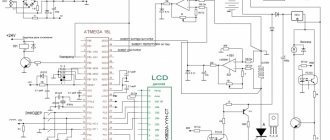
The circuit of the industrial charger Resurs-1 was taken as a basis; in Soviet times, this charger could be said to be popular,
I redrawn the diagram and transferred it to an imported element base, we will consider it exactly,
it has all the necessary options, turns off the battery when fully charged, is not afraid of polarity reversal and short circuits, and provides smooth adjustment of the charging current.
True, the original circuit is designed for a charge current of slightly more than 6 amperes, but we need a nuclear charger that, if necessary, should produce much higher currents.
In the original circuit, I indicated the components that are necessary to obtain currents of 10 amperes, but in the end I will supply 80 ampere power diodes and thyristors.
Well, now, according to tradition, let's look at the principle of operation of this circuit.
An adjustable rectifier is assembled using thyristors and diodes, or rather, only thyristors are responsible for regulation; our thyristors are controlled by this piece of circuit
which is a relaxation generator. It produces pulses with a certain frequency, this frequency can be adjusted with a variable resistor.
The signal from the generator, through separating capacitors, reaches the control terminals of the thyristors, which, opening at a certain point of the sine wave, cut it off, therefore the power at the output of the rectifier changes.
In fact, our circuit is a phase-pulse power regulator. Due to the pulse mode, the efficiency of the circuit is very high, but still the power components need a radiator if you are going to drive the device at high currents.
The next piece of the diagram is automation systems.
It is important to note that if the switch is closed, the automation is turned off and you just have a power regulator.
In manual mode, when the automation is disabled, charging can work without a connected battery. In this mode, we are deprived of protection, so I advise you to activate this mode only if there is a need to check the functionality of, for example, a light bulb or the charger itself.
Adjusting the current in this mode also works, but not as well as with a connected battery.
In this mode, the glow of the LED indicator will change depending on the current; in automatic mode, the LED will turn on sharply upon completion of the charging process.
When the switch is opened, the device operates in automatic mode, the circuit will only work when the battery is connected and will have all the protections and auto shutdown. In this mode, the control circuit will be powered by the battery itself.
A protective diode is installed at the input,
if you reverse the polarity, the diode simply will not open and the control circuit will not start - this is protection against reverse polarity.
And protection against short circuits works even simpler, without a battery there is simply no voltage at the output and no matter how you punish the wires you won’t even see a spark, it is also important to note that the circuit will start if the battery is very dead, since the operation of the control system begins at a voltage from 4-5 volts.
Let's consider the operation of the circuit in automatic mode.
In this mode the switch must be open,
when the battery is connected, the power will be supplied to the automation circuit, the indicated two transistors (VT4, VT2) will immediately work, the power through the VT4 transistor will be supplied to the relaxation generator circuit and it will begin to generate control pulses for the thyristors.
The power supply for this generator will be formed by rectifier diodes, the process of charging the battery will begin, as it charges, the voltage on it will increase, as soon as the voltage on the battery reaches the threshold, which depends on the type of battery and is set by the specified trimming resistor R2, the zener diode will break through and VT1 will open - transistor.
It will immediately close the subsequent transistor with a positive signal, and in parallel the LED indicator will light up, which plays a dual role, it is an indicator of the end of the charge, and it will also supply power to the base of the VT3 key and it will work.
When triggered through its open junction, the base of transistor VT4 will be shunted to the power plus and it will close securely, therefore the power supply to the relaxation generator will stop and the thyristors will close.
The circuit will stop working, that's the whole principle. It is also necessary to point out that in some sources there is an incorrect circuit in which the zener diode is connected incorrectly,
in the case of such a connection, the circuit does not work correctly, since the zener diode will work purely as a diode
in general, the circuit that came with the original charger is correct, the zener diode is connected precisely by the cathode to the base of the transistor.
About the components , in the circuit I used much more reliable medium-power transistors BD139-140, yes, this didn’t make much sense, but still, it’s better than the original ones.
It is also necessary to indicate that before soldering the trimmer resistor to the board,
it needs to be unscrewed to the middle.
After complete assembly, the operation of the automation system can be checked without connecting the power unit,
To do this, we connect a laboratory power supply in place of the battery, which needs to be set to about 14.4 volts, that is, the end-of-charge voltage, but it all depends on the type of your battery.
Next, we slowly rotate the subscript, multi-turn resistor until
When the LED lights up, the setup is complete.
Regarding the printed circuit board, I tried to make it compact.
Since the charging was done for myself, I wasn’t even lazy and applied silk-screen printing, and at the end I also varnished the board.
Now all that remains is to connect the power thyristors with diodes and, of course, the transformer. As I said earlier, my version will use miniature but very powerful thyristors with a current of 80 amperes, diodes also 80 amperes.
Considering the type of rectifier and the fact that in fact the power components tolerate currents greater than the maximum values, and also the fact that starting the engine takes a short time, with a good transformer such a thing can start a car engine, but only if a battery is installed in parallel and that not very dead.
And so, nothing prevents you from putting in, for example, these thyristors with diodes
and about a 3-kilowatt transformer and having received a starter that will start any passenger car engine even without a battery, but I highly do not recommend starting the engine without a battery, since the output voltage is pulsating and the value of these pulsations can be dangerous for the car’s electronics, and the battery is all that will smooth out.
The main power transformer should provide a voltage of about 18 volts on the secondary winding, with a current above 7 - 8 amperes.
Enter your email and receive emails with new crafts.
Don’t forget that we are working with a network device and following safety rules, and the first start-up of the device is done with a 40-60 watt safety network lamp, which must be turned on in place of the fuse.
Switch the device to automatic mode and see to what voltage the battery will be charged.
The multimeter will show the voltage on the battery,
current clamps show the charge current,
As you can see, when the voltage on our battery reached about 14 and a half volts, the automatic system worked
and the charge stopped, in a word, everything works fine.
The charging current is also adjustable, the minimum current is not zero, but in the case of car charging this is not necessary. The protection also works properly. This is how it turned out to be a charger for all occasions). Now all that remains is to cram it all into some kind of housing, but we’ll talk about that another time.
Signet in .lay format;
Author; AKA KASYAN
Popular;
- Charger for a car from a power supply from an LED strip
- Automatic charger with auto shut-off.
- Charger from power supply from computer
- Reverse polarity protection in 5 minutes for the charger.
- Very high quality battery charger
- Charger from a computer power supply
- Automatic battery disconnection or charger attachment
- Reverse polarity and short circuit protection circuit for battery charger
Exploitation
It is worth remembering that you cannot check a homemade charger “for a spark”. Apart from this, there are other precautions:
- unscrew the plugs to prevent the electrolyte from boiling during charging;
- the device will instantly fail if you mix up the plus and minus positions, watch this moment;
- the terminals are connected only in the off position;
- Only a multimeter whose scale exceeds 10A is suitable for operation;
- Before using the battery, it is necessary to clean the terminals from acid deposits; as a preventive measure, they are treated with lubricant.
A homemade charger will help start a dead car when there is no way to “light up” from another car. It is unlikely that you will have to use it often, but having such a device, which is also homemade, will allow you to avoid unpleasant situations and associated consequences.