An electromagnetic valve is a modern type of shut-off valve installed on heating, water supply, land reclamation, and technical water pipelines in industrial enterprises. The device is based on an electromagnetic coil - a solenoid, which receives a pulse from an external device (sensor or controller) and blocks or opens the flow of the working medium.
Purpose and principle of operation of the device
The main principle and advantage of using this device is automation. The valve was designed to shut off the flow of water or other liquid/gas when certain system parameters—temperature, pressure, speed, and flow —change without human intervention. This happens due to the electromagnetic field in the area of action of the valve core (plunger). When voltage occurs, it lowers or rises, depending on the conditions provided.
The working energy that drives the plunger is generated by the movement of electrons along the copper winding of the coil. The magnetism that appears when a pulse is applied from an external device is converted into a translational movement that lowers the plunger. The latter blocks the flow of water, avoiding large technological losses. As soon as the situation returns to normal, the tension disappears and the plunger rises, allowing water to continue moving through the pipes.
Important! Another advantage of the solenoid valve is its high response speed. Thanks to this, the device can shut off the flow of water in the event of an accident on a pipeline section within 2-3 seconds after the sensor is triggered. Due to this, valves are indispensable in heating systems, hot and cold water supply, and in technical pipelines in industrial enterprises.
Description and principle of operation of the solenoid
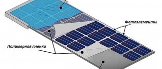
A linear solenoid operates on the same basic principle as the electromechanical relay described in the previous lesson, and just like relays, they can also be switched and controlled using transistors or MOSFETs. A linear solenoid is an electromagnetic device that converts electrical energy into a mechanical pushing or pulling force or movement.
A linear solenoid basically consists of an electrical coil wound around a cylindrical tube with a ferromagnetic drive or "plunger" that can freely move or slide the "IN" and "OUT" in the coil housing. Solenoids can be used to electrically open doors and latches, open or close valves, move and control robotic limbs and machinery, and even turn on electrical switches just by applying power to its coil.
Solenoids are available in a variety of formats, with the most common types being the linear solenoid, also known as linear electromechanical actuator (LEMA) and rotary solenoid. You can find and purchase these types and more on Aliexpress.
Both types of solenoids, linear and rotary, are available in hold (constant voltage) or latch (ON-OFF pulse) form, with latch types used in energized or power-off applications. Linear solenoids can also be designed for proportional motion control, where the position of the plunger is proportional to the power input.
When electric current flows through a conductor, it generates a magnetic field, and the direction of this magnetic field relative to its north and south poles is determined by the direction of current flow within the wire. This coil of wire becomes an "electromagnet" with its own north and south poles, just like a permanent magnet.
The strength of this magnetic field can be increased or decreased either by controlling the amount of current flowing through the coil or by changing the number of turns or loops the coil has. An example of an "electromagnet" is given below.
Design features
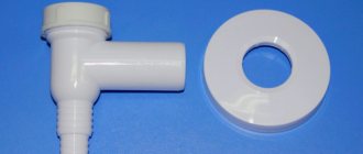
The valve device consists of a polymer or metal body, inside of which there is a solenoid, plunger, rod and membrane.
The material for the body is plastic, or stainless steel, brass or cast iron, which is determined by the scope of use of the valve. For example, a metal casing is used in systems with chemically aggressive or high-temperature media, while plastic casings are used for simple tap drinking or industrial fresh water. Valve membranes and seals are made from polymeric materials based on rubber and polyethylene.
Types of solenoid solenoid valves
The described devices are classified according to the following main characteristics:
- the material on which the body is made;
- valve design features;
- its position when the voltage is removed from the coil (de-energized);
- operating principle;
- features of connection to pipelines.
Important! The correct choice of valve for some of these characteristics determines how long it will work in an environment with the given parameters.
The body of these products is made of traditional brass, plastic or stainless steel. The correct choice of material greatly determines the ability of the valve to be used in critical applications. Any of the above varieties is suitable for household plumbing heating systems.
Based on their design features, valves are divided into piston, diaphragm and spool valves. The cheapest and most reliable option is a spool device, which does its job well. Therefore, such valves are traditionally installed in everyday life.
Types and scope of application
The scope of application of the solenoid valve is not limited to household activities. Along with centralized heating and water supply of apartments and houses, shut-off equipment can be seen in various technological systems, where they operate by triggering sensors and timers.
Widely used in the following systems:
- reclamation (watering) of lawns, garden plots, greenhouses - in such valves the plunger is in the normally closed position and opens when the timer programmed for a certain time interval of watering is triggered;
- public toilets, showers, car washes, washing systems in the car service industry - a similar principle of operation of the valve, based on the periodic operation of a timer that opens the flow of water;
- heating systems - used as protective devices that prevent technological losses due to burst pipes, as well as replenishing the volume of water in the system when it evaporates;
- in industry - devices serve as a kind of dispensers for supplying liquid for mixing various materials and raw materials.
The main task of the solenoid valve is the uniform and dosed distribution and supply of water. This ensures precise control of consumption and helps prevent losses of key plant resources.
Another purpose of using a valve is to regulate the basic hydraulic parameters of the pipeline. For example, in heating and hot water systems, a solenoid is installed to precisely control the movement and flow of water.
To do this, the device is connected to sensors programmed for a specific pressure or temperature. When the system is filled with water, the temperature of the pipes and radiators naturally rises to a critical level, which can lead to an accident. To prevent an undesirable situation, the valve is activated, cutting off the flow of hot water until the temperature in the systems is equalized.
By type, solenoid valves can be classified into several categories:
- according to the operating principle - normally open, normally closed and bistable;
- by type of operation - one-way, two-way, three-way;
- by type of solenoid - direct and alternating current;
- by type of connection - threaded and flanged;
- according to the method of operation of the mechanism - direct and pilot action.
Normally closed valves are installed such that the plunger is in the “closed” position. When an electromagnetic field occurs, it opens, allowing water to move through the pipes .
Such devices can be seen in watering systems for lawns, gardens, and greenhouses. Normally open valves in standby mode are in the “open” position and do not interfere with the flow of water. As soon as voltage appears on the induction coil, the plunger shuts off the water. Such devices are usually installed in heating, water supply, and sewerage systems.
One-way valves are simple devices that work either to shut off or to pass a working fluid through pipes. Two-way models can be used to prevent backflow of the working fluid. Three-way devices - the most complex in design - are used to mix water flows of different temperatures, for example, when connecting a “warm floor” system to centralized heating.
Types and features
Magnetic gas valves “Lovato” VN series are very diverse in operating principles and features of their application. There are several types and methods of classification of this device.
- normally open (NO). This group of valves remains in the open position after turning off the current supply. They are used on those pipelines where fuel must be supplied constantly and shut off only in emergency cases;
- normally closed (NC). Such devices are directly opposite to the previous subgroup. The task is to shut off the gas supply after the disappearance of the electrical impulse. They are convenient to install on household gas appliances, for example, water heaters;
- universal - after a power outage they can remain in either the closed or open position.
Internal structure of the valve
Principles of valve movement:
- direct action involves actuating the bolt solely by the movement of the core;
- indirect action suggests that the valve can be actuated not only by the movement of the core, but also by the movement of the gas itself. This subtype of Lovato chokes of the BH series is beneficial for systems with a large fuel flow.
Number of moves:
- two-way valves - valves in which there are only two holes: inlet and outlet. This type is used in cases where it is only necessary to supply or shut off the gas supply in the pipeline;
- three-way - devices with three holes: one inlet and two outlets. It is convenient in cases where it is necessary not only to shut off, but also to redirect the gas flow in the system;
- Four-way valves have one inlet and three outlets. They allow you not only to shut off or redistribute the gas flow, but also to connect to additional systems.
How to choose a solenoid gas valve?
To choose a “Lovato” VH series solenoid gas valve, you need to decide where it will be used and, therefore, what properties it should have.
Pneumatic shut-off valves
When choosing this device, pay attention to the following characteristics:
Electrical maintenance. It is better to choose valves with low power and intrinsic safety, or with additional manual adjustment. Pressure
When choosing a valve, you need to pay attention to the pipeline. It must not be higher than the rated pressure of the accessory
High pressure can damage the mechanism. Environment. Do not neglect the external conditions in which the valve will be operated. The characteristics of the device itself must necessarily coincide with environmental conditions, such as humidity, temperature changes, vibration, direct sunlight and other conditions other than normal. The external environment can adversely affect both the entire mechanism as a whole and its individual elements. Network voltage. It is worth paying special attention to this parameter, since high or low voltage can lead to improper operation or even failure of the valve mechanism.
Prices for Lovato BH series solenoid valves vary depending on size, type and application. For example, the price of equipment for a gas water heater is in the range of 4-10 dollars, and for gas equipment for a car - from 10 to 15 dollars.
Gas solenoid valves differ in connection method, operating pressure, installation environment and actuator power supply.
Similar devices intended for industrial use are several times more expensive.
Installation nuances
The “Lovato” VN series solenoid valve is installed in rooms after the gas valve. It is recommended to install a filter in front of it to avoid clogging of the valve itself.
When installing the equipment, pay attention to the arrow on the housing. It should show the direction of gas movement
The gas pipeline on which the throttle is installed must be located strictly vertically or horizontally. On pipelines with a small diameter, valves are installed using threads, and on pipelines with a large diameter, using flanges.
Installation and operation rules
Thanks to the manufacturer's instructions on the device body, installation of the solenoid valve is as simple as possible. It will be easy for someone with engineering skills to install the valve on a section of pipeline. Key recommendations for installing the device:
- the valve must be positioned strictly in accordance with the arrows on the device body indicating the direction of water flow;
- It is recommended to install a dirt filter on the supply section of the pipe in front of the valve itself to catch particles (they should not get into the valve device, since they quickly cause the device to fail);
- the device is connected to the power source only after installing it in the pipeline and checking the tightness of the connection;
- it is important to ensure that there is no weight load from the pipes on the device;
- When installing outdoors, you must isolate the device or select a model with the appropriate IP level.
Otherwise, the installation of the valve is no different in principle from other types of shut-off valves. For example, when using a device with a threaded connection, you need to make a thread on the pipe using a special tool. Immediately before installation, the pipe must be prepared - cleaned of dirt and burrs, and degreased with solvents.
Important! When installing a solenoid valve, the main regulatory function must not be assigned to it. It is used as an auxiliary device, and a ball valve or valve must be installed on the pipeline section as the main shut-off device.
Solenoid valve, its purpose and design
Proper automation of the process of controlling the flow of steam, water or air is a complex task that requires the use of special instruments. One such device is a solenoid or solenoid valve. It is actively installed on fresh water, freon or air pipelines.
What is a solenoid valve for?
The main function of the solenoid is to remotely control the transport of air, liquid or gas. The process can be done either manually or fully automated. Due to the above aspects, such an electromagnet has become very popular for regulating modern pipeline systems. Solenoid valve , characteristics are particularly durable and reliable, can be used both to perform complex technological tasks and for domestic use. Each person will be able to independently adjust the volume of air or liquid at a certain point in time.
Solenoid valve - mechanism description
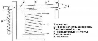
The solenoid valve is a device that consists of the following components:
- Housing, which can be conventional or explosion-proof;
- The solenoid or electrical coil, which must be reliably protected by a sealed, dust-proof housing;
- Lid;
- Stock;
- Piston;
- Plunger;
- Spring.
To ensure proper functioning of the part, it is necessary to monitor the condition of each of the parts listed above. The design of the solenoid valve should be carefully studied, this will help in the event of a breakdown to determine the root cause of the malfunction.
Advantages and disadvantages
The device has a number of main advantages, which include the following aspects:
- Relatively simple type of construction;
- The ability to independently manage and adjust all processes;
- The device has good characteristics of reliability, practicality and functionality;
- Fairly simple installation.
But to obtain complete information, it is necessary to consider the disadvantages that affect the main purpose of the solenoid valve .
- The device needs to be connected to an electrical network;
- High probability of breakage in case of improper handling;
- Higher cost than manually operated shut-off valves.
When buying such a device, you need to carefully read the above pros and cons. This way, you can truly make the right choice.
A valve with an electromagnetic drive is a modern type of shut-off valve. They allow remote control of liquid or gas flows in pipeline systems. Such valves are well integrated into automated process control systems, save scarce human resources and make the operation of enterprises safer. There are a large number of different types of valves for different environments; they differ in their design and purpose.
Electromagnetic valve actuators - types and principle of operation
The content of the article:
Electromagnetic drives of fire dampers Types of fireproof valves with an electromagnetic drive Types of electromagnetic drives Operating principle of an electromagnetic drive Comparison of characteristics with an electric drive Advantages and disadvantages compared to electromechanical drives
Solenoid drives for fire dampers
An electromagnetic drive is a spring-action device with an electromagnetic latch, which is necessary to control the operation of fire-retarding and smoke dampers. The main components of the EM drive are a torsion (return) spring and an electric magnet, which fixes the damper in its original state (closed for smoke dampers, open for fire dampers).
The mechanism uses DC magnets designed for voltages of 12V or 24V, and devices equipped with a 2-half-wave rectifier, operating from a conventional AC power supply with a frequency of 50 Hz and a voltage of 220V. The electromagnetic drives of the fire and smoke dampers are equipped with microswitches to control their status. Limit switches (KV1/KV2) signal the current position of the damper, which can be open or closed. The current range in the control network is from 0.1 to 2A (in case of resistive load), from 0.25 to 4A (in case of inductive load with direct current), from 0.3 to 2A (in case of inductive load with alternating current).
The control signal for actuation of the valve flap with an electromagnetic drive is the supply of power to the electric magnet. Then it is necessary to remove the voltage from the electromagnet (220V) to protect operating personnel from electric shock.
Types of fire protection valves with solenoid drive
- Depending on the purpose and installation location, fire protection valves with an EM drive can be divided into three groups:
- Normally open (NO) with fire resistance limit EI - used in supply-type general ventilation systems;
- Normally closed (NC) with fire resistance limit EI - designed for installation in supply smoke ventilation ducts;
- Normally closed (NC) with fire resistance limit E - for smoke removal, installed in shafts or air ducts of smoke exhaust ventilation.
Spring actuator with magnetic latch and thermal lock are supplied together with normally open (NO) fire dampers, which resist the free passage of fire through the ventilation ducts, i.e. perform a fire retardant function.
Thermal lock (TZ) is a heat-sensitive element used to duplicate automatic operation in fire conditions.
A similar device, but without a temperature sensor, is installed on fire-retarding OZK with a normally closed damper.
Electromagnetic smoke removal drives are installed on smoke dampers, in which the damper is in the closed state by default.
Example of application – KLOP WINGS-M
Bug 1 NO-rectangular Normally open fireproof
Klop 2 NZRectangular Normally closed fireproof
Bug 1 EI60/90Round Fireproof for round air duct
Bug 3Double damper Fireproof with shorter length
Types of electromagnetic drives
The main difference between regulating devices with a magnetic latch is the supply voltage: 12V, 24V and 220V. The degree of protection of the housing may vary, depending on the model, from a minimum of IP10 to a maximum of IP54 (protection from moisture and dust). Also, some modifications may have a built-in function for automatic shutdown and performance testing (for example, M183).
Comparison of characteristics with electric drive
Electromechanical fire-fighting electric drives are connected to a 230V AC or 24V DC network; drives with an electromagnetic latch have the same parameters, but also the ability to connect 12V (DC).
| Feature comparison table | |||
| Model | EMK 25-211-3 54U3 | Model | Dastech FR-05N220S |
| Rated voltage | 220V, 50Hz | 220V, 50Hz | |
| Nominal traction force | 120 N | Torque | 5 Nm |
| Nominal armature stroke | 4.5±0.5 mm | Angle of rotation | 90° (max 95°) |
| Rated power | 66 W | Power consumption | 5 W / 3 W |
| Return time | 2 sec | Spring rotation time | 20 sec |
| Limit switches | There is | There is | |
| Weight | 1.45 kg | 1.5 kg | |
Operating principle of electromagnetic drive
The damper rotates when voltage is applied to the magnet or when the thermal lock is broken (usually set at 72°C). The magnet lever releases the damper, and the spring moves the damper from its original position to the operating position. In this state, the damper is secured with a bolt. Thus, the transition from the initial state occurs automatically (for NO and NC valves), when the thermal lock is operating (for NO), remotely from the control panel or from a lever or button on the valve itself. Return - from the working state to the original - exclusively manually, using a key or handle.
Advantages and disadvantages compared to electromechanical drives
- Advantages:
- Prompt (in time - no more than 2 seconds) installation of the valve flap into working condition, despite the fact that for electromechanical electric drives this value reaches 30-150 seconds for the engine and 20-30 seconds for the return spring;
- Compact overall dimensions;
- Low price compared to electromechanical analogues.
- Main disadvantages:
- The need to return the damper after its operation to its original state in manual mode;
- When valves are connected to a group, the control signals the operation of all valves included in it. Therefore, when designing, it is necessary to more carefully group valves by control;
- High power consumption is 30W-60W, while electromechanical ones have 5-10 W for the motor, spring retention is from 2 to 5 W.
And despite its small size, the weight is quite comparable to electric drives - 1.4-2 kg. There is no difference in this parameter.
Purpose and application of solenoid valves
The solenoid valve is designed to control the flow of liquid and gaseous products at a distance. It can be shut-off or regulating. Control can be carried out either manually or using automation systems. In its design and purpose, an electromagnetic shutter is very similar to a regular one, with the difference that the locking element is driven not by muscular force, but by a solenoid, an electromagnet with a movable core. When voltage is applied to the solenoid inductor, it, depending on the polarity, pulls in or pushes out the core connected to the valve stem.
Such shut-off and control devices are used both in complex industrial installations and in home heating and water supply systems, and in household appliances. They are also used in vehicles running on liquid fuel.
Areas of application of the device
With the help of this drive, problems of power mechanical support of various levels are solved. In the most critical and complex systems, sealless fittings are used to control electromagnetic devices, which increases the reliability and performance of the equipment. In this combination, units are used in transport and communication pipeline networks, when servicing storage facilities for petroleum products, in the chemical industry, at processing stations and plants in various industries. If we talk about simple devices, then an electromagnetic fan drive for supply and exhaust systems is common in the domestic sphere. Small-format mechanisms also find their place in sanitary fittings, pumps, compressors, etc.
Operating principle of electromagnetic systems
The operating principle of the electromagnetic shut-off valve is based on the physical phenomenon of electromagnetic induction. When current flows through an inductor, a magnetic field arises inside it, acting on a core of magnetic materials with a force applied in the longitudinal direction. This force, depending on the polarity of the applied voltage, tries to pull the core inside the coil or push it out. In this case, the shutter element opens or closes.
Solenoid valve coils can operate on either 5 to 36 volt DC or 220 V AC.
Devices with low control voltage have low power and limited force transmitted to the locking element. This allows the use of low-voltage semiconductor circuits to control them. Such devices are used in low pressure systems of the working medium, on pipelines of small diameters.
Drives operating on alternating current develop much greater forces and can be used on main pipelines of high pressure and large diameters.
Why is a solenoid valve needed?
Solenoid valves are a category of modern shut-off valves for pipelines for a wide variety of purposes. In everyday life, such electric valves are used in cars, special equipment, water supply systems and automatic watering and heating systems.
They are also widely used in industry to regulate current and control the transport of a variety of liquids and gases.
The solenoid valve is a volatile equipment; it requires power to open or close.
The solenoid valve for water or gas does not have any sensors inside. With its help, you can only regulate or completely block the flow of the working environment. If automation of these processes is required, then you will have to additionally install external measuring instruments, tying the operation of the electrovalve to them.
For example, use an additional controller and a water leakage sensor in combination, so that when a leak is detected, the solenoid valve receives the appropriate command from the controller and shuts off the pipeline.
The advantages of using solenoid valves include:
- quick adjustment of the working medium current through the pipeline;
- versatility and reliability of the device;
- long service life;
- small size and light weight;
- variety of instrument types.
The valve operates literally within a split second after the signal is given. It is designed to work with liquids under different pressures, from 0 to 25 bar, and with varying temperatures, from -20 to +120 ° C. At the same time, in a de-energized state, such an electric valve can remain either in a closed or open position - it all depends on the modification of the device.
Most often in everyday life, a solenoid solenoid valve is used in water supply and heating systems, where it is used to remotely regulate the water flow
In water supply systems, it allows you to automatically shut off the water supply if the pipes burst. And in heating systems, such a valve is used as a device for regulating the flow of coolant.
Here, using an external temperature sensor, it independently reduces or increases the flow of heated liquid from the boiler to the radiators.
About the types of products
Products are classified according to several parameters.
Based on the position of the locking element in the absence of voltage on the coil, the following are distinguished:
- Normally open, or BUT. The passage for liquid or gas is open, but when voltage is applied, it closes.
- Normally closed, or NC. The passage for the medium is blocked, and when voltage is applied it opens.
Some models are produced as universal ones, and normally the position of the locking element is adjusted during installation and connection to the control network. Such switched devices are called bistable.
Depending on the working environment, shut-off valves are produced for:
- Air.
- Water.
- Pair.
- Active media
- Fuels and lubricants.
Devices for working in radioactive environments are distinguished by a special selection of materials with increased radiation resistance. The vacuum solenoid valve must provide particularly high tightness
Based on the characteristics of the external environment, the design of the device can be:
- Normal
- For wet areas.
- Heat resistant (for high temperatures).
- Frost-resistant (for extremely low temperatures).
- Explosion-proof. Such devices should not spark when turned on or off. For this purpose, they use special design solutions and materials.
According to the type of supply voltage, coils are divided into
- AC, high voltage. They develop high forces and are used on main pipelines of high pressure and large diameters.
- Direct current, low voltage. Used on pipes of small cross-section and low pressure.
There is a separate class of high pressure solenoid shut-off valves. They are called cutoffs. They are designed to instantly shut off pipelines or seal containers in the event of abnormal or emergency situations.
And finally, according to the type of functioning, valves are divided into
- One-way. This type of valve has only an inlet pipe. Usually they are normally closed and open the way for water or air flow to the external environment. Used as safety precautions.
- Two-way. The most common type has inlet and outlet pipes and is mounted in a pipeline break. They are used to control the flow in one of the circuits of the pipeline system.
- Three-way. They may have one inlet and two outlets, or two inlets and one outlet.
Three-way valves of the first type are used to redirect flows from one circuit to another (for example, in a heating system). This allows you to maintain the temperature of the working environment constant without changing the operating parameters of the heat source. Devices of the second type are used to mix two streams having different temperatures. A typical example is the single-lever ball mixer in the kitchen or bathroom.
Rotary solenoid
Most electromagnetic solenoids are linear devices, producing linear force or forward and reverse motion. However, there are also rotary solenoids that produce angular or rotational movement from a neutral position in either clockwise, counterclockwise, or both directions (bidirectional). Rotary solenoids can be used to replace small DC motors or stepper motors if the angular motion is very small and the rotation angle is the angle offset from the start to end position.
It will be interesting➡ Diode bridge - what is it?
Typically available rotary solenoids have movements of 25, 35, 45, 60 and 90 o, as well as multiple movements to and from a specific angle, such as self-restoring in two positions or returning to zero rotation, for example, from 0 to 90- to -0 ° , self-healing in 3 positions, for example from 0 ° to +45 ° or from 0 ° to -45 °, and locking in 2 positions.
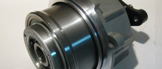
Solenoid in a metal housing.
Rotating solenoids produce rotational motion when energized, de-energized, or changing the polarity of the electromagnetic field changes the position of the permanent magnet rotor. Their design consists of an electrical coil wound around a steel frame with a magnetic disk connected to an output shaft located above the coil.
When the coil is energized, the electromagnetic field generates multiple north and south poles, which repel the adjacent permanent magnetic poles of the disk, causing it to rotate at an angle determined by the mechanical design of the rotating solenoid.
Rotary solenoids are used in vending machines or gaming machines to operate valves, chamber shutters with special high speed, low energy or high force or torque adjustable positioning solenoids such as those used in dot matrix printers, typewriters, vending machines or cars.
Solenoid device diagram.
Area of use
The use of electromagnetic valves is carried out in a variety of areas of human activity, wherever there is a need to control the flow of liquids and gases remotely. This includes:
- Domestic heating systems.
- Water supply and water treatment systems.
- Technological installations.
- Pipeline transport.
- Heat generation and distribution.
- Appliances.
- Sewerage.
- Irrigation.
- Vehicles.
The use of solenoid valves in transportation is gradually declining as more types of vehicles switch to electric power sources and abandon liquid fuels and hydraulics, replacing them with more reliable electric drives. Similar prospects are visible in heating systems. But in water supply, sewerage and other industries, the role of electromagnetic gates will only increase.
Electromagnetic fittings
The drive actuators can operate in different configurations, performing certain actions required for the operation of a specific operating infrastructure. But in any case, the function of the core or power element alone will not be enough to provide a sufficient effect in terms of performing the final task, with rare exceptions. In most cases, a transition link is also required - a kind of translator of the generated mechanical energy from the direct drive mechanics to the target device. For example, in an all-wheel drive system, the electromagnetic clutch acts not just as a force transmitter, but as a motor that rigidly connects the two parts of the shaft. Asynchronous mechanisms even have their own excitation coil with pronounced poles. The leading part of such couplings is made according to the principles of the rotor winding of an electric motor, which completely gives this element the functions of a converter and force translator.
In simpler direct-acting systems, the task of transmitting force is performed by standard ball bearing devices, hinge and distribution units. The specific design and configuration of the action, as well as the relationship with the drive system, are implemented in different ways. Individual schemes for interfacing components with each other are often developed. In the same electromagnetic drive coupling, an entire infrastructure is organized with its own metal shaft, slip rings, collectors and copper bars. And this is not counting the parallel arrangement of electromagnetic channels with pole pieces and contours for the direction of magnetic field lines.
Advantages of solenoid valves for water
The main advantage of the device is the ability to remotely and quickly regulate the flow of the working environment. Without electromagnetic shutters, the operation of complex technological installations and simple household appliances, such as a coffee maker and washing machine, becomes impossible.
In addition, the electric drive allows:
- Connect the solenoid valve to a centralized and automated control system. This greatly increases the accuracy and efficiency of parameter adjustments compared to manual control.
- Reduce labor costs for managing technological processes.
- Increase production safety and eliminate the operator’s exposure to harmful factors in the production environment.
- Increase the efficiency of household appliances and production plants through precise and fast control of the flow of working media and their parameters.
An important advantage of a solenoid drive compared to an electric motor and gearbox is the absence of gears and worm gears, exceptional simplicity of the device and a minimum of moving parts.
This ensures high equipment reliability, minimal wear and a long service life.
Design and principle of operation of the solenoid valve
The solenoid valve, also called the forced idle economizer (IAF), is an integral component of any carburetor in modern cars. The active use of this unit began in the 80s of the last century, when the “battle” between injection and carburetor units intensified. This is largely due to the fact that the former had noticeably lower fuel consumption, and this already captivated a larger number of motorists.
In order to minimize the consumption of carburetor engines, automotive engineers began to actively electronize them. In a few words, the essence of the latter was to reduce fuel consumption through the use of electronic devices. As a result, electronization resulted in the appearance of a carburetor solenoid valve, as well as a number of other electrical devices in the design of this unit
But why was this necessary and how did it help the competition between carburetor engines and injection engines? In order to answer this question, it is worth paying attention to the operating principle of the EPHH.
So, the carburetor solenoid valve is a device that runs on electric current and performs very specific functions. More precisely, it works to organize stable and optimal idle speed in the so-called forced mode of engine operation. The essence of the optimization is that when the engine operates in modes that do not require fuel consumption (switching to a lower gear, coasting, etc.), the EPHH turns off its supply without involving the throttle valve in the movement at all. This happens by transferring fuel through special channels at idle. During this transportation, only the idle jets, valves and some paths in the carburetor function, that is, its chambers and throttle valve are completely inactive.
As a result, we succeed:
- firstly, save fuel when the engine operates in the previously noted forced running mode;
- secondly, organize a stable and optimized idle speed;
- thirdly, to ensure high-quality and problem-free engine warming up for the driver during startup (by increasing the fuel supply with the same EPH);
- fourthly, eliminate unnecessary functioning of the throttle valve and a number of other components in the carburetor;
- and fifthly, optimize the operation of the entire motor, which significantly extends its service life.
Note that the economizer operates under the control of a special unit called the “carburetor solenoid valve control unit.” This device constantly analyzes the operation of the motor, based on sensor readings (speed, engine temperature, etc.), after which it gives appropriate instructions directly to the EPHH, and it, in turn, through the movement of the rod (small needle) either closes to the desired position fuel supply channels at idle, or vice versa, opens them. In general, there are no particular difficulties in a working economizer, which is clearly shown by the description of the device presented above. For even greater clarity of everything described, we recommend that you familiarize yourself with the following pictures:
Connection diagram for a typical EPHH:
Operating principle of the valve together with the control unit:
DIY water solenoid valve installation
Before proceeding with installation, you must determine the type of connection. The most commonly used are:
- Threaded. The inlet and outlet pipes are equipped with external or internal threads; through the corresponding fittings, the fittings are built into the pipeline gap. The most convenient for self-installation, it is better to choose this type of connection.
- Flanged. The pipes are equipped with flanges; the ends of the pipes must also have flanges of the appropriate standard size; they are tightened together with bolts. They provide high pressure and flow intensity, often used on high and medium pressure lines.
Before installing the device, a number of preparatory operations should be performed. Pipes must be marked, cut to size and cleaned. The location for installing the electromagnetic device must provide free access to the device for its installation, maintenance and repair. Experienced professionals also formulated several recommendations:
- All work on installing or removing the device can only be carried out when disconnected from the network.
- The pipeline system must be supplemented with a mechanical cleaning filter. This will prevent contamination and damage to parts by foreign matter such as sand, rust flakes and lime deposits.
- The device body should not bear the weight of the pipeline section.
- The device should be connected in accordance with the arrows marked on the housing. They indicate the direction of flow.
- When installed outdoors, the valve should be protected from exposure to natural phenomena. A waterproof casing is usually sufficient. When working in low temperature conditions, the casing must be heated.
- Threaded connections must be sealed with FUM tape or plumbing thread.
- The cable for connecting to the control system should be copper. It must have a sufficient cross-section of at least 2 mm 2.
The selection of a specific model is carried out based on calculations of the parameters of the pipeline system.
The pressure, pipe cross-section, required response speed and characteristics of the controlled medium should be taken into account.
Principle of operation
The operating principle of a pilot (indirect) solenoid valve for water can be understood from the attached diagrams of the device. Regardless of the type of electric valve used (normally closed, normally open or bistable), the operation of an electrically controlled valve will look something like this:
- The solenoid valve is initially closed and no electrical signal has yet been sent to the coil. Water is locked in the inlet part of the valve by a stem with a gasket;
- When an electrical signal enters the coil, an electromagnetic force arises in the solenoid, which draws the rod (plunger) into the inside of the coil, thereby creating space between the rod and the space above the membrane. The pressure under the membrane overcomes the pressure above and a passage opens for fluid to flow through the valve body.
When the tap is open, the same process occurs in the reverse order - the plunger is pushed out of the solenoid body and opens the water pressure above the membrane and, together with the force of the spring, closes the passage of water through the valve body.
The simplest operating diagram of a direct-acting solenoid valve:
- When a signal is applied (the electrical circuit is closed) to the solenoid, the rod is pulled into the inside of the coil and opens the passage of liquid due to the difference in pressure from the inlet to the outlet of the valve;
- when the signal to the solenoid coil stops (the electrical circuit is open), the spring returns the rod to its place and the valve seat blocks the flow of fluid through the valve body.
The solenoid valve can be made in different types of designs:
- saddle type solenoid valve;
- valve using a membrane floating amplifier;
- valve using a diaphragm amplifier with forced lift;
- piston type solenoid valve;
- gate type valve;a
- hinged valves;
- lever valves;
- poppet type solenoid valves;
- spool valves.
Based on the type of current supplied to the induction coils, solenoid valves can be divided into:
- installations with direct current in the network, which is typical for products where there is no high pressure and there is no need to create a large force of electromagnetic radiation;
- Products for networks with high pressures use alternating mains current to create an electromagnetic field of large magnitude on the rod or membrane in order to overcome large resistance loads in the water or gas environment.
Also, electromagnetic valves are divided according to the operating position of the rod into:
- Normally closed;
- Normally open;
- Bistable - with switching the position of the rod depending on the incoming electrical pulse signal.
Normally closed
An electromagnetic normally closed valve for water has a valve closed by a rod when the coil is de-energized, blocking the flow of liquid. When an electrical signal is applied to the solenoid coil, the rod and valve open this passage.
Normally open
Solenoid valves for water are normally open, such as, for example, UNIPUMP BOX series, when the selenoid coil is de-energized, they are in the open position and the liquid has a free flow through the valve body. When an electrical signal is applied, the valve and rod close this passage and the fluid flow stops.
Signs of a malfunctioning carburetor solenoid valve
The latest carburetors use a solenoid drive to control the fuel supply. How to check the solenoid valve for serviceability?
Its breakdown is determined by the following signs:
- The engine runs unsteadily at low speeds.
- The motor stalls when coasting.
- After turning off the engine, detonation of the working mixture is observed.
Indirect signs of a malfunction are also a decrease in speed when connecting powerful electricity consumers, such as a radio, low or high beam, heated windows.