Optimal and nominal modes
Nominal and optimal modes are otherwise called working modes. Since in their case the voltage and power are close to the nominal values. The transformer is designed for such conditions.
In rated mode, the primary winding of the transformer receives current and voltage of the rated value. But in fact, this rarely happens. After all, the electrical network does not have ideal stability: voltage surges occur. Such conditions are ideal for the operation of the device itself, but it will not work as efficiently as possible under them.
In optimal mode, the transformer shows maximum efficiency. Most often this happens if the load is about 50-70% of the nominal value. Current transformers have an output efficiency of 90% or more.
As a rule, the operating modes of the transformer change along with the load.
Idle mode
When idling, there is voltage in the primary winding, but the secondary winding is not connected to the distribution network. The energy goes to nowhere, so the efficiency in this case is zero.
When it is necessary to determine the value of the equipment transformation ratio, the amount of losses in the windings and core, and the characteristics of the magnetizing branch of the equivalent circuit, the transformer is switched to idle mode. For such tests, the primary winding of the transformer is connected to the rated load.
And voltage transformers are working in no-load mode, and not just being tested.
Transformer in parallel operation mode
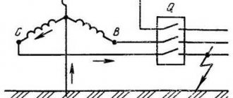
It is advisable to install two transformers at once in the networks of energy consumers of categories I and II. In such complete substations, it is important to place the equipment so that the load is distributed evenly.
How to avoid overloading one of the transformers:
- it is necessary to provide the same groups of winding connections in the devices;
- the difference in the transformation ratio should not exceed 0.5%;
- the ratio of the rated power of devices should be no more than 1/3;
- short-circuit voltage indicators should have a difference of no more than 10%;
- Be sure to phase the equipment.