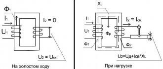
Principle of operation
A power transformer with oil filling uses an oil conservator in its operation, which compensates for the heating of the oil during operation. The most important part is the air cleaner, which helps protect against foreign bodies entering the oil tank. Also, this type of transformer must have a thermometer that determines the level of heating of the liquid. These devices have excellent reliability indicators, which is the main property in the power grid.
Operating principle of an oil transformer.
The advantage of oil transformers over dry transformers is a high degree of protection of the external winding, and they also have lower reactance.
These and many other properties provide high reliability indicators, and they can also significantly reduce supervision. Under good conditions, transformers of this type can last about twenty years and never require maintenance, which is certainly a significant plus in the purchasing decision.
According to statistics, the most common failure of a power oil type transformer is overheating of the liquid barrel, which causes depressurization of the transformer housing. But it is worth noting that compared to dry transformers, this breakdown will not be so difficult to fix in a service center.
Oil-type power transformers are very popular all over the world. This is due to their not very complex device, and the simpler the device, the more difficult it is to break. Also, high wear resistance is achieved by immersing the winding in technical oil, this provides a high degree of protection from external factors.
terms of Use
CT requires a high degree of reliability with high voltage and power values. This affects the quality of operation and prevention. Routine work is carried out for proper, complete maintenance, repair, testing, and adjustment. Transformers and equipment are located in the place where personnel are constantly on duty. Daily inspection schedules, control and measurement devices check the operating condition of the electrical network and transformers.
Monitor the readings of instrument sensors, measure:
- Temperature.
- Pressure.
- Oil level.
- Degree of desiccant depletion.
- Condition of oil regenerators.
Also read: Design and features of a traction transformer
Checks for oil leaks in the transformer cage, outdoor switchgear, closed switchgear, mechanical damage in the housing, flange joints (oil, coolant), radiators, fans, pipe sections. The number of operating fans and the oil level in the gas analyzer are monitored at a certain transformer load. For each mode, its own number of operating equipment, parameters of the cooling medium, gas, water, oil are given. In devices with permanent staff duty, inspections are done less frequently: once every 30 days. At least once every ½ year, an inspection of outdoor switchgear, indoor switchgear, indoor switchgear, and transformer points is carried out.
According to the maintenance schedule, during maintenance, oil is added and unsuitable transformer oil is replaced with a new composition. The quality of the oil is determined by chemical laboratory analysis. The PUE, instructions for transformers and equipment provide criteria for oil requirements, visual inspection, and color. In emergency situations or sudden changes in outside air temperature, unscheduled inspections are carried out.
Protection is subject to verification. Once every 365 days for major repairs, the oil is taken for laboratory analysis. The frequency of maintenance of voltage regulation devices of power transformers is associated with checking the contacts of copper and brass for oxidability. They perform preventive maintenance, cleaning, lubrication, reassembly, and tightening with a torque wrench to reduce the transition resistance in the contact assembly.
In order to change the oxide film, 2 times every 365 days the transformers are disconnected from the electricity, their load is removed to 0, the switches are placed in various adjustable positions several times. Methods of changing positions are done during the transitional autumn-winter period until the maximum load is gained.
Equipment selection criteria
There are many different aspects that must be taken into account when using power equipment. So the choice of transformer model is influenced by the conditions of its potential operation and in particular:
- scope of application;
- installation location;
- total power of consumers.
Let's consider the specifics of the choice, taking into account each of them. One of the main parameters is the scope of application. Focusing on it, you need to decide on such characteristics as:
- power, it must correspond to the expected loads and allow the unit to cope with overloads;
- the ability to operate the device as the load increases;
- cost and service life.
However, when choosing a transformer, you need to be able to correctly determine its main parameters:
- primary and secondary voltage;
- current frequency;
- phasicity;
- load;
- location method;
- placement features.
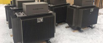
Industrial oil transformer.
But in addition to all the listed characteristics, the functionality of the unit, as well as its direct purpose, must also be taken into account. If a transformer is supposed to be connected to a circuit of measuring instruments, then use the appropriate type of device.
To protect against surges in the network, choose a unit that is not highly accurate, but has the necessary functions. Dry transformers have become the most popular recently; they are often used instead of oil transformers and have a large number of advantages.
Interesting read: how to assemble a Tesla coil yourself.
How to choose a power transformer
The choice of power transformer for operation in enterprises is based on the selection of power, as well as in accordance with the requirements for power reliability. To ensure uninterrupted power supply, in some cases it is necessary to install several transformers. The power of each device is selected in such a way that if it fails, other devices are able to take over the functions of this missing link, taking into account possible overloads.
Another important criterion is the availability of protection:
- From internal damage. Provided with devices that monitor the presence of gases, temperature, pressure and oil cooler level;
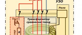
- From overloads. The so-called differential protection is used when current transformers are installed on each phase.
Device design
Power transformers are designed to convert (transform) alternating current of one voltage into alternating current of another voltage - lower or higher. Transformers that lower the voltage are called step-down, and those that increase the voltage are called step-up.
It will be interesting➡ How does a power transformer work and where is it used?
Transformers are made with two windings and three windings. The latter, in addition to the LV and HV windings, have a MV (medium voltage) winding. A three-winding power transformer allows you to supply consumers with electricity of different voltages.
Diagram of the oil transformer device.
The winding connected to the power source network is called primary, and the winding to which electrical receivers are connected is called secondary. In the switchgears and substations of industrial enterprises under consideration, three-phase two-winding step-down transformers are used, converting voltages of 6 and 10 kV to 0.23 and 0.4 kV.
Depending on the insulating and cooling medium, oil transformers TM and dry transformers are distinguished. In oil-based ones, the main insulating and cooling medium is transformer oils; in dry ones, it is air or a solid dielectric.
In special cases, transformers are used with tanks filled with non-flammable liquid - sovtol. The basis of the transformer design is the active part, consisting of a magnetic core with low-voltage windings 3 and high-voltage 2 taps located on it and a switching device.
The magnetic core, made up of separate thin sheets of special transformer steel, insulated from each other by a coating, consists of rods, an upper and lower yoke. This design helps reduce heating losses from magnetization reversal (hysteresis) and eddy currents.
The connecting wires coming from the ends of the windings and their branches, intended for voltage regulation, are called taps, which are made from bare copper wires or wires insulated with cable paper or getinaks tube.
Interesting material for review: useful information about current transformers.
We recommend our products
Transformer TM 40/06/0.4
50,000.00₽ View →
Transformer TSZGL 1250/06/0.4
420,000.00₽ View →
Transformer TSZ 1250/10/0.4
Price is negotiable View →
Transformer TSL (TSZGL) 63/10/0.4
65,000.00₽ View →
Transformer TMG 1600/06/0.4
750,000.00₽ 650,000.00₽ View →
Transformer TMZ 630/06/0.4
180,000.00₽ View →
Transformer TMVM 1000/10/0.4
180,000.00₽ View →
PKU 10/10 2tt, 2tn
155,000.00₽ View →
Transformer TMG 1250/06/0.4
500,000.00₽ View →
Transformer TM 40/10/0.4
50,000.00₽ View →
KTP KK-T 25-250 kVA
135,000.00₽ View →
Transformer TM 100/10/0.4
70,000.00₽ 65,000.00₽ View →
Transformer TMF 630/10/0.4
160,000.00₽ View →
Transformer TM 63/06/0.4
60,000.00₽ View →
Switching devices
They are used to change the voltage stepwise within certain limits, maintaining the rated voltage at the terminals of the secondary winding when the voltage on the primary or secondary winding changes. For this purpose, the HV windings of transformers are equipped with control branches, which are connected to switches.
The need for regulation is caused by the fact that various deviations from the normal power supply mode are possible in electrical systems, leading to uneconomical operation of receivers, premature wear and reduction of their service life.
Electric lamps, radio lamps and TV lamps are especially sensitive to increased voltage: their service life is sharply reduced with a systematic increase in voltage. In transformers there can be two types of tap switching: under load - on-load tap-changer (on-load regulation) and without load after turning off the transformer - off-load switching (non-excited switching). Using PBB and on-load tap-changer, it is possible to maintain voltage close to the rated voltage in the secondary windings of transformers.
Switching is carried out by changing the number of turns using the adjustable branches of the windings, i.e. by changing the transformation ratio, which shows how many times the voltage of the HV winding is greater than the voltage of the LV winding or how many times the number of turns of the HV winding is greater than the number of turns of the LV winding. The secondary voltage regulation limits for different transformers are different: ±10% in 12 steps of 1.67% or 16 steps of 1.25% using on-load tap-changers; by ±5% in four steps of 2.5% using PBB.
Design and purpose of the tank
The active part is immersed in it; it is an oval-shaped steel tank filled with transformer oil. Oil, being a cooling medium, removes the heat generated in the windings and magnetic circuit and releases it to the environment through the walls and lid of the tank. In addition to cooling the active part of the transformer, oil increases the degree of insulation between live parts and the grounded tank.
To increase the cooling surface of the transformer, the tanks are made ribbed, pipes are welded into them or they are equipped with removable radiators (only for transformers with a power of up to 25 kVA the walls of the tank are smooth). Radiators are connected to the walls of the tank with pipes with special radiator valves. At the upper end of the tank, a frame made of angle or strip steel is welded to its walls, to which a lid is attached with gaskets made of oil-resistant rubber.
It will be interesting➡ What is a transformer?
At the bottom of the tank of all types of transformers there is a tap for taking a sample and draining the oil, and at its bottom (in transformers with a power above 100 kV-A) there is a plug for draining sediment after draining the oil through the tap. The second tap is installed on the tank lid, through which oil is poured into it. Both taps serve simultaneously to connect oil purification devices to them.
A trolley with rotary rollers is welded to the bottom of transformer tanks weighing more than 800 kg, the fastening design of which allows you to change the direction of movement of the transformers from transverse to longitudinal. To lift the transformer, there are four eye rings on the tank.
The active part is lifted by brackets in the upper consoles of the magnetic circuit. The tank cover contains inlets, an expander and protective devices (exhaust safety pipe, pressure switch, gas relay, blow-out fuse). Lifting hooks are welded to the walls of the tank, a pressure gauge is attached (for transformers with a power of over 1000 kVA) and filters are installed.
Transformer operation diagram.
Expander
The expander has a cylindrical shape, is mounted on a bracket mounted on the transformer cover 6, and is connected to the transformer tank by a pipeline that does not protrude below the inner surface of the transformer cover and ends inside the expander above its bottom to prevent oil deposits from entering tank 1. The inner surface of the expander has a protective coating that protects the oil from contact with the metal surface and the expander from corrosion. There is a plug at the bottom of the expander for draining oil from it.
The volume of the expander is determined so that the oil level remains within its limits both in summer at 35 °C and the transformer is fully loaded, and in winter at minimum oil temperature and the transformer is turned off. Typically, the volume of the conservator is 11-12% of the volume of oil in the transformer tank.
To monitor the oil level, an oil indicator made in the form of a glass tube in a metal frame is installed on the side wall of the expander. The expander capacity must ensure the constant presence of oil in it under all operating modes of the transformer from the off state to the rated load and during fluctuations in ambient temperature, and under permissible overloads the oil should not spill out.
Oil transformer.
In sealed oil transformers and transformers with a liquid non-flammable dielectric, the oil surface is protected with dry nitrogen, and in those filled with Sovtol -10 - with dry air. Unsealed oil transformers with a power of 160 kVA or more, in which the oil in the expander is in contact with the ambient air, have a thermosiphon or adsorption filter, and transformers with a power of 1 mV • A or more with natural oil cooling and a nitrogen blanket have a thermosiphon filter (except for transformers with liquid non-flammable dielectric).
Oil transformers with a power of 1 mV * A or more with an expander are equipped with a protective device that prevents damage to the tank when the internal pressure suddenly increases to more than 50 kPa. Safety devices include an exhaust pipe with a glass diaphragm and a pressure switch. Oil transformers and transformers with a liquid dielectric with a nitrogen cushion without an expander have a pressure switch that is activated when the internal pressure increases above 75 kPa.
The lower end of the exhaust pipe is connected to the tank lid, and a thin glass membrane (from 2.5 to 4 mm) with a diameter of 150, 200 and 250 mm is installed on its upper end, which collapses at a certain pressure and allows gas and oil to escape out before the tank will become deformed.
It will be interesting➡ What you need to know about current transformers
The pressure switch is placed on the inside of the transformer cover. Its main elements are the impact mechanism and the glass diaphragm. When a certain pressure in the tank is reached, the mechanism is activated, breaks the diaphragm and provides free exit for gases.
Transformers with a power of 1 mV * A and more, having an expander, are equipped with a gas relay that responds to damage inside the transformer tank (electrical breakdown of insulation, turn short circuit, local heating of the magnetic circuit), accompanied by the release of gas or a sharp increase in the speed of oil flow from the tank to the expander. The main characteristics of power oil transformers are presented in the table below.
Main characteristics of power oil transformers.
The release of gaseous products occurs as a result of the decomposition of oil and other insulating materials under the influence of high temperatures occurring at the site of damage. This phenomenon is the basis for the operation of gas protection of the transformer from internal damage, accompanied by the release of gases when they leak, oil leaks and air enters the tank.
The main element of this protection is a gas relay, usually installed on a pipeline that connects the expander to a tank inclined to the horizontal from 2 to 4. The gas relay has two pairs of contacts for operating a signal or shutdown.
Here you can read about the design of a power transformer and its scope of application.
Transformer protection
Breakdown fuses are used to protect against breakdown of HV windings to LV windings. They are installed on the tank lid and connected to the LV zero input, and at a voltage of 690 V - to the linear input. When the insulation between the HV and LV windings breaks down, the gap between the contacts, in which thin mica plates with holes are laid, breaks through and the secondary winding is connected to the ground.
Grounding the oil transformer.
To ground transformers, use a special grounding contact with a thread of at least Ml2, located in an accessible place in the lower part of the tank on the LV side and marked with a clear, indelible inscription “Earth” or a grounding sign.
The surface of the grounding contact must be smooth and clean; Grounding is carried out by connecting a steel busbar with a cross-section of at least 40 < 4 mm.
To measure oil temperature, mercury thermometers with a scale from 0 to 150 ° C or thermometric TC alarms with a scale from 0 to 100 ° C are mounted on transformers. The latter are equipped with two movable contacts that can be set to any temperature within the scale.
The first contact, being included in the signal circuit, gives a signal at a certain oil temperature; in the event of a further increase in oil temperature, the second contact connected to the relay turns off the transformer. Resistance thermometers are installed on transformers with a power of 6300 kV * A and above.
To dry and clean the humidified and contaminated air entering the conservator during oil temperature fluctuations, all transformers are equipped with an air-cleaning filter - an air dryer, which is a cylinder filled with silica gel and placed on the breathing tube of the conservator.