General information about MAT
The segment of MPT or electromechanical converters can be divided into single-phase and three-phase systems. Also at the basic level, asynchronous, synchronous and collector devices are distinguished, while the general principle of operation and design of them have many similarities. This classification of AC machines is conditional, since modern electromechanical conversion stations partially involve work processes from each group of devices.
As a rule, the MPT is based on a stator and a rotor, between which an air gap is provided. Again, regardless of the type of machine, the work cycle is based on the rotation of the magnetic field. But if in a synchronous installation the movement of the rotor corresponds to the direction of the force field, then in an asynchronous machine the rotor can move in a different direction and with different frequencies. This difference also determines the features of the use of machines. So, if synchronous ones can act both as a generator and as an electromechanical motor, then asynchronous ones are mainly used as motors.
As for the number of phases, single- and multi-phase systems are distinguished. Moreover, from the point of view of practical use, representatives of the second category deserve attention. These are for the most part three-phase AC machines, in which the magnetic field functions as an energy carrier. Single-phase devices, due to operational impracticality and large size, are gradually falling out of practice, although in some areas the decisive factor in their choice is low cost.
AC MACHINES
6.1 General design of AC machines
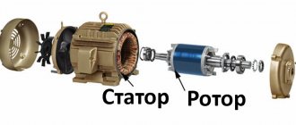
AC machines (ACM) are devices that convert alternating current electrical energy into mechanical energy and vice versa. Like direct current machines (DCM), they have the principle of reversibility and also have moving and stationary parts. The moving part is called the rotor, and the stationary part is called the stator.
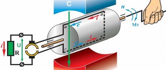
Unlike MPT, in AC machines the most important component is the stationary part, i.e. stator (Fig. 52). This is explained by the fact that it is in the stator winding that the EMF is induced. In a generator, it creates voltage at the terminals of the machine, and in an engine it determines the amount of incoming current and its mechanical characteristics.
Just like in the MPT armature, it is placed in the stator slots. The stator consists of a housing (1), a core (2) and a winding (3). The winding of AC machines is 3-phase and this circumstance is the main feature of AC machines. The fact is that due to the phase shift of the currents relative to each other by 1200, and the spatial separation of the coils in the stator cavity by also 1200, it is possible to create a rotating magnetic field. This fact is illustrated in Fig. 53.
It shows the oscillations of 3 currents in coils A, B, C, the spatial position of which in the stator is marked with three marks on the lower pie charts. These coils are depicted on circles in clockwise order along each of the seven circles, symbolizing the internal cavity of the stator. The black arrow in each circle represents the total magnetic field created by these coils. So, at 00, the total magnetic field is directed upward, towards coil A (the current in it is positive). At 600, i.e. after some time, the largest current - negative sign - appears in coil B and the total magnetic field becomes directed from coil B, which is located in the lower right part of the stator circumference). At 1200, the current in coil C acquires the greatest value - positive - and the total magnetic field turns out to be directed towards coil C, located in the lower left part of the stator circle, etc. An important point in the considered change in the orientation of the magnetic field is that it remains constant in modulus. That is, oscillations of 3 currents in the stator windings lead to uniform rotation of a constant magnetic field in the stator cavity.
The resulting magnetic field (NS) makes one complete revolution in one oscillation period. As is known, industrial 3-phase current has a frequency of 50 Hz, therefore the rotation speed of the magnetic field in the cavity of the MPrT stator is 50x60 = 3000 rpm. Due to the reversibility of AC machines, the converse statement is also true: to create a three-phase current with an AC frequency of 50 Hz, in a machine with 3 coils, the rotation speed of the magnetic field (NS) – i.e. rotor with one pair of poles - should be 3000 rpm. This speed value is the maximum for serial AC machines, but is not the only possible one.
Indeed, if instead of 3 coils in the stator cavity, 6 coils are placed in the alternating order “A-B-C-A-B-C”, then during one period of current oscillation in each phase the induction vector of the total magnetic field will rotate only by 1800, and the field rotation speed will decrease to 1500 rpm. In this case, the rotor of such a machine must have 2 pairs of “NSNS” poles, since after the full period of current oscillations, and the rotor is rotated by 1800, the orientation of the poles must acquire its original configuration. This is only possible if the like poles of the rotor are also at an angle of 1800, and the unlike poles are at an angle of 900.
As a result, with a 3-fold increase in the number of coils, you can get increasingly lower rotation speeds:
| Number of coils |
| Speed rotation (rpm) |
| Number of poles |
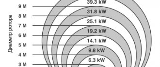
This dependence is used to create engines and generators with reduced rotation speeds. In particular, large power plants (nuclear power plants, hydroelectric power plants) use very powerful and massive alternating current machines. Thus, the mass of the generator rotor at the Sayano-Shushenskaya HPP reaches 900 tons, and the diameter is over 10 meters (10.3 m). Under no circumstances can such a rotor rotate at a speed of 3000 rpm. - its outer edges would have to have a speed several times greater than the speed of a supersonic fighter. To make the rotor rotation speed acceptable for such a massive device - for example, 50 rpm to generate a current with a frequency of 50 Hz - n = 3 * (3000/50) = 180 coils must be placed on the generator stator, and the rotor must have p = 180/3 = 60 pole pairs. Thus, the generator rotor of the Sayano-Shushenskaya hydroelectric power station has 42 poles and a rotation speed of 3000/21 = 142.8 rpm.
Despite the large number of coils, the stator of any MPRT has only 6 output terminals. This means that all the coils are combined into 3 single-phase groups, and in each group (phase) they are connected either in parallel or in series. The sides of the coils are placed in the grooves, and the distances between the sides are chosen so that they are under the adjacent opposite poles of the rotor. This leads to the fact that the EMF induced on the opposite sides of each coil adds up to each other. The actual technology for creating stator windings for AC machines is quite complex and varied. Therefore, within the framework of the number of training hours allocated by the program, we will no longer dwell on this.
As for MPRT rotors, their design is determined by the type of alternating current machine, which, in turn, is determined by the nature of the rotor’s behavior in relation to the rotating magnetic field of the stator. Namely, there are two types of machines: a) synchronous machines; b) synchronous machines.
In synchronous machines, the rotor rotates at the same speed as the magnetic field (hence their name). In asynchronous machines, the speed of rotation of the rotor does not coincide with the speed of rotation of the magnetic field . If it is less than the field rotation speed, then the machine operates as an engine, if higher, as a generator.
Synchronous machines are used in practice both as generators and as motors. In particular, all industrial electricity generators at hydroelectric power stations, nuclear power plants, and thermal power plants are synchronous. Induction machines are mainly used as motors and have become extremely widespread due to the simplicity of their design. It is precisely because of the latter circumstance that asynchronous motors will be considered in more detail. The lower figures show the rotors of synchronous generators (Fig. 54) and asynchronous motors (Fig. 56).
6.2 Asynchronous motors
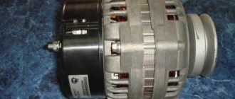
Asynchronous motors (AM, Fig. 55) are widely used in various industries and household appliances due to their simplicity of design. They are widely used in drives of metalworking, woodworking machines, forging and pressing, weaving, sewing, lifting, earth-moving machines, fans, pumps, compressors, centrifuges, and in hand-held power tools.
Asynchronous motors are produced in two versions: a) with a squirrel-cage rotor (CR); b) with a wound rotor (FR). It is the first type of engines that is most widespread. Motors with wound rotor are used less frequently due to the relative complexity and high cost of the design. However, they have better starting and control characteristics and are used to drive conveyors, elevators, crane structures, various industrial mills (coal, cement, etc.), ventilation systems, as well as technical equipment designed for long periods of continuous operation. Below we consider the principle of operation of an IM with a squirrel-cage rotor, which, in general, remains the same in machines with a wound rotor.
The body of the motor with a control valve is cast from aluminum alloy or cast iron, or made welded. Typically, the surface of the housing has a number of longitudinal ribs (Fig. 55) that increase engine cooling. Unlike synchronous machines, whose rotors have their own magnetic poles (Fig. 54), the rotors of asynchronous motors do not have them (Fig. 56). This is explained by the fact that the magnetic field of the rotors of asynchronous motors is not its own, but induced. The main unit of the RC is a system of copper or aluminum rods, tightened together by end rings and forming a “squirrel wheel” type structure. (Fig. 56, “ c ”). This design forms a winding of the rotor, which has the same meaning as the secondary winding of a transformer. The winding is enclosed in a ferromagnetic core - the body of the rotor (Fig. 56, “a”, “b”). The core is made of electrical steel plates and performs the function of a section of the magnetic circuit - the rest of the magnetic circuit includes the stator core. As a result, the entire machine consists of a magnetic core and its two windings - the stator winding and the rotor winding. This means that the engine, with a sufficient degree of correctness, can be considered as a type of transformer.
The latter circumstance is manifested in the use of the design of an asynchronous motor (in the wound-rotor version) as a transformer, which is called an induction voltage regulator. Such a transformer provides a smooth change in voltage in the rotor winding when it is smoothly rotated relative to the stationary stator winding at a given angle - while the rotor itself does not rotate.
An asynchronous motor with a CR operates as follows:
1) when 3-phase voltage is supplied to the stator winding, a current appears in its coils, which generates a rotating magnetic field (see above);
2) the magnetic field, crossing the “squirrel wheel” of the rotor winding, induces in it, according to the law of electromagnetic induction, an eddy electric emf, which, in turn, induces a current and a magnetic field in its rods.
3) the magnetic field of the rotor, interacting with the running magnetic field of the stator, creates a torque on the rotor and drags it along the rotating field of the stator.
At any position and speed of the rotor, its magnetic field always “runs” behind the magnetic field of the stator at the same speed. This means that the rotor poles are in no way tied to the rotor itself and continuously change their orientation in relation to it. Therefore, to express the degree of difference between the rotor rotation speed, n, and the rotation speed of the stator magnetic field, n0, the concept of slip coefficient , s :
If the rotor is stationary, then n=0 and s=1; if the rotor has reached the speed of rotation of the magnetic field, then n= n0 and s=0. Therefore, for all possible rotor rotation speeds, the following inequality is true: 0 < s ≤ 1. The left side of this inequality is strict ( 0< s) - this means that the engine rotor does not conditions cannot rotate exactly at the speed of the magnetic field. This is due to electromagnetic induction, which occurs only with an alternating magnetic field. If the rotor catches up with the magnetic field of the stator winding, then for it it stops changing - the stator field “hangs” above the rotor and the induction of EMF stops. Accordingly, the current, magnetic field and interaction of fields disappear in the rotor - the rotor loses connection with the rotating magnetic field of the stator. Under the influence of friction forces, the rotor will inevitably begin to lag behind the rotating magnetic field. That is why such a motor is called “asynchronous”, i.e. non-synchronous.
Further consideration of the engine is related to the clarification of the internal processes occurring in it at different rotation speeds. These processes have a strong impact on the operating properties and characteristics of IM. In particular, in the high-speed mode of an asynchronous motor, one can distinguish the starting , idle and operating mode.
A. Start mode
In this mode, the fundamental point is the immobility of the rotor ( s = 1 ) - the magnetic field of the stator has a very high rotation speed relative to it and creates a large EMF. This EMF, in turn, creates a large current in the rotor, whose magnetic field, crossing its own fixed rods at the same speed, creates a large self-induction EMF. All this leads to a phase shift between the EMF in the rotor and its current close to 900. In other words, the rotor at the moment of starting has a large inductive reactance.
In Fig. Figure 57 shows a simplified phase diagram of the electrical parameters of the IM at the time of start-up. The main parameter of the diagram is the stator magnetic flux Fs, plotted in a horizontal position. The mains voltage vector is plotted clockwise relative to it (vertically upward), which should lead the stator current and the magnetic flux Fs created by it by 900, since the stator winding is an inductive element of the circuit. Counterclockwise (vertically downwards) the vector of the EMF of the rotor winding is plotted, which always lags behind the magnetic flux that creates it by 900 (the EMF of the stator winding, for the sake of simplicity, is not given). Since the rotor winding current, in turn, lags behind its EMF by an angle close to 900, the overall orientation of the magnetic fluxes on the FR and Fs diagram in phase terms turns out to be close to 1800. On the diagram, their vectors turn out to be oriented in the opposite direction.
On the other hand, the phase shifts of vectors on vector diagrams should repeat the phase shifts between parameters and in real space, if the latter are defined materially in it. Magnetic fluxes, unlike currents and voltages, carry out real rotation in it, and recording instruments must record the same phase shifts between them as in vector diagrams. This, in particular, means that the magnetic fluxes at the moment of start-up rotate in the stator cavity at angles close to 1800 - with the pole orientation as shown in Fig. 57. (a circle with a solid line indicates the rotor, and a circle with a dotted line indicates the stator). In particular, it follows from this that at the moment of start-up, the magnetic poles of the rotor are under the magnetic poles of the stator. This means that the force interaction between them is mainly radial in nature. Real rotation is created only by tangential interactions, which, as follows from the figure, may not be strong enough (if the poles are exactly under each other, then the tangential interactions disappear altogether). This leads to a conclusion confirmed by experience: squirrel-cage asynchronous motors have a weak starting torque.
This is a serious drawback of motors, which in practice has led to their displacement from a number of practical applications and replacement by DC motors, whose starting characteristics are significantly better. Another consequence of this drawback was the emergence of asynchronous motors with a wound rotor, in which this drawback is overcome by transition from a short-circuited winding to an open-phase winding. The phase winding is structurally similar to the stator winding and at the moment of start-up it is closed to external resistance. The appearance of additional resistances in the rotor winding changes the mutual orientation of the magnetic fields (see below) of the stator and rotor at the moment of starting - namely: thanks to resistances , the magnetic poles of the rotor are removed from under the magnetic poles of the stator and the tangential component of their interaction increases sharply. The disadvantage of IMs with phase rotors is that they become more expensive and more difficult to maintain; in particular, after starting, the rheostats must be removed from the rotor circuit, and the winding must be short-circuited.
The starting mode of an IM with a squirrel-cage rotor has another significant drawback - large current values in the stator winding at the moment the motor is turned on. These values may exceed nominal values, i.e. workers, 5 – 15 times. In combination with a weak starting torque, this can lead to engine failure at the moment of starting.
The reason for this lies in the already established antiphase of the magnetic field of the rotor and stator. Since they are spatially directed in the opposite direction at start-up, the total magnetic field should decrease significantly compared to the initial magnetic field of the stator. This should immediately lead to a decrease in the EMF in the stator winding - which, as follows from the vector diagram, basically opposes the mains voltage - and increase the current into the motor. This is exactly what happens in practice: a sharp increase in the current in the stator restores the total magnetic field of the motor to its original value.
In general, since the rotor does not rotate at the moment of start-up, the entire magneto-electric system of the IM in all processes almost exactly reproduces the processes in the transformer and the transformer itself, at this moment, is a transformer. In particular, in the transformer, the same mutual suppression of the magnetic fluxes of the primary and secondary windings occurs (see “Transformers”) and a multiple increase in the operating current - compared to the no-load current - in the primary winding when the secondary is shorted to an external load. An increase in the inrush current of the IM at the time of start-up creates a danger to the integrity of the stator winding and requires in practice additional safety measures - for example, the inclusion of limiting starting rheostats in the IM circuit.
B. Idle mode
This mode is characterized by the absence of load on the motor shaft and, as a result, high rotor speed . The slip coefficient is in the range 0.02 ≤ s ≤ 0.05. This means that the relative speed of rotation (movement) of the rotor and stator is very small, and therefore the EMF induced by the magnetic field of the stator in the rotor windings will also be small.
The smallness of the EMF leads to two consequences: a) the insignificance of the current and magnetic field of the rotor; b) insignificance of the inductive resistance of the rotor winding, xL≈ 0.
The first consequence means a small amount of interaction between the magnetic fields of the rotor and the stator and a small torque - its magnitude is only enough to overcome the insignificant frictional forces in the rotor bearings and maintain its rotation speed at a constant level.
The second consequence means the perpendicular orientation of the magnetic fields of the rotor and stator (Fig. 58). Indeed, on the phase diagram in this mode, the rotor current vector, and therefore its magnetic flux, will almost be in phase with the EMF vector of the rotor winding. This is due to the fact that the rotor resistance will be almost active:
The perpendicularity of the magnetic fields significantly increases the tangential component of the interaction, but in the x/x mode this circumstance does not manifest itself in any way due to the insignificant value of the rotor magnetic field. But this directly affects the amount of current in the stator winding: it becomes very small (3-5% of the nominal). The reason for this is obvious: the stator magnetic field does not encounter opposition from the rotor magnetic field and creates a back emf to the mains voltage even with a small current in the stator winding. This situation reproduces the operating mode of the transformer with the secondary winding open.
The fact that the perpendicular orientation of the magnetic fields of the rotor and stator significantly increases the tangential interactions and, thereby, the torque is used in IMs with a wound rotor. By closing the open rotor winding to external resistance, they sharply increase the active component of its total resistance. As a result, the phase of the current becomes close to the phase of the EMF, and the magnetic field of the rotor turns perpendicular to the magnetic field of the stator. This increases the tangential interaction and makes the starting torque of the engine very large.
C. Operating mode
The operating mode of the blood pressure is intermediate between the modes discussed above . Indeed, the appearance of a load means the occurrence of a braking torque on the motor shaft and a slowdown in the rotor speed. This means that the idle vector diagram should smoothly transform into the start mode vector diagram. It's easy to see how this should manifest itself:
a) in changing the angle of orientation of the magnetic fields of the rotor and stator from 900 to 1800;
b) in increasing the rotor magnetic field from the minimum value at x/x to the maximum value at start-up.
Figure 59 shows graphs of the dependence of the motor torque and its components on the rotor rotation speed. Curve 1 describes the behavior of the tangential component of the interaction, which decreases as the rotor speed slows down. Curve 2 displays the behavior of the interaction forces themselves in modulus, in particular their increase with slowing down of the rotor rotation. As a result, the total torque of the engine acquires a “bell-shaped” shape (Fig. 59, “ 3 ”).
The dependence of the torque, M r, on the rotor rotation speed (more often: on the slip coefficient, s) is called the mechanical characteristic (MC) of an asynchronous motor.
It is easy to see that MX is quite different from the corresponding characteristics of DC motors (Fig. 51 “a”; “b”). The fundamental difference is the presence of a falling section on it, which means a decrease in torque when the speed of rotation of the engine rotor slows down. This fact means that if the counteracting torque exceeds the Mcr value - the maximum torque that the engine can develop - the engine rotation speed will drop to zero, i.e. to s = 1, and the engine - if the torque is not removed - will stop. This factor is unacceptable for a number of applications, which has limited the range of application of squirrel-cage motors.
The normal operating mode of the engine is carried out at Mnom. In practice, it is 2-3 times less than the maximum moment Mkr .
Differences from DC machines
The fundamental design difference lies in the location of the winding. In AC systems it covers the stator, and in DC machines it covers the rotor. In both groups, electric motors differ in the type of current excitation - mixed, parallel and series. Today, AC and DC machines are used in industry, agriculture and in the domestic sphere, but the first option is more attractive in terms of its performance. AC generators and motors benefit from improved design, reliability and high energy efficiency.
The use of devices operating on direct current is common in areas where the requirements for precision control of operating parameters come to the fore. These can be traction mechanisms of transport, processing machines and complex measuring instruments. In terms of performance, DC and AC machines have high efficiency, but with different possibilities for technical and design adjustment to specific application conditions. Working with constant current gives you more control over speed, which is important when servicing servo motors and stepper motors.
Purpose
According to the operational characteristics of the machine Iper. superior to analogues on Ipost, therefore they are preferred, their advantages:
- technological design;
- reliability;
- high energy output.
At the same time, they are inferior to IDC devices. precise regulation of operating parameters. Therefore, the engines of electric vehicles, complex measuring instruments and some processing machines operate at Ipost. In most cases, AC machines are used. Asynchronous motors are simple and are used most often and in a wide variety of areas.
Asynchronous MPT device
For the technical basis of this device in the form of a rotor and stator, sheet steel is used, which is covered with an insulating oil-rosin layer on both sides before assembly. In low-power machines, the core can be made of electrical steel without additional coating, since the insulator in this case is the natural oxide layer on the metal surface. The stator is fixed in the housing, and the rotor is fixed on the shaft. In high-power asynchronous AC machines, the rotor core can also be attached to the housing rim with a sleeve mounted on the shaft. The shaft itself must rotate on bearing shields, which are also fixed to the base of the housing.
The outer surfaces of the rotor and the inner surfaces of the stator are initially provided with slots to accommodate the winding conductors. In the stator of AC machines, the winding is often three-phase and connected to the corresponding 380 V network. It is also called primary. The rotor winding is made similarly, the ends of which usually form a connection in a star configuration. Slip rings are also provided, through which a rheostat for adjustment or a three-phase starting element can additionally be connected.
It is also important to note the parameters of the air gap, which serves as a damper zone that reduces noise, vibration and heating during operation of the device. The larger the car, the larger the gap should be. Its size can vary from one to several millimeters. If it is structurally impossible to leave enough space for the air zone, then an additional cooling system for the installation is provided.
Types of electric motors
Today there are quite a lot of electric motors of different designs and types. They can be divided by type of power supply :
- Alternating current , operating directly from the mains.
- Direct current , which operate from batteries, rechargeable batteries, power supplies or other direct current sources.
According to the principle of operation:
- Synchronous , in which there are windings on the rotor and a brush mechanism to supply electric current to them.
- Asynchronous , the simplest and most common type of motor. They do not have brushes or windings on the rotor.
A synchronous motor rotates synchronously with the magnetic field that rotates it, while an asynchronous motor rotates slower than the rotating magnetic field in the stator.
Operating principle and design of an asynchronous electric motor
in the housing of an asynchronous motor (for 380 Volts there will be 3 of them), which create a rotating magnetic field. Their ends are connected to a special terminal block for connection. The windings are cooled thanks to a fan mounted on the shaft at the end of the electric motor.
The rotor , which is one piece with the shaft, is made of metal rods that are closed to each other on both sides, which is why it is called short-circuited. Thanks to this design, there is no need for frequent periodic maintenance and replacement of current supply brushes, reliability, durability and reliability increase many times over.
As a rule, the main cause of failure of an asynchronous motor is wear of the bearings in which the shaft rotates.
Principle of operation. In order for an asynchronous motor to work, it is necessary that the rotor rotates slower than the electromagnetic field of the stator, as a result of which an EMF is induced (an electric current arises) in the rotor. An important condition here is that if the rotor rotated at the same speed as the magnetic field, then, according to the law of electromagnetic induction, no EMF would be induced in it and, therefore, there would be no rotation. But in reality, due to bearing friction or shaft load, the rotor will always rotate more slowly.
The magnetic poles constantly rotate in the motor windings, and the direction of the current in the rotor constantly changes. At one point in time, for example, the direction of currents in the stator and rotor windings is depicted schematically in the form of crosses (current flows away from us) and dots (current towards us). The rotating magnetic field is shown as a dotted line.
For example, how does a circular saw work ? It has the highest speed without load. But as soon as we start cutting the board, the rotation speed decreases and at the same time the rotor begins to rotate more slowly relative to the electromagnetic field and, according to the laws of electrical engineering, an even larger EMF begins to be induced in it. The current consumed by the motor increases and it begins to operate at full power. If the load on the shaft is so great that it stops, then damage to the squirrel-cage rotor may occur due to the maximum value of the EMF induced in it. That is why it is important to select an engine with suitable power. If you take a larger one, then the energy costs will be unjustified.
The rotation speed of the rotor depends on the number of poles. With 2 poles, the rotation speed will be equal to the rotation speed of the magnetic field, equal to a maximum of 3000 revolutions per second at a network frequency of 50 Hz. To reduce the speed by half, it is necessary to increase the number of poles in the stator to four.
A significant disadvantage of asynchronous motors is that they can adjust the shaft rotation speed only by changing the frequency of the electric current. And so it is not possible to achieve a constant shaft rotation speed.
Operating principle of asynchronous MPT
In this case, the three-phase winding is connected to a symmetrical network with three-phase voltage, as a result of which a magnetic field is formed in the air gap. Regarding the armature winding, special measures are taken to achieve a harmonic spatial field distribution for the damper gap, which forms a system of rotating magnetic poles. According to the principle of operation of an alternating current machine, a magnetic flux is formed at each pole, which crosses the contours of the winding, thereby provoking the generation of electromotive force. A three-phase current is induced in the three-phase winding, providing torque to the motor. Against the background of the interaction of the rotor current with magnetic fluxes, an electromagnetic force is formed on the conductors.
If the rotor, under the influence of an external force, is set in motion, the direction of which corresponds to the direction of the magnetic field flows of the alternating current machine, then the rotor will begin to overtake the rate of rotation of the field. This occurs when the stator speed exceeds the rated synchronous frequency. At the same time, the direction of movement of electromagnetic forces will be changed. This creates a braking torque with reverse action. This operating principle allows the machine to be used as a generator operating in the mode of delivering active power to the network.
Operating principle
When voltage is applied to the stationary stator windings, it creates a magnetic field in the stator. If AC voltage is applied, the magnetic flux created by it changes. So the stator produces a change in the magnetic field, and the rotor receives magnetic fluxes.
Thus, the rotor of the electric motor receives this stator flux and therefore rotates. This is the basic principle of operation and sliding in asynchronous machines. From the above, it should be noted that the stator magnetic flux (and its voltage) must be equal to the alternating current to rotate the rotor, so that an induction machine can only operate on alternating current.
Operating principle of an asynchronous motor
When such motors act as a generator, they will directly generate alternating current. In the case of such operation, the rotor is rotated by external means, say a turbine. If the rotor has some residual magnetism, that is, some magnetic properties that are retained by the type of magnet inside the material, then the rotor creates an alternating flux in the stationary stator winding. So it is the stator windings that will receive the induced voltage using the principle of induction.
Induction generators are used in small shops and households to provide additional power support and are the least expensive due to easy installation. Recently, they have been widely used by people in those countries where electric machines lose power due to constant voltage drops in the power supply network. Most of the time, the rotor is rotated by a small diesel engine coupled to an asynchronous alternating voltage generator.
Design and principle of operation of synchronous MPTs
In terms of design and stator location, a synchronous machine is similar to an asynchronous one. The winding is called an armature and is made with the same number of poles as in the previous case. The rotor has an excitation winding, the energy supply of which is provided by slip rings and brushes connected to a direct current source. By source we mean a low-power generator-exciter installed on one shaft. In an AC synchronous machine, the winding acts as a primary magnetic field generator. During the design process, designers strive to create conditions so that the inductive distribution of the excitation field on the stator surfaces is as close to sinusoidal as possible.
At increased loads, the stator winding forms a magnetic field with rotation in the direction of the rotor with a similar frequency. In this way, a single rotation field is formed, in which the stator field will influence the rotor. This design of AC machines allows them to be used as electric motors, if a three-phase current supply to the synchronous winding is initially provided. Such systems create conditions for coordinated rotation of the rotor at a frequency corresponding to the stator field.
The principle of operation and design of alternating current electrical machines. Synchronous machines
AC machines are somewhat different in design from DC machines. Every machine has two main parts: a stationary part called a stator and a rotating part called a rotor. Unlike DC machines, AC machines usually have an armature winding on the stator, and an excitation winding on the rotor. Instead of a collector, the rotor has insulated rings through which current is conducted into the field winding.
Synchronous are those AC machines in which the rotation speed of the rotor and the frequency of the alternating current in the windings change simultaneously and proportionally to each other, i.e. synchronously. With a change in the frequency of the current, such machines simultaneously (synchronously) change the number of revolutions.
As a rule, synchronous machines have direct current from an external source passing through the excitation winding. Synchronous machines are reversible, i.e. can work as generators and electric motors. The design of a synchronous motor is almost no different from the design of a synchronous generator.
Since on naval vessels the AC networks are powered by three-phase synchronous generators, we will dwell on their structure and operating principle.
The armature winding of a three-phase synchronous generator is located in the stator and consists of three separate windings - phases shifted relative to each other by 120° (1/3 of the period) in such a way that the induced emf. in each phase reached its maximum 1/3 of the period after the maximum emf. adjacent phase. The field winding is placed on the rotor and the power source for it can be a small direct current generator (exciter) mounted on the same shaft as the synchronous generator, or a battery.
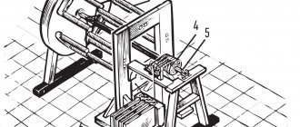
The stator windings are connected to each other by a star or triangle, while three wires (three contacts) extend from the stator windings into the external circuit. A longitudinal section of a three-phase alternating current synchronous generator with an exciter is shown in Fig. 172.
The rotor consists of pole cores 1, field winding coil 2, supplied with direct current through slip rings 5. The stator consists of active armature steel 3, which serves as a magnetic circuit, and a frame 6, which serves to fasten the armature steel and install the machine on the foundation. The active steel of the armature is made from sheets of special steel with a thickness of 0.5 or 0.35 mm. The sheets are insulated on both sides with a special varnish. Winding 4 is placed in grooves stamped into the stator steel.
In Fig. 173, a shows the placement of the three-phase stator winding (on one fourth of its part), and diagrams b and c show the connection of the stator winding into a triangle and a star. When connected into a triangle, the beginning of the first phase I is connected to the end of II, the beginning of II is connected to the end of III, and the beginning of III is connected to the end of I.
When the stator windings are connected by a star, the ends of all phases are connected to one point, called zero, and the beginnings of all phases remain free and an external circuit is connected to them, into which the electrical energy generated by the generator is supplied.
Synchronous three-phase generators are currently the main sources of electrical energy at both coastal and ship power stations of any capacity. In recent years, synchronous generators in which the excitation winding is powered by stator current, previously rectified using rectifiers, have become widespread on marine vessels. At the same time, the excitation circuit of these machines ensures such a change in the excitation current that the voltage at the generator terminals is maintained almost constant. Such generators are called synchronous generators with self-excitation and self-regulation of voltage.
The design of a synchronous motor is not fundamentally different from the design of a synchronous generator. In order for the synchronous generator to operate in motor mode, it is necessary to turn off the prime mover and supply three-phase current from the network to the phase windings of the stator.
In this case, the generator will become a synchronous electric motor consuming current. Passing through the phase windings, the alternating three-phase current creates a rotating magnetic field, which, interacting with the rotor electromagnet, drags it in the direction of its rotation. As a result, the rotor will rotate at the same speed as the rotating magnetic field. In this case, the generator will not stop, even if you give it a load by connecting it to some mechanism. This is the essence of the operation of a synchronous electric motor.
The rotor speed of a synchronous motor is regulated by changing the frequency of the network current, and changing the direction of rotation of the rotor is done by switching any two phases, i.e. mutual reconnection of two supply wires.
Similar articles
- Ship power stations
- Asynchronous motors
- Transformers
- Maintenance of DC electrical machines
- DC motors
- DC Generators
- Operating principle, design of DC electrical machines
- Work and current power
- Joule-Lenz law, physical law
- Electric circuit and electrical resistance
Rating 0.00 (0 Votes)
Salient-pole and non-salient-pole synchronous machines
The main difference between salient pole systems is the presence of protruding poles in the design, which are attached to special shaft protrusions. In typical mechanisms, fixation is performed using T-shaped tail fasteners to the crosspiece rim or shaft through a sleeve. In the design of low-power AC machines, the same problem can be solved by bolted connections. The winding material is strip copper, which is wound onto an edge, insulated with special gaskets. The terminals with poles in the grooves house the winding rods for starting. In this case, a high resistivity material like brass is used. The winding contours at the ends are welded to the short-circuiting elements, forming common rings for a short circuit. Salient-pole machines with a power potential of 10-12 kW can be made in the so-called reversed design, when the armature rotates and the poles of the inductor remain stationary.
For non-salient pole machines, the design is based on a cylindrical rotor made of steel forging. The rotor contains grooves for forming an excitation winding, the poles of which are designed for high rotation speeds. However, the use of such a winding in electrical machines with high-power alternating current is impossible due to the high degree of rotor wear under harsh operating conditions. For this reason, even in medium-power installations, high-strength components made from solid forgings based on chromium-nickel-molybdenum or chromium-nickel steels are used for rotors. In accordance with the technical requirements for strength, the maximum diameter of the working part of the rotor of a non-salient-pole synchronous machine cannot be higher than 125 cm. This explains the unusual form factor of the rotor with an elongated body, although there are restrictions on this parameter associated with increased vibrations for too long elements. The maximum rotor length is 8.5 m. Non-salient-pole units used in industry include various turbogenerators. With their help, in particular, they connect the operating torques of steam turbines with thermal power plants.
Features of vertical hydro generators
A separate class of salient-pole synchronous MPTs provided with a vertical shaft. Such installations are connected to hydraulic turbines and selected according to the power of the flows being served according to the rotation frequency. Most AC machines of this type are low-speed, but have a large number of poles. Among the critical working components of a vertical hydraulic generator, we can note the thrust bearing and thrust bearing, which bear the load from the rotating parts of the engine. In particular, the pressure from the flow of water that acts on the turbine blades is also applied to the thrust bearing. In addition, a brake is provided to stop rotation, and the working structure also contains guide bearings that absorb radial forces.
At the top of the machine, along with the hydraulic generator, auxiliary units can be placed - for example, a generator exciter and a regulator. By the way, the latter is an independent alternating current machine with windings and poles of permanent magnets. This installation provides power to the motor to provide the automatic governor function. In large vertical hydrogen generators, the exciter can be replaced by a synchronous generator, which, together with exciter units and mercury rectifiers, provides energy supply to power devices that serve the working process of the main hydro generator. The machine's vertical shaft configuration is also used as a drive mechanism for high-power hydraulic pumps.
Collector MPT
The presence of a collector unit in the MPT design is often determined by the need to perform the function of converting the rotational speed in the electrical connection of different-frequency circuits on the rotor and stator windings. This solution allows you to provide the device with additional operational properties, including automatic regulation of operating parameters. AC commutator machines that are connected to three-phase networks receive three brush fingers in each double-pole segment. The brushes are connected to each other in a parallel circuit using jumpers. In this sense, commutator MMTs are similar to direct current electric motors, but differ from them in the number of brushes used on the poles. In addition, the stator in this system may have several additional windings.
The closed armature winding when using a commutator with three-phase brushes will be a three-phase complex winding with a delta connection. During the rotation of the armature, each phase of the winding maintains a constant position, but the sections alternately move from one phase to another. If an AC commutator machine uses a six-phase set of brushes shifted by 60° relative to each other, then a six-phase winding is formed with a polygon connection. On the brushes of a multiphase machine with a commutator group, the current frequency is determined by the rotation of the magnetic flux with respect to the stationary brushes. The direction of rotation of the rotor can be either counter or coordinated.
Application of MPT
Today, MPTs are used wherever the generation of mechanical or electrical energy is required in one form or another. Large productive units are used in the maintenance of engineering systems, power stations and lifting and transport units, and low-power units are used in ordinary household appliances from fans to pumps. But in both cases, the purpose of alternating current machines is to generate sufficient energy potential. Another thing is that the design differences, the implementation of the internal configuration of the stator and rotor, as well as the control infrastructure are of fundamental importance.
Although the general design of the MPT for a long time retains the same set of functional components, increasing requirements for the operation of such systems force developers to introduce additional monitoring and control elements. At the present stage of technological development, especially in the context of the use of alternating current machines in the industrial sector, it is difficult to imagine the operation of such engines and generators without high-precision means of regulating operating parameters. For this, a variety of control methods are used - pulse, frequency, rheostat, etc. The introduction of automation into the regulatory infrastructure is also a characteristic feature of modern MPT operation. The control electronics are connected to the power plant on one side, and on the other to software controllers, which, according to a given algorithm, give commands to set specific parameters for the operation of the mechanism.