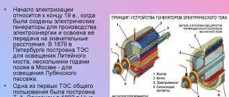
§ 51. Reception and transmission of alternating electric current. Transformer -
Questions. 1. What electric current is called alternating? With the help of what simple experience can it be obtained?
An alternating current is a current that periodically changes over time in magnitude and direction. Alternating current can be obtained using an induction coil, a galvanometer and a magnet. By periodically moving the magnet up and down inside the coil, you will notice that the galvanometer plate deviates in one direction or the other.
2. Where is alternating electric current used?
Alternating electric current is used in everyday life and industry.
3. On what phenomenon is the operation of the currently most common alternating current generators based?
The operation of alternating current generators is based on the phenomenon of electromagnetic induction.
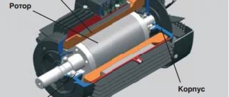
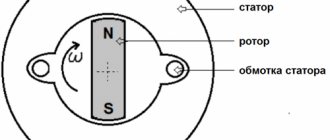
4. Tell us about the structure and operating principle of an industrial generator.
An industrial alternating current generator consists of a stator and a rotor. The stator is fixed, and the rotor rotates. The rotor and stator are wrapped in a special way with copper wire. The rotor is supplied with a constant electric current and is thus an electromagnet. When the rotor rotates, the magnetic field it creates also rotates. In this case, an alternating magnetic flux penetrates the stator winding and an alternating electric current arises in it.
5. What drives the generator rotor at a thermal power plant? at a hydroelectric power station?
Steam and water turbine.
6. Why are multi-pole rotors used in hydrogen generators?
To create a current of standard frequency, because The rotation speed of water turbines is low.
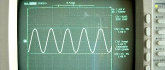
7. What is the standard frequency of industrial current used in Russia and many other countries?
The standard frequency in Russia is 50 Hz, in the USA - 60 Hz.
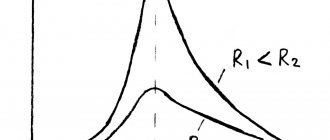
8. By what physical law can energy losses in power lines be determined?
According to the Joule-Lenz law: Q= I 2 Rt, where Q is the energy spent on heating the wires, I is the effective value of the alternating current in the circuit, R is the resistance of the wires, t is time.
9. What should be done to reduce electricity losses during transmission?
From the Joule-Lenz law it follows that for this it is necessary to reduce the circuit resistance R and the current I.
10. Why, when the current strength decreases, is its voltage increased by the same amount before being fed into the power line?
In order not to reduce the current power P= UI. Transmitting low-power current over long distances is not economically viable (it is necessary to build expensive power lines, stations and substations, and as a result, not all consumers will be able to use electricity).
11. Tell us about the structure, principle of operation and application of transformers.
Industrial frequency - current
Industrial current frequency (50 Hz) is the most unfavorable for humans.
As the frequency increases, the value of the non-releasing current changes slightly. With decreasing frequency, the value of the non-releasing current increases and at a frequency equal to zero (direct current), it becomes approximately 3 times larger. The values of the fibrillation current at frequencies of 50 - 100 Hz are equal; with an increase in frequency to 200 Hz, the current increases approximately 2 times, and at a frequency of 400 Hz - almost 4 times. [1] At an industrial frequency of the current in the coil of 50 Hz, the thickness of the sheets is usually 0 35 - 0 5 mm. At higher frequencies, the thickness of the sheets decreases to 0 02 - 0 05 mm. 0 5 - 4 5% silicon (Si) is added to the magnetic circuit material; such an additive significantly increases the electrical resistivity of the material and has little effect on its magnetic properties. [2]
At an industrial frequency of current in the coil of 50 Hz, the thickness of the sheets is usually 0 35 - 0 5 mm. At higher frequencies, the thickness of the sheets decreases to 0 02 - 0 05 mm. [3]
At industrial frequency current, the hopper and tray 6 located in it make 100 oscillations per second. With a change in voltage, the traction force of the electromagnets changes, and, consequently, the amount of movement of the armature and spring. [5]
At an industrial frequency of current in the coil of 50 Hz, the thickness of the sheets is usually 0 35 - 0 5 mm. At higher frequencies, the thickness of the sheets decreases to 0 02 - 0 05 mm. 0 5 - 4 5% silicon (Si) is added to the magnetic circuit material; such an additive significantly increases the electrical resistivity of the material and has little effect on its magnetic properties. [6]
For induction soldering, high- and industrial-frequency current settings, as well as special ones, are used. [8]
The method covers arc discharges of direct and alternating industrial frequency currents, pulsed and high-frequency discharges, as well as glow, quiet, corona and high-frequency torch discharges. [10]
The operation of protective devices in case of damage is mainly determined by the periodic components of the industrial frequency of currents / p and voltages t / p acting on the relay, and the phase shifts fr between them. [eleven]
The operation of protective devices during a short circuit is in most cases determined by the periodic components of the industrial frequency of currents / p and voltages UP supplied to the relay, as well as the phase shifts fr between them. Below, for the purpose of simplification, we consider the relationships that characterize them for an unloaded line with one-sided supply (Fig. 1.24) at the initial moment of damage. Two-way power supply, loads and other additional factors are taken into account only for some typical cases. [13]
The operation of protective devices during a short circuit is in most cases determined by the periodic components of the industrial frequency currents / p and voltages Up supplied to the relay, as well as the phase shifts pp between them. Below, for the purpose of simplification, we consider the relationships that characterize them for an unloaded line with one-sided supply (Fig. 1.24) at the initial moment of damage. Two-way power supply, loads and other additional factors are taken into account only for some typical cases. [15]
Source