AC period and frequency
This term “alternating electric current” should be understood as a current that changes over time in any way, in accordance with the concept of “variable quantity” introduced into mathematics.
However, the term “alternating electric current” came into electrical engineering to mean an electric current varying in direction (as opposed to an electric current in a constant direction), and therefore in magnitude, since it is physically impossible to imagine changes in electric current in direction without corresponding changes in magnitude . The movement of electrons in a wire, first in one direction and then in the other, is called one alternating current oscillation. The first oscillation is followed by a second, then a third, etc. When the current oscillates in the wire around it, a corresponding oscillation of the magnetic field occurs.
The time of one oscillation is called a period and is designated by the letter T. The period is expressed in seconds or in units of fractions of a second. These include: a thousandth of a second - a millisecond (ms), equal to 10 -3 s, a millionth of a second - a microsecond (μs), equal to 10 -6 s, and a billionth of a second - a nanosecond (ns), equal to 10 -9 s.
An important quantity characterizing alternating current is frequency. It represents the number of oscillations or the number of periods per second and is denoted by the letter f or F. The unit of frequency is the hertz, named after the German scientist G. Hertz and abbreviated as Hz (or Hz). If one complete oscillation occurs in one second, then the frequency is equal to one hertz. When ten oscillations occur within a second, the frequency is 10 Hz. Frequency and period are reciprocals:
At a frequency of 10 Hz, the period is 0.1 s. And if the period is 0.01 s, then the frequency is 100 Hz.
Frequency is the most important characteristic of alternating current. Electrical machines and AC devices can only operate normally at the frequency for which they are designed. Parallel operation of electric generators and stations on a common network is only possible at the same frequency. Therefore, in all countries, the frequency of alternating current produced by power plants is standardized by law.
In an AC electrical network, the frequency is 50 Hz. The current flows fifty times per second in one direction and fifty times in the opposite direction. One hundred times per second it reaches an amplitude value and one hundred times becomes equal to zero, that is, it changes its direction one hundred times when passing through the zero value. Lamps connected to the network dim a hundred times a second and flash brighter the same number of times, but the eye does not notice this, thanks to visual inertia, i.e. the ability to retain the impressions received for about 0.1 s.
When calculating with alternating currents, the angular frequency is also used; it is equal to 2pif or 6.28f. It should be expressed not in hertz, but in radians per second.
At the accepted industrial current frequency of 50 Hz, the maximum possible number of generator revolutions is 50 rpm (p = 1). Turbogenerators are built for this number of revolutions, i.e. generators driven by steam turbines. The speed of hydraulic turbines and the hydraulic generators they drive depends on natural conditions (primarily pressure) and varies widely, sometimes decreasing to 0.35 - 0.50 rpm.
The number of revolutions has a great influence on the economic indicators of the machine - overall dimensions and weight. Hydrogenerators with several revolutions per second have an outer diameter 3 - 5 times larger and weigh many times more than turbogenerators of the same power with n = 50 rps. In modern alternating current generators, their magnetic system rotates, and the conductors in which the emf is induced are placed in a stationary part of the machine.
Alternating currents are usually divided by frequency. Currents with a frequency of less than 10,000 Hz are called low frequency currents (LF currents). These currents have a frequency corresponding to the frequency of various sounds of the human voice or musical instruments, and are therefore otherwise called audio frequency currents (except for currents with a frequency below 20 Hz, which do not correspond to audio frequencies). In radio engineering, LF currents are widely used, especially in radiotelephone transmission.
However, the main role in radio communications is played by alternating currents with a frequency of more than 10,000 Hz, called high-frequency currents, or radio frequencies (HF currents). The units used to measure the frequency of these currents are kilohertz (kHz), equal to a thousand hertz, megahertz (MHz), equal to a million hertz, and gigahertz (GHz), equal to a billion hertz. Otherwise, kilohertz, megahertz and gigahertz are denoted by kHz, MHz, GHz. Currents with a frequency of hundreds of megahertz and higher are called ultra-high or ultra-high frequency currents (microwave and UHF).
Radio stations operate using alternating HF currents with a frequency of hundreds of kilohertz and higher. In modern radio engineering, currents with a frequency of billions of hertz are used for special purposes, and there are instruments that make it possible to accurately measure such ultrahigh frequencies.
Source
Period and frequency
If we carefully examine the graph of the flow of periodic alternating current, we can establish the following rule: at the same time intervals of equal duration, oscillatory movements are displayed on the graph with 100% accuracy.
Such time intervals are called periods and are displayed on paper with the symbol “T”.
The frequency of an electric current, which has a variable value, represents a certain number of oscillatory movements repeated within a given unit of time.
To form a unified approach to the designation of electric current parameters, frequency is considered a mathematical quantity equal to the number of periods per second. The unit of measurement is hertz (Hz). AC frequency is one of the most important parameters to characterize the technological process. It is important to understand that numerous electrical machines, devices and alternating current installations can operate effectively only if, when power is supplied to the device, the frequency that corresponds to the technical characteristics and parameters of the device is provided.
The current standard frequency used in AC power is 50 Hz. This means that the electric current will be directed in one direction 50 times within one second and exactly the same amount in the other. The speed of industrial electric generators is synchronized with the economic indicators of the machines, including their weight and overall dimensions.
Alternating (sinusoidal) current and the main quantities characterizing it.
Alternating current (AC) - electric current
, which changes in magnitude and direction over time or, in a particular case, changes in magnitude while maintaining its direction in the electrical circuit unchanged.
In everyday life, alternating, sinusoidal current is used for power supply.
Sinusoidal current is a current that changes over time according to a sinusoidal law (Figure 1):
Picture 1
The maximum value of the function is called amplitude. It is denoted using a capital (capital) letter and a lowercase letter m - the maximum value. Eg:
- the current amplitude is denoted by lm;
- voltage amplitude Um.
Period T is the time it takes to complete one complete oscillation.
Frequency f is equal to the number of oscillations per second (the unit of frequency f is hertz (Hz) or s -1)
f = 1/T
Angular frequency ω (omega) (unit of angular frequency - rad/s or s -1)
ω = 2πf = 2π/T
The argument of the sine, i.e. ( ωt + Ψ ), is called the phase . The phase characterizes the state of oscillation (numerical value) at a given time t.
Any sinusoidally varying function is determined by three quantities: amplitude, angular frequency ( ω ) and initial phase Ψ (psi)
In the CIS countries and Western Europe, sinusoidal current installations with a frequency of 50 Hz, accepted as standard in the energy sector, are most widespread. In the US, the standard frequency is 60 Hz. The frequency range of practically used sinusoidal currents is very wide: from fractions of a hertz, for example in geological exploration, to billions of hertz in radio engineering.
Sinusoidal currents and EMF of relatively low frequencies (up to several kilohertz) are obtained using synchronous generators (they are studied in the course of electrical machines). Sinusoidal currents and EMF of high frequencies are obtained using tube or semiconductor generators (discussed in detail in the radio engineering course and in less detail in the TOE course). A source of sinusoidal EMF and a source of sinusoidal current are designated on electrical diagrams in the same way as sources of constant EMF and current, but they are designated e and j (or e(t) and j(t)).
General concept of alternating current[edit]
Since alternating current in the general case changes in an electrical circuit not only in magnitude, but also in direction, one of the directions of alternating current in the circuit is considered conditionally positive, and the other, opposite to the first, conditionally negative. In accordance with this, the magnitude of the instantaneous value of the alternating current is considered positive in the first case, and negative in the second case.
Alternating current is an algebraic quantity, its sign is determined by the direction in which the current flows in the circuit at the given moment in time - positive or negative.
The amount of alternating current corresponding to a given moment in time is called the instantaneous value of alternating current
.
The maximum instantaneous value of the alternating current that it reaches during its change is called the current amplitude
.
A graph of alternating current versus time is called an alternating current diagram.
Expanded diagram of alternating sinusoidal current
The figure shows an expanded diagram of alternating current
, changing over time in magnitude and direction. On the horizontal axis, time intervals are plotted on a certain scale, and on the vertical axis, current values are plotted upward - from the starting point - positive, down - negative. The part of the expanded current diagram located above the time axis characterizes the change in positive values over time, and the part located below the time axis characterizes the change in negative values.
At the initial moment of time, the current is zero. Then it grows over time in a positive direction, at the moment of time it reaches its maximum value, after which it decreases in value and at the moment of time it becomes equal to zero. Then, having passed through the zero value, the current changes its sign to the opposite, that is, it becomes negative, then increases in absolute value, then reaches a maximum at , after which it decreases and becomes equal to zero.
What is the frequency of alternating current formula
§ 50. Basic quantities characterizing alternating current
Variable e. d.s., alternating voltage, as well as alternating current are characterized by period, frequency, instantaneous, maximum and effective values. Period.
The time during which the variable e.
d.s. (voltage or current) makes one complete change in magnitude and direction (one cycle), called period
.
The period is designated by the letter T
and is measured in seconds.
If one complete change in the variable e. d.s. takes place in 1/50 sec
, then the period of this e.
d.s. equal to 1/50 sec
.
Frequency.
The number of complete changes in the variable e.
d.s. (voltage or current) performed in one second is called frequency
.
Frequency is symbolized by f
and is measured in hertz (
Hz
).
When measuring high frequencies, the units kilohertz ( kHz
) and megahertz (
MHz
) are used;
1 kHz
= 1000
Hz
, 1
MHz
= 1000
kHz
, 1
MHz
= 1,000,000
Hz
= 10 6
Hz
. The higher the frequency of the alternating current, the shorter the period. Thus, frequency is the reciprocal of period.
Example.
The duration of one period of alternating current is 1/500
sec
.
Determine the frequency of the current. Solution . One complete change in alternating current occurs in 1/500 sec
. Therefore, 500 such changes will occur in one second. Based on this, the frequency
The longer the period of alternating current, the lower its frequency. Thus, the period is the reciprocal of the frequency, i.e.
Example.
The current frequency is 2000
Hz
(2
kHz
).
Determine the period of this alternating current. Solution . In 1 second,
2000 complete alternating current changes occur. Consequently, one complete change in current - one period occurs in 1/2000 of a second. But based on this period
Angular frequency.
When a coil rotates in a magnetic field, one revolution corresponds to 360°, or 2π radians.
(1 rad
= 57° 17′ 44″; π = 3.14.) If, for example, a coil
makes one revolution T
= 3
seconds
Accordingly, the angular speed of rotation of this turn is expressed in rad/sec
and is determined by the ratio
This quantity is called the angular frequency
and is denoted by the letter ω. Thus,
Since the AC frequency
then, substituting this value of
f
into the expression for the angular frequency, we get:
Angular frequency ω, expressed in rad/sec
, greater than the current frequency
f
, expressed in hertz, 2π times.
If the alternating current frequency f
= 50
Hz
, then the angular frequency
ω = 2πf
= 2 · 3.14 · 50 = 314
rad/sec
In various fields of technology, alternating currents of various frequencies are used. At power plants in the USSR, generators are installed that produce alternating electromotive force, the frequency of which is f
= 50
Hz
.
In radio engineering and electronics, alternating currents with frequencies ranging from tens to many millions of hertz are used. Instantaneous and maximum values.
The magnitude of variable electromotive force, current, voltage and power at any time is called
the instantaneous values
of these quantities and is denoted by lowercase letters (
e, i, u, p
), respectively.
The maximum value
(amplitude) of the variable e.
d.s. (or voltage or current) is called the greatest value that it reaches in one period. The maximum value of the electromotive force is denoted E
m, voltage -
U
m, current -
I
m. In Fig. 51 it is clear that the variable e. d.s. reaches its value twice in one period.
Effective value.
Electric current flowing through wires heats them regardless of its direction.
In this regard, heat is generated not only in direct current circuits, but also in electrical circuits through which alternating current flows. If an alternating electric current flows through a conductor with resistance r ohm
, then a certain amount of heat is released every second.
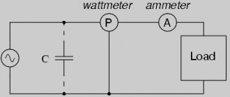
This amount of heat is directly proportional to the maximum value of the alternating current. It is possible to select a direct current that, flowing through the same resistance as the alternating current, would release an equal amount of heat. In this case, we can say that on average the action (efficiency) of alternating current in terms of the amount of heat generated is equal to the action of direct current. The effective (or effective) value of alternating current is such a direct current force that, flowing through equal resistance and in the same time as alternating current, releases the same amount of heat. Electrical measuring instruments (ammeter, voltmeter) connected to the alternating current circuit measure the effective value of current and voltage, respectively. For sinusoidal alternating current, the effective value is 1.41 times less than the maximum, i.e., times.
Similarly, the effective values of alternating electromotive force and voltage are also 1.41 times less than their maximum values.
From the measured effective values of alternating current, voltage or electromotive force, their maximum values can be calculated:
E
m =
E
1.41;
U
m =
U
1.41;
I
m =
I
1.41; (55)
Example.
A voltmeter connected to the circuit terminals shows the effective voltage
U
=
127
V. Calculate the maximum value (amplitude) of this alternating voltage. Solution . The maximum voltage value is several times greater than the effective voltage , so
U
m =
U
· = 127 · 1.41 = 179.07
V
To characterize each variable electromotive force, alternating voltage or alternating current, it is not enough to know the period, frequency and maximum value.
Phase. Phase shift.
When comparing two or more variable sinusoidal quantities (emf, voltage or current), it is also necessary to take into account that they can change unequally over time and reach their maximum value at different times.
If in an electrical circuit the current changes over time in the same way as the e. d.s., i.e. when the electromotive force is zero and the current in the circuit is zero, and with increasing e. d.s. to a positive maximum value, the current strength in the circuit simultaneously increases and reaches a positive maximum value, and further, when e. d.s. decreases to zero and the current simultaneously becomes zero, etc., then in such a circuit the alternating electromotive force and the alternating current are in phase. In Fig. Figure 52 shows the moments of rotation of two conductors in a magnetic field and graphs of changes in e. d.s. in the wires. Wire 1
and wire
2
are shifted by an angle φ = 90°.
When the magnetic flux crosses, a variable e appears in each of the wires. d.s. When the electromotive force in wire 2
is zero, in wire
1
it will be maximum.
2
in the wire .
d.s. gradually increases and reaches its maximum value at time t
1, and in wire
1
the induced e.
d.s. gradually decreases and at the same moment in time is equal to zero. Thus, induced e.g. in wires. d.s. do not coincide in phase, but are shifted relative to each other in phase by 1/4 of a period or by an angle φ = 90°. In addition, e. d.s. in wire 1
it reaches its maximum earlier than e.
d.s. in wire 2
, and therefore it is believed that the electromotive force
e
1 is ahead in phase e.
d.s. e
2 or e.
d.s. e
2 lags in phase from e.
d.s. e
1. When calculating alternating current circuits, the phase shift between alternating voltage and current is of great practical importance.
AC current and voltage parameters
The magnitude of alternating current, like voltage, constantly changes over time. Quantitative indicators for measurements and calculations use their following parameters:
Period
T
is the time during which one complete cycle of current change occurs in both directions relative to zero or the average value.
Frequency
f
is the reciprocal of the period, equal to the number of periods in one second.
One cycle per second is one hertz (1 Hz). Frequency f =
1
/T
Cyclic frequency
ω
- angular frequency equal to the number of periods in
2π
seconds.
ω = 2πf = 2π/T
Typically used in sinusoidal current and voltage calculations. Then, within the period, one can not consider frequency and time, but make calculations in radians or degrees. T = 2π = 360°
The initial phase
ψ
is the value of the angle from zero (
ωt
= 0) to the beginning of the period. Measured in radians or degrees. Shown in the figure for the blue sinusoidal current graph.
The initial phase can be a positive or negative value, respectively to the right or left of zero on the graph.
Instantaneous value
- the magnitude of voltage or current measured relative to zero at any selected time
t
.
i = i(t); u = u(t)
The sequence of all instantaneous values in any time interval can be considered as a function of the change in current or voltage over time. For example, a sinusoidal current or voltage can be expressed by the function:
i = Iampsin(ωt); u = Uampsin(ωt)
Taking into account the initial phase:
i = Iampsin(ωt + ψ); u = Uampsin(ωt + ψ)
Here Iamp
and
Uamp
are the amplitude values of current and voltage.
Amplitude value
— maximum modulo instantaneous value for the period.
Iamp = max|i(t)|; Uamp = max|u(t)|
Can be positive or negative depending on its position relative to zero. Often, instead of the amplitude value, the term amplitude
current (voltage) - maximum deviation from zero value.
Average value
(avg) - defined as the arithmetic mean of all instantaneous values over the
period T.
The average value is a constant component of DC
voltage and current. For sinusoidal current (voltage), the average value is zero.
Average rectified value
— arithmetic mean of the modules of all instantaneous values for the period.
For a sinusoidal current or voltage, the rectified average value is equal to the arithmetic mean over the positive half-cycle.
Root Mean Square (rms) - Defined as the square root of the arithmetic mean of the squares of all instantaneous values over a period.
For sinusoidal current and voltage amplitude Iamp
(
Uamp
) root mean square value is determined from the calculation:
Root mean square is the current, effective value, most convenient for practical measurements and calculations. It is an objective quantitative indicator for any form of current. In an active load, the alternating current does the same work during the period as a direct current equal in magnitude to its root-mean-square value.
Current frequency
The invention of electricity brought humanity to a new frontier of development. Technological progress relied on two directions of movement using electricity. In one case, direct current was used, in the second - alternating current. The introduction of electricity sources and power consumers resulted in a hundred-year war between adherents of the two types of energy. In the end, those who promoted the idea of widespread use of its variable form won.
General concept of alternating current
Unlike electrons constantly moving in one direction, alternating current changes both direction and value several times per unit of time. Changes occur according to a harmonic law. If you observe a similar signal using an oscilloscope, you can see a picture in the form of a sine wave.
Relative to the ordinate axis OY, the current changes its direction from positive to negative and does this periodically. Therefore, its instantaneous value in the first position is considered positive, in the second - negative.
Important! Since alternating current is an algebraic quantity, we can talk about its sign of charge only for a specific instantaneous value, depending on the direction in which it flows at that moment.
Instantaneous power in an alternating current circuit with active resistance.
With variable voltage and current values, the rate of conversion of electrical energy in the receiver, i.e. its power, also changes. Instantaneous power is equal to the product of instantaneous voltage and current values: p = Umsinωt * Imsinωt = UmImsin2ωt
From trigonometry we find
A more clear idea of the nature of the change in power in a circuit is given by a graph in a rectangular coordinate system, which is constructed after multiplying the ordinates of the voltage and current curves corresponding to a number of values of their common argument - time t. The dependence of power on time is a periodic curve (Fig. 13.2). If the time axis t is raised according to the drawing by the amount p = Pm√2 = UmIm√2, then relative to the new axis t' the power graph is a sinusoid with double frequency and an initial phase of 90°:
Thus, in the original coordinate system, the instantaneous power is equal to the sum of the constant value Р = UmIm√2 and the variable р':
p = P + p'
Analyzing the instantaneous power graph, it is easy to notice that the power remains positive during the period, although the current and voltage change their sign. This is achieved due to the phase coincidence of voltage and current.
The constancy of the power sign indicates that the direction of the flow of electrical energy remains unchanged during the period, in this case from the network (from the energy source) to the receiver with resistance R, where the electrical energy is irreversibly converted into another type of energy. In this case, electrical energy is called active.
We advise you to study LED lighting in the apartment and interior decoration elements
If R is the resistance of the conductor, then, in accordance with the Lenz-Joule law, electrical energy in it is converted into heat.
Periodic alternating current
One that, while changing, manages to return to its original value at equal time intervals and at the same time goes through the entire cycle of its transformations, is called periodic. It can be traced on a sinusoid displayed on the oscilloscope screen.
It can be seen that at regular intervals the graph repeats without changes. These intervals are designated by the letter T and are called periods. The frequency with which a certain number of similar periods fits into a unit of time is the frequency of an alternating current.
It can be calculated using the AC frequency formula:
Where:
- f – frequency, Hz;
- T – period, s.
Frequency is equal to the number of cycles per second and has a unit of 1 hertz (Hz).
Attention! The SI unit of frequency is named after Heinrich Hertz. 1 hertz (Hz, Hz) = 1 s-1. Multiple and submultiple units, expressed by standard SI prefixes, are applicable to it.
Frequency standards
In order to ensure coordination of the operation of sources of alternating electricity, transmission systems, reception and operation of electrical consumers, frequency standards are applied. Frequency used in electrical engineering in some countries:
- 50 Hz – countries of the former USSR, the Baltic states, European countries, Australia, North Korea and others;
- 60 Hz is the standard adopted in the USA, Canada, the Dominican Republic, Taiwan, the Cayman Islands, Cuba, Costa Rica, South Korea and some other countries.
In Japan, both frequencies are used. Eastern regions (Tokyo, Sendai, Kawasaki) use 50 Hz. Western regions (Kyoto, Hiroshima, Nagoya, Okinawa) use a frequency of 60 Hz.
For your information. The railway infrastructure of Austria, Norway, Germany, Switzerland and Sweden still uses the 16.6 Hz frequency.
Rotation speed: formula
The number of repetitions of any events or their occurrence in one timer unit is called frequency. This physical quantity is measured in hertz – Hz (Hz). It is denoted by the letters ν, f, F, and is the ratio of the number of repeating events to the period of time during which they occurred.
When an object rotates around its center, we can talk about such a physical quantity as rotation frequency, the formula:
Where:
- N – number of revolutions around an axis or in a circle,
- t is the time during which they were completed.
In the SI system it is denoted as – s-1 (s-1) and is referred to as revolutions per second (rps). Other units of rotation are also used. When describing the rotation of planets around the Sun, they speak of revolutions in hours. Jupiter rotates once every 9.92 hours, while the Earth and Moon rotate every 24 hours.
Alternating sinusoidal current
This is the current that changes periodically over time, and its changes obey the sinusoid law. This is the elementary movement of electric charges, therefore it cannot be further decomposed into simple currents.
The type of formula for such an alternating current is:
Where:
- Im – amplitude;
- sinωt – phase of sinusoidal current, rad.
Here ω = const is called the angular frequency of alternating electricity, and the angle ωt is in direct time dependence.
Knowing the frequency f of the original current, you can calculate its angular frequency using the expression:
Here 2π is the value of the central angle of the circle expressed in radians:
- T = 2 π radians = 3600;
- T/2 = π = 1800;
- T/4 = π/2 = 900.
If we express 1 rad in degrees, it will be equal to 57°17′.
What is angular velocity of alternating current
§ 50. Basic quantities characterizing alternating current
Variable e. d.s., alternating voltage, as well as alternating current are characterized by period, frequency, instantaneous, maximum and effective values. Period.
The time during which the variable e.
d.s. (voltage or current) makes one complete change in magnitude and direction (one cycle), called period
.
The period is designated by the letter T
and is measured in seconds.
If one complete change in the variable e. d.s. takes place in 1/50 sec
, then the period of this e.
d.s. equal to 1/50 sec
.
Frequency.
The number of complete changes in the variable e.
d.s. (voltage or current) performed in one second is called frequency
.
Frequency is symbolized by f
and is measured in hertz (
Hz
).
When measuring high frequencies, the units kilohertz ( kHz
) and megahertz (
MHz
) are used;
1 kHz
= 1000
Hz
, 1
MHz
= 1000
kHz
, 1
MHz
= 1,000,000
Hz
= 10 6
Hz
. The higher the frequency of the alternating current, the shorter the period. Thus, frequency is the reciprocal of period.
Example.
The duration of one period of alternating current is 1/500
sec
.
Determine the frequency of the current. Solution . One complete change in alternating current occurs in 1/500 sec
. Therefore, 500 such changes will occur in one second. Based on this, the frequency
The longer the period of alternating current, the lower its frequency. Thus, the period is the reciprocal of the frequency, i.e.
Example.
The current frequency is 2000
Hz
(2
kHz
).
Determine the period of this alternating current. Solution . In 1 second,
2000 complete alternating current changes occur. Consequently, one complete change in current - one period occurs in 1/2000 of a second. But based on this period
Angular frequency.
When a coil rotates in a magnetic field, one revolution corresponds to 360°, or 2π radians.
(1 rad
= 57° 17′ 44″; π = 3.14.) If, for example, a coil
makes one revolution T
= 3
seconds
Accordingly, the angular speed of rotation of this turn is expressed in rad/sec
and is determined by the ratio
This quantity is called the angular frequency
and is denoted by the letter ω. Thus,
Since the AC frequency
then, substituting this value of
f
into the expression for the angular frequency, we get:
Angular frequency ω, expressed in rad/sec
, greater than the current frequency
f
, expressed in hertz, 2π times.
If the alternating current frequency f
= 50
Hz
, then the angular frequency
ω = 2πf
= 2 · 3.14 · 50 = 314
rad/sec
In various fields of technology, alternating currents of various frequencies are used. At power plants in the USSR, generators are installed that produce alternating electromotive force, the frequency of which is f
= 50
Hz
.
In radio engineering and electronics, alternating currents with frequencies ranging from tens to many millions of hertz are used. Instantaneous and maximum values.
The magnitude of variable electromotive force, current, voltage and power at any time is called
the instantaneous values
of these quantities and is denoted by lowercase letters (
e, i, u, p
), respectively.
The maximum value
(amplitude) of the variable e.
d.s. (or voltage or current) is called the greatest value that it reaches in one period. The maximum value of the electromotive force is denoted E
m, voltage -
U
m, current -
I
m. In Fig. 51 it is clear that the variable e. d.s. reaches its value twice in one period.
Effective value.
Electric current flowing through wires heats them regardless of its direction.
In this regard, heat is generated not only in direct current circuits, but also in electrical circuits through which alternating current flows. If an alternating electric current flows through a conductor with resistance r ohm
, then a certain amount of heat is released every second.
This amount of heat is directly proportional to the maximum value of the alternating current. It is possible to select a direct current that, flowing through the same resistance as the alternating current, would release an equal amount of heat. In this case, we can say that on average the action (efficiency) of alternating current in terms of the amount of heat generated is equal to the action of direct current. The effective (or effective) value of alternating current is such a direct current force that, flowing through equal resistance and in the same time as alternating current, releases the same amount of heat. Electrical measuring instruments (ammeter, voltmeter) connected to the alternating current circuit measure the effective value of current and voltage, respectively. For sinusoidal alternating current, the effective value is 1.41 times less than the maximum, i.e., times.
Similarly, the effective values of alternating electromotive force and voltage are also 1.41 times less than their maximum values.
From the measured effective values of alternating current, voltage or electromotive force, their maximum values can be calculated:
E
m =
E
1.41;
U
m =
U
1.41;
I
m =
I
1.41; (55)
Example.
A voltmeter connected to the circuit terminals shows the effective voltage
U
=
127
V. Calculate the maximum value (amplitude) of this alternating voltage. Solution . The maximum voltage value is several times greater than the effective voltage , so
U
m =
U
· = 127 · 1.41 = 179.07
V
To characterize each variable electromotive force, alternating voltage or alternating current, it is not enough to know the period, frequency and maximum value.
Polyphase AC
To start and operate many industrial devices and electrical equipment, not one phase, but several are required. In this regard, concepts such as two-phase and three-phase alternating currents are considered.
Three-phase current
This type of electricity is used in a three-phase system, which includes three single-phase circuits. The circuits have an EMF of variable nature of the same frequency. These emfs are phase shifted relative to each other by ϕ = Т/3 = 2π/3. Such a system is called three-phase current, and the circuit is called a phase.
The generation, conversion, delivery and consumption of alternating electric current mainly occurs through a three-phase power supply system.
Two-phase current
Back in 1888, Nikola Tesla described how a two-phase network could be used in practice, and proposed the design of a two-phase motor he developed. Such networks began to be used at the beginning of the 20th century. They consisted of two circuits.
There, the circuit voltages were shifted in phase by 900. Each phase included two wires; two-phase generators had two rotors, also structurally rotated at an angle of 900.
Important! Such networks made it possible to soft start two-phase electric motors from almost zero torque. While starting a single-phase asynchronous motor requires an additional starting winding or starting system.
What currents are there?
Energy is required to power electrical devices and electrical equipment. Direct and alternating currents are a way of transferring energy from one point to another using conductors.
Important! The main difference between them is the nature of the movement of charged particles. Direct current flows uniformly in one direction, while alternating current constantly changes direction at a given speed or frequency. The main consequence of this is voltage polarity.
Constant
Direct current is characterized by a constant indicator of the polarity of charged particles. Since direct current maintains a constant polarity, it is important to pay attention to how the device is connected - incorrectly connecting the device to the network will most likely damage it. A good example is battery-powered devices - they are always marked with markings to ensure they are connected correctly. Otherwise, the equipment simply will not work, as it will not receive power.
Important! When using direct current, the voltage reading can vary greatly depending on the device used. Typical rated voltages of autonomous power supplies are 1.5V, 3.7V, 6V, 9V,12V, 24V, etc.
You might be interested in this: Features of soldering
Changing the direction of current
Variable
With alternating current, the polarity constantly switches between positive and negative values. With such a characteristic of the force field, the voltage will constantly change, and the polarity in this case does not have any effect on the performance of the network. That is why any household electrical device can be plugged into the network without thinking about the position of the plug in the outlet, that is, about maintaining the correct polarity.
The main reason for the widespread use of alternating current is the relative ease and efficiency of increasing or decreasing voltage. This is achieved using transformers, and the number of changes in quantitative indicators is determined by the number of windings.
Important! The same transformation is allowed for a constant value, but this phenomenon is not effective for its application in practice. Also, this is another, additional reason why alternating current is used in the household network.
Phases in the battery
Although lower voltages are easier to generate, higher voltages incur less losses when transmitted over distances. Therefore, before supplying consumers, the alternating voltage is increased to several hundred kilovolts. But, once the electricity reaches its destination, it drops to 110 or 220 volts. The fact is that the variable indicator has two established standard voltages that are used all over the world: 220V and 110V. Frequency plays a decisive role in electrical engineering, and devices designed for a voltage of 110V will not operate on a 220V network.
AC generation
In addition to standard generators, inverters and phase splitters are used to produce alternating current.
Inverter
This is a device with the help of which direct current is converted into alternating current. During this process, the output voltage also changes. The device circuit is an electronic generator of a sinusoidal pulse voltage of a periodic nature. There are options for inverters that operate with a discrete signal. Inverters are used for autonomous power supply of equipment from constant voltage batteries.
Phase splitter
Another way to get multiple phases from a signal is to split it into several phases. This is done using a phase splitter. Forced processing of digital or analog signals is used both in radio electronics and power electrical engineering.
To supply power to three-phase asynchronous motors, a phase splitter based on them is used. To do this, the windings of a three-phase motor are connected not by a star, but in a different way. Two coils are connected to each other in series, the third is connected to the midpoint of the second winding. The motor is started as a single-phase one, after acceleration, an EMF is induced in its third winding.
Interesting. In the case of phase splitting using this method, the phase shift between windings 2 and 3 is not 1200, as it should ideally be, but 900.
Generating alternating current[edit]
The simplest alternating current generator: if a flywheel with several pairs of permanent magnets installed in it is rotated around a wire coil wound on a magnetic core made of transformer steel, then a sinusoidal EMF will be induced in the coil (conventionally shown as one turn), and when a load is connected, an alternating current will appear in the electrical circuit current. Used on vehicles (mopeds, light motorcycles, snowmobiles, jet skis, as well as outboard boat motors), works in conjunction with a rectifier and voltage regulator (see Magdino)
.
Main article: Alternator
The operating principle of an alternating current generator is based on the law of electromagnetic induction - the induction of an electromotive force in a rectangular loop (wire frame) located in a uniform rotating magnetic field.
The electromotive force of an alternator is determined by the formula:
, Where
— number of turns;
- magnetic induction of the magnetic field in volt-seconds per square meter ( T
,
Tesla
);
— the length of each of the active sides of the circuit in meters;
— angular velocity of the sinusoidal electromotive force, in this case equal to the angular velocity of rotation of the magnet in the circuit;
— phase of the sinusoidal electromotive force.
The frequency of the alternating current generated by the generator is determined by the formula:
, Where
— frequency in hertz;
— number of rotor revolutions per minute;
— number of pairs of poles.
According to the number of phases, alternating current generators are:
- three-phase generators are the main type of powerful industrial generators; See also three-phase power supply system, three-phase motor, three-phase alternating current automobile generator
. - single-phase generators, used, as a rule, in low-power gasoline power plants, built into internal combustion engines of mopeds, light motorcycles, snowmobiles, jet skis, and outboard boat engines; See also capacitor motor, single-phase motor
. - two-phase generators are much less common compared to single-phase and three-phase. See also two-phase electrical network, two-phase motor
.
Modified sine wave generated by an inverter.
Invertersedit
Direct current can be converted to alternating current using an inverter.
It should be noted that inexpensive inverter models have a non-sinusoidal alternating current output, usually rectangular pulses or a modified sine wave. To produce a sinusoidal current, the inverter must have a master oscillator (usually a specialized microcircuit that generates a sinusoidal electrical signal, which then controls the operation of thyristor or transistor electronic switches.
Phase splitteredit
Three-phase current can be obtained from single-phase current using a phase splitter. These electric machines are used, in particular, on electric locomotives such as VL60, VL80.
AC networks
Based on their purpose and application, these networks can be classified as follows:
- general systems: power supply for industrial, transport, agricultural and domestic facilities;
- autonomous networks: supplying mobile and stationary autonomous entities.
General three-phase alternating current networks are built according to a four-wire circuit, where three wires are “phase” and the fourth is “zero”. Transformer substations are built according to a scheme with a solidly grounded neutral. Long-distance transmission is carried out at high voltage, which is then reduced at substations to a voltage of 0.4 kV and distributed to consumers.
Household objects are connected using a single-phase circuit. In this case, two wires are required: “phase” and “neutral”.
Alternating current
The term explains the characteristics of one of the types of electric current, which constantly changes over time. Changes occur both in absolute values and in direction. As a special case, changes are possible only in magnitude, while maintaining the direction of the oscillatory motion in the electrical circuit unchanged. This current (alternating) is widely used in the lighting network of households, residential buildings, as well as at numerous industrial facilities.
If with direct current the electrons always move in one direction, then alternating current is characterized by multiple changes not only in direction, but also in values (several times per unit time). All such changes occur in accordance with one law - harmonic. In a picture displayed using an oscilloscope, such a picture can be seen in the form of a clear, geometrically accurate sinusoid
It is important to understand that alternating current is an algebraic quantity, therefore its sign can only be indicated taking into account a specific instantaneous value (taking into account the direction in which the electrons are moving at a particular moment in time)
Relationship between frequency and operation of electrical equipment
Current frequency is one of the parameters of electricity that affects the stable operation of electrical installations and equipment. When supplying energy to the consumer, this parameter is strictly controlled, just like voltage.
The thread of relationship is expressed by the formula for the nominal number of revolutions per minute for rotating machines. Efficiency (coefficient of performance) is inherent in the very design of the units. It is maximum at:
Where:
- n – number of rpm;
- f – frequency;
- p – number of pairs of poles.
The number of revolutions of the generator turbine is directly related to the frequency of the generated alternating current; the resulting frequency is responsible for the optimal rotation mode of the consumer's electric motor. When the frequency in the network decreases, the machine speed is reduced automatically. The shaft is overloaded and the engine suffers.
At the same time, the production line into which it transfers rotational energy also undergoes changes in operation:
- the speed of the conveyor changes, which entails a failure of the technological process and ultimately defects;
- the power and rotation speed of pumps and fans are reduced, which leads to unstable operation of the systems in which they are installed;
- a 1% decrease in frequency in the power system leads to a drop in the total power at the load to 2%.
Frequency meters are used to monitor this important electrical parameter.
Attention! A decrease in frequency by 10-15% causes the productivity of mechanisms even at the power plant itself to drop to zero. At a current frequency in the network of 50 Hz (the critical value is 45 Hz), an avalanche decline occurs.
What are the phases in the current?
Only alternating current can be multiphase. There are 3 different phases in total, and they are all shifted 120 degrees relative to each other. Each power station produces 4 wires: 3 phase and one for grounding, which is common to all three. The power plant produces three different phases of alternating current simultaneously, and these three phases are shifted strictly at a certain angle.
Phase arrangement
Why three phases? Why not one, two or four? In 1-phase and 2-phase power supplies, a phenomenon occurs when the sine wave crosses the zero mark 120 times per second. With three-phase power, at any given moment one of the three phases is approaching peak. Thus, high-power 3-phase motors (used in industry) and other devices such as 3-phase welding equipment have a uniform power output.
You may be interested in this Features of cables and wires
Important! Four phases will not significantly improve the situation, but it will add a fourth wire, which will increase the complexity of many works and maintenance, so 3 phases is the generally accepted and optimal value.
Three-phase
Three-phase power is a common method of generating, transmitting and distributing variable power. It is a type of multiphase system and the most common method used by electrical networks around the world to transmit energy. It is also used to power large motors and when heavy loads are encountered.
A three-phase circuit is generally more economical than an equivalent two-wire single-phase circuit at the same line voltage and grounding because less conductor material is used to transmit a given amount of electrical energy.
Interesting fact: Polyphase power systems were invented by Galileo Ferrari, Mikhail Dolivo-Dobrovolsky, Jonas Wenström, John Hopkinson and Nikola Tesla back in the late 1880s, and the basic operating principles are still used today.
Particle movement
Two-phase
Two-phase electrical power was the only AC power distribution system available in the early 20th century. At that time, two circuits were used, and the voltage phases differed by a quarter of a cycle, that is, by 90°. Typically, circuits used four wires, two for each phase. Less commonly used were three wires with a common core, but of a larger diameter. Some two-phase generators of yesteryear had two complete rotor assemblies with physically offset windings to provide two-phase power.
Today, two-phase power supply has become widespread in everyday life, since every consumer - resident of an apartment or private house - has a certain number of connection points for low-power household appliances.
Important! With the standard operation of the most common household appliances, a two-phase electrical circuit fully satisfies the needs of residential property owners.
The turbine generator plants at Niagara Falls, built in 1895, were the largest in the world at that time and were precisely two-phase machines. However, ultimately, three-phase systems replaced the hopelessly outdated and inefficient original units for generating and transmitting energy. There are currently few industrial two-phase distribution systems left in the world, such as those in Philadelphia, Pennsylvania.
You may be interested in this Features of lumens and luxes
Two-phase current
High frequency currents
HDTV – this is their abbreviation; they are used for melting metals and hardening the surface of metal products. HDTV are currents with a frequency of more than 10 kHz. Induction furnaces use HDTV by placing a conductor inside a winding through which the HDTV is passed. Under their influence, eddy currents arising in the conductor heat it up. By adjusting the strength of the HDTV, the temperature and heating rate are controlled.
Interesting. The metal to be melted can be suspended in a vacuum using a magnetic field. It does not require a crucible (a special ladle for heating). This is how very pure substances are obtained.
Advantages of using HDTV in different cases:
- rapid heating during forging and rolling of metal;
- optimal temperature conditions for soldering or welding parts;
- melt even very refractory alloys;
- cooking in microwave ovens;
- Darsonvalization in medicine.
HDTV is obtained using installations that include an oscillating circuit or electric machine generators. The stator and rotor of the generators have teeth on the sides facing each other. Their mutual movement generates a pulsation of the magnetic field. The greater the product of the number of rotor teeth and its rotation frequency, the greater the output frequency.
Pulsation period and frequency
The frequency of alternating current may have another name - ripple. The pulsation period is the time of a single pulsation.
Cycle intensity
For an electrical network with a frequency of 50 Hz, the pulsation period will be:
If necessary, knowing this dependence, you can calculate the frequency from the cycle time.
The danger of multi-frequency charges
Both direct and alternating current at certain values pose a danger to humans. Up to 500 V the difference in safety is in the ratio 1:3 (42 V DC to 120 V AC).
At values above 500 V, this ratio levels out, with constant electricity causing burns and electrolysis of the skin, while changing electricity causes convulsions, fibrillation and death. Here the pulsation frequency is of great importance. The most dangerous frequency range is from 40 to 60 Hz. Further, with increasing frequency, the risk of damage decreases.
The frequency of alternating electricity is an important parameter. It affects not only the operation of consumer electrical installations, but also the human body. By changing the frequency of electrical oscillations, it is possible to change technological processes in production and the quality of the generated energy.
Determining Frequency and Period
Fluctuations in the flow of charges occur cyclically, according to a sinusoidal law. The length of one such cycle, expressed in seconds, is the alternating current period (T).
The frequency of the current is determined by the number of oscillatory cycles in 1 second. In other words, it is the rate at which the current changes direction. The letter symbol representing frequency is f.
The relationship between frequency and period, expressed mathematically, is determined by the formula:
f = 1/T.
The inverse relationship is also true:
T = 1/f.
AC period
In calculations, the frequency of alternating current is measured in hertz (Hz). If the current completes 1 oscillatory cycle per second, then f = 1 Hz.
Important! Fifty oscillatory cycles in 1 second correspond to 50 Hz. This is the industrial frequency of electric current in Russia.
Sometimes angular frequency is used in calculations:
ω = 2πf,
The unit of measurement for this indicator is rad/s.
1 radian = 360°/2π.
Some common frequency ranges:
- 50-60 Hz – current frequency in the power system (60 Hz is used, for example, in the USA);
- 1-20 kHz (kilohertz) – variable frequency drives;
- 16 Hz -20 kHz – audio frequencies (range of human hearing);
- 3 kHz-3000 GHz (gigahertz) – radio frequencies.