At a certain combination of signal frequency and reactance, a resonance is formed in the electrical circuit. Radio amateurs use it to tune into a specific transmitting station. Power line designers make special calculations to prevent voltage surges and emergency situations. The information presented below will help you successfully solve practical problems based on the features of this phenomenon.
When there is resonance in the AC circuit, the signal amplitude increases sharply
Reasons for resonance
The classic example of a commander ordering marching soldiers to “go out of step” in front of a bridge clearly demonstrates the essence of this phenomenon. If such precautions are not used, vibrations can increase to a critical value, even leading to structural failure. To obtain maximum amplitude, swing the swing in a certain rhythm. The examples given demonstrate a significant increase in the result when the frequencies of the external influence and the system itself coincide.
Electrical resonance is no different in its principles from its mechanical counterparts. It is formed when the frequencies of the external signal and the circuit coincide. The functions of energy storage devices are performed by reactive inductive and capacitive elements. Losses (gradual decrease in amplitude) provide electrical resistance of the circuit, which is similar to the coefficient of friction.
Principle of current resonance
Resonance - what is it?
To create the necessary conditions for electroresonance, it is necessary to create a parallel circuit with three typical components:
- resistance (R);
- capacity (C);
- inductance (L).
The circuit is connected to a power source with voltage (U)
At a certain frequency, the total drains through the reactive elements (IL, Ic) become significantly greater than the source current (I). This phenomenon is called current resonance.
Resonance Characteristics
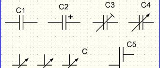
Capacitor in AC circuit
This phenomenon occurs when the reactive components of the circuit are identical. This distribution allows for uniform circulation of the magnetic and electrical components of energy (through inductance and capacitor, respectively). Such a circuit is called “oscillatory” by analogy with a mechanical pendulum.
When a certain resonant frequency (w) is reached in a parallel (series) circuit, the impedance is maximum (minimum). Accordingly, when the electrical resistance changes, the current decreases (increases).
Resonance of currents and voltages
Mechanical resonance
A parallel circuit is used to create current resonance. To fulfill the conditions noted above, equal values of reactive conductivities (BL and Bc) are selected. As the frequency increases, the total resistance of the circuit increases, which is accompanied by a decrease in current.
Graph of changes in current and conductivity, formulas for calculations
Similar functional components are installed in the series resonant circuit. This circuit, upon reaching the resonant frequency, reduces the resistance, which is accompanied by a significant increase in the voltage on the reactive components compared to the electromotive force of the power source.
Voltage resonance in an AC circuit: graph, electrical diagram and calculation formula
Lesson 44 Voltage resonance
2015-04-01 3201
The series connection diagram of active resistance, inductor and capacitor is shown in Fig. 44.1.
Rice. 44.1. Diagram of series connection of active resistance, inductor and capacitor
When three elements R, L, C are connected in series, the vector diagram looks like this: the current vector in circuit I is laid out horizontally, the voltage vector across the active resistance UR coincides with it, the voltage vector across the inductance UL is directed upward, and the voltage vector across the capacitance UC is directed downward .
Fig.44.2. Vector diagram of voltages for a series connection of an active resistance, an inductor and a capacitor.
If the voltage drop across the inductive reactance is greater than that across the capacitive reactance, then the resulting vector will lead the current vector by some angle φ. In this case, the circuit is said to be inductive. (see Fig. 44.3.)
Fig.44.3. Vector diagram of a circuit with an inductive nature.
If the voltage drop across the capacitive reactance is greater than that across the inductive one, then the resulting voltage vector will lag behind the current vector by some angle φ. In this case, the circuit is said to be capacitive in nature. (see Fig. 44. 4.)
Fig.44.4. Vector diagram of a circuit with capacitive character.
In general, the voltage equation in the circuit will be equal to:
and the resistance equation:
A feature of the series connection of active resistance, capacitance and inductance is the possibility of voltage resonance.
Let's imagine that in a circuit with active resistance, capacitance and inductance connected in series, the current frequency increases from frequency f1 to frequency f2. (See Fig. 44.5.)
Fig.44.5. Changes in reactance with changes in current frequency.
As the frequency of the current in the circuit increases, the capacitive reactance decreases and the inductive reactance increases. At some value of current frequency, capacitive reactance becomes equal to inductive reactance. This frequency is called resonant. Phenomena occurring in a circuit with R, L, C connected in series at a resonant frequency are called voltage resonance.
At resonance, the voltage across the capacitor UC is equal to the voltage across the inductance UL. But since they are in antiphase to each other, their sum is zero.
The condition for resonance is the equality of reactance XL = XC or
From here the value of the resonant frequency is determined
When a circuit is not tuned to resonance, its impedance is given by:
, at resonance, when XL = XC, the total resistance of the circuit will be equal to:
Thus, the total resistance of the circuit at resonance turns out to be equal to the active resistance.
Reducing the total resistance of the circuit leads to the fact that the current strength in it increases.
In the vector diagram at resonance (see Fig. 44. 6), the voltage vectors on the reactive elements are equal to each other and directed in opposite directions. i.e., they are shifted in phase relative to each other by an angle of 180 degrees. The phase angle between current and voltage in the network is zero.
Fig.44.6. Vector diagram at voltage resonance.
Fig.44.7. Change in current in a circuit at resonance.
Source
RLC circuit
To clarify the processes, it is necessary to study the features of the components of a typical RLC circuit. If a capacitor is connected to an AC source, the voltage on its windings will change in the same way as the original signal. For calculations, use the concept of capacitance Xc , which is determined by the formula:
Xc = 1/2π * f * C,
Where:
- f – frequency;
- C – capacity.
As the frequency increases, the capacitance increases and the current decreases:
I = U/ Xc.
This element performs certain restrictive functions. However, it does not dissipate energy into heat like conventional electrical resistance R.
For your information. For simplicity, the ideal capacity is considered here. In reality, every electronic component creates an active resistance to current, which in certain situations is accompanied by heating.
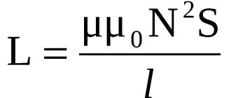
To calculate the influence of the inductive component, the following formulas are used:
- XL = 2π * f * L;
- I=U/XL;
- I = U/2π * f * L.
When the coil is connected to a power source, a magnetic field is generated that prevents the passage of current. The formulas demonstrate the direct dependence of resistance on frequency and inductance value (L).
Capacitor in AC circuit
Direct current cannot exist in a circuit containing a capacitor. The movement of electrons is prevented by a dielectric located between the plates. But alternating current can exist in such a circuit, as evidenced by experience with a lamp (see figure below).
Even if such a circuit is actually open, but if alternating current flows through it, the capacitor is either charged or discharged. The current flowing when the capacitor is recharged heats the lamp filament, and it begins to glow.
Let's find how the current strength changes in a circuit containing only a capacitor, if the resistance of the wires and plates of the capacitor can be neglected (see figure above). The voltage across the capacitor will be equal to:
u=φ1−φ2=qC..
Let's take into account that the voltage across the capacitor is equal to the voltage at the ends of the circuit:
qC..=Umaxcos.ωt
Consequently, the charge of the capacitor changes according to the harmonic law:
q=CUmaxcos.ωt
Then the current strength, which is the time derivative of the charge, will be equal to:
i=q´=−CUmaxsin.ωt=CUmaxcos.(ωt+π2..)
Consequently, current fluctuations are ahead of voltage fluctuations across the capacitor by π2.. (see graph below). This means that at the moment when the capacitor begins to charge, the current is maximum and the voltage is zero. After the voltage reaches its maximum, the current becomes zero, etc.
The amplitude of the current is:
Imax=UmaxCω
Let's assume that:
1Cω..=XC
We will also use the effective values of current and voltage. Then we get that:
Definition
I=UXC..
The value of XC, equal to the inverse product of the cyclic frequency and the electrical capacitance of the capacitor, is called capacitance . The role of this quantity is similar to the role of active resistance R in Ohm's law.
Note that during the quarter period when the capacitor is charged to its maximum voltage, energy enters the circuit and is stored in the capacitor in the form of electric field energy. In the next quarter of the period (when the capacitor is discharged), this energy is returned to the network.
Example No. 1. The maximum charge on the capacitor plates of the oscillatory circuit is qmax=10−6 C. The amplitude value of the current in the circuit is Imax = 10−3 A. Determine the period of oscillation (neglect losses due to heating of the conductor).
According to the law of conservation of energy, the maximum value of the energy of the electric field of the capacitor is equal to the maximum value of the magnetic field of the coil:
q2max2C..=LI2max2..
From here:
LC=q2maxI2max..
√LC=qmaxImax..
T=2π√LC=2πqmaxImax..=2·3.1410−610−3..≈6.3·10−3 (s)
Electrical resonance
To fully study (apply) the phenomenon, it is necessary to take into account the total resistance of the circuit (Z). Together with losses, it can be expressed by the following formula when connecting functional elements in series:
Z = √ R2 + (2π * f * L - 1/2π * f * C)2.
According to Ohm's law:
I = U/Z = U/ √ R2 + (2π * f * L - 1/2π * f * C)2.
If the equality of the reactive components is maintained, the resistance decreases while the current increases. If this condition is met, it is easy to calculate the resonant frequency ( Fres ):
- 2π * f * L = 1/2π * f * C;
- Fres = 1/2π * √ L*C.
Resonance of voltages reaching maximum amplitude
You can obtain the highest amplitude in a series circuit by changing the following parameters:
- inductance;
- containers;
- frequencies.
The values of individual components are determined using the formulas discussed above. So, the capacity value can be calculated as follows:
C = 1/ f2 * L.
If the reactive components are significantly greater than the active resistance, an increase in voltage can be obtained at the terminals of the capacitor or coil compared to the source.
Resonance of currents through reactive elements
In a parallel circuit one operates with the concepts of reactive conductivities (BL and Bc). As in the previous example, to create a resonant mode it is necessary to ensure that these parameters are equal. An additional condition is the coincidence of frequencies (source and circuit). The current at resonance will pass only through active resistance R.
Parallel resonance with an EMF source
The quality factor for a parallel circuit is calculated using the formula Q=R√C/L. If the frequencies (source and circuit) are equal, the resistance in the individual branches does not differ. Identical current values are created by compensated reactive parameters of the capacitor and coil.
When the frequency deviates from the resonant value to the lower (upper) range, the resistance acquires a capacitive (inductive) character, respectively. In a normal operating cycle, energy exchange occurs between the reactive elements of the circuit. This mode is characterized by a Q times increase in the current passing through the internal circuit compared to that coming from the EMF source. Ideal conditions, when the quality factor tends to an infinite value, are impossible. Direct and parasitic losses in circuits limit the growth of the resonant current strength.
Application of resonance phenomenon
Resonance in electrical circuits is used to filter signals. Select the appropriate processing scheme to limit the required range or expand the bandwidth.
Using a series circuit, you can increase the supply voltage if the supply organization does not ensure the stability of the network parameters. Such troubles occur when connecting consumers in summer cottages and cottage villages, in relatively small settlements.
The deficiency is eliminated by capacitors, which are added to the electrical circuit. Such solutions help restore the functionality of a drill, machine tool, and other powerful equipment. The windings of the corresponding drive act as the inductive component of the oscillating circuit.
Connecting capacitors in parallel compensates for losses created by reactive power. This option circulates energy between the storage device and the connected winding. Without such a supplement, some of the energy will be uselessly consumed by the power supply network. It should be emphasized that the meter records consumption in any case. This modernization will help save on utility bills.
Resonance phenomena can increase current or voltage excessively. Accurate calculation of electrical circuits is necessary to prevent overheating and damage to wires, short circuits and other emergency situations.
Using voltage resonance to transmit a radio signal
It is convenient to study the use of a series oscillatory circuit using a specific example. When designing transmitting devices, for example, reducing the impedance at a certain frequency allows tuning to a specific signal. This problem is solved using an oscillatory circuit.
Spectrum distribution on the screen of the measuring device after processing with a filter
A precisely designed filter will “remove” parasitic components without additional controls and automation. This solution, in addition to simplicity and minimal cost, ensures economical energy consumption by the signal generator.
As shown in practical examples, resonance can perform beneficial and harmful functions. An accurate calculation will help create a high-quality electrical circuit with the specified technical parameters.
What is the phenomenon of voltage resonance?
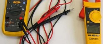
As is known, in the AC network of a home network, the potential difference changes with a frequency of 50 Hz. That is, 50 complete oscillations are produced every second. This phenomenon is easy to measure even with a household frequency meter, which determines the exact value of this parameter precisely by the effect of the electromagnetic field formed around the current-carrying conductor. A coil with a metal core, which is installed in a measuring device, will oscillate with the frequency of the electromagnetic field of the home electrical system.
You may be interested in this Determination of short circuit current
Frequency meter
Thus, an alternating voltage is generated, which can then be increased, and its frequency is calculated by a microprocessor or analog device, after which the information can be displayed on the screen.
Having understood what the phenomenon of electrical voltage resonance is, it is necessary to try in every possible way to avoid this phenomenon when simultaneous oscillatory movements of fields are undesirable. If in any device such an effect is used to obtain certain physical phenomena, then the circuit must be manufactured with a high quality factor so that as little energy as possible is spent on maintaining the process (thus increasing the efficiency of the device).